Page 1298 of 1833
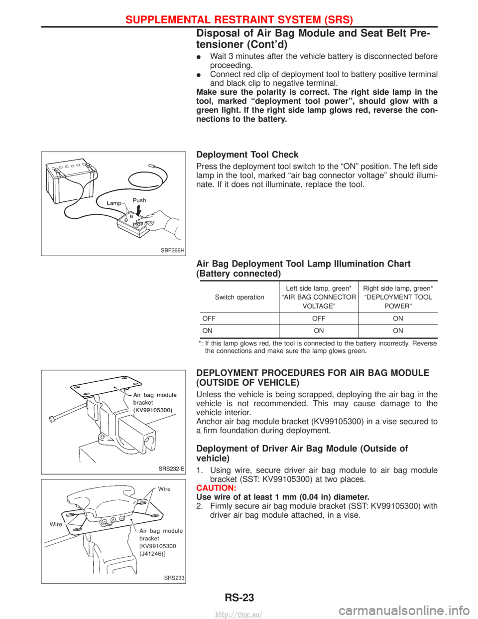
IWait 3 minutes after the vehicle battery is disconnected before
proceeding.
I Connect red clip of deployment tool to battery positive terminal
and black clip to negative terminal.
Make sure the polarity is correct. The right side lamp in the
tool, marked ªdeployment tool powerº, should glow with a
green light. If the right side lamp glows red, reverse the con-
nections to the battery.
Deployment Tool Check
Press the deployment tool switch to the ªONº position. The left side
lamp in the tool, marked ªair bag connector voltageº should illumi-
nate. If it does not illuminate, replace the tool.
Air Bag Deployment Tool Lamp Illumination Chart
(Battery connected)
Switch operation Left side lamp, green*
ªAIR BAG CONNECTOR VOLTAGEº Right side lamp, green*
ªDEPLOYMENT TOOL POWERº
OFF OFFON
ON ON ON
*: If this lamp glows red, the tool is connected to the battery incorrectly. Reverse the connections and make sure the lamp glows green.
DEPLOYMENT PROCEDURES FOR AIR BAG MODULE
(OUTSIDE OF VEHICLE)
Unless the vehicle is being scrapped, deploying the air bag in the
vehicle is not recommended. This may cause damage to the
vehicle interior.
Anchor air bag module bracket (KV99105300) in a vise secured to
a firm foundation during deployment.
Deployment of Driver Air Bag Module (Outside of
vehicle)
1. Using wire, secure driver air bag module to air bag module bracket (SST: KV99105300) at two places.
CAUTION:
Use wire of at least 1 mm (0.04 in) diameter.
2. Firmly secure air bag module bracket (SST: KV99105300) with driver air bag module attached, in a vise.
SBF266H
SRS232-E
SRS233
SUPPLEMENTAL RESTRAINT SYSTEM (SRS)
Disposal of Air Bag Module and Seat Belt Pre-
tensioner (Cont'd)
RS-23
http://vnx.su/
Page 1304 of 1833
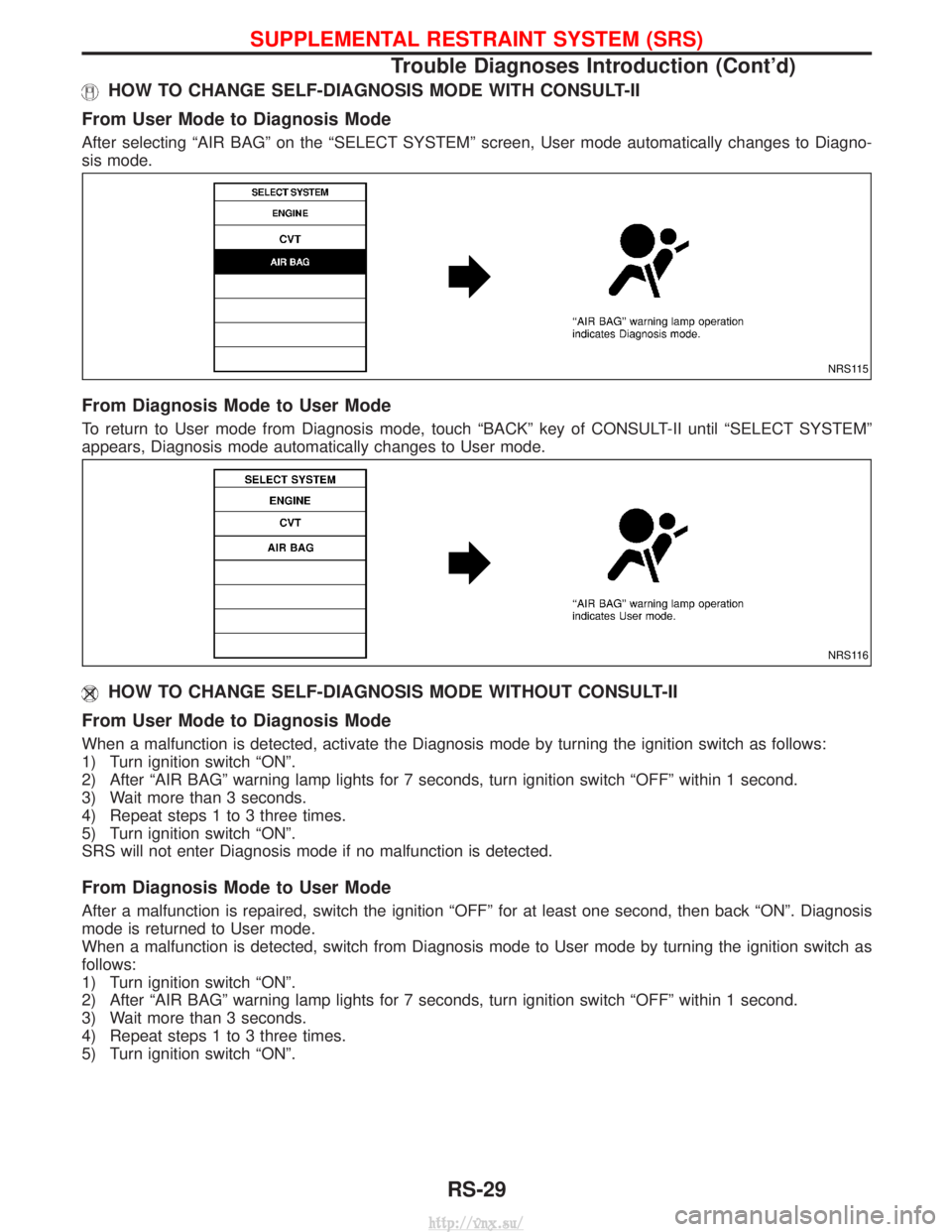
HOW TO CHANGE SELF-DIAGNOSIS MODE WITH CONSULT-II
From User Mode to Diagnosis Mode
After selecting ªAIR BAGº on the ªSELECT SYSTEMº screen, User mode automatically changes to Diagno-
sis mode.
From Diagnosis Mode to User Mode
To return to User mode from Diagnosis mode, touch ªBACKº key of CONSULT-II until ªSELECT SYSTEMº
appears, Diagnosis mode automatically changes to User mode.
HOW TO CHANGE SELF-DIAGNOSIS MODE WITHOUT CONSULT-II
From User Mode to Diagnosis Mode
When a malfunction is detected, activate the Diagnosis mode by turning the ignition switch as follows:
1) Turn ignition switch ªONº.
2) After ªAIR BAGº warning lamp lights for 7 seconds, turn ignition switch ªOFFº within 1 second.
3) Wait more than 3 seconds.
4) Repeat steps 1 to 3 three times.
5) Turn ignition switch ªONº.
SRS will not enter Diagnosis mode if no malfunction is detected.
From Diagnosis Mode to User Mode
After a malfunction is repaired, switch the ignition ªOFFº for at least one second, then back ªONº. Diagnosis
mode is returned to User mode.
When a malfunction is detected, switch from Diagnosis mode to User mode by turning the ignition switch as
follows:
1) Turn ignition switch ªONº.
2) After ªAIR BAGº warning lamp lights for 7 seconds, turn ignition switch ªOFFº within 1 second.
3) Wait more than 3 seconds.
4) Repeat steps 1 to 3 three times.
5) Turn ignition switch ªONº.
NRS115
NRS116
SUPPLEMENTAL RESTRAINT SYSTEM (SRS)
Trouble Diagnoses Introduction (Cont'd)
RS-29
http://vnx.su/
Page 1323 of 1833
![NISSAN TERRANO 2004 Service Repair Manual Diagnostic itemExplanationRepair order
PRE-TEN FRONT RH
[OPEN/VB-SHORT] I
The circuit for front RH seat belt pre-
tensioner is open or shorted to a power
supply circuit. 1. Visually check the wiring h NISSAN TERRANO 2004 Service Repair Manual Diagnostic itemExplanationRepair order
PRE-TEN FRONT RH
[OPEN/VB-SHORT] I
The circuit for front RH seat belt pre-
tensioner is open or shorted to a power
supply circuit. 1. Visually check the wiring h](/manual-img/5/57394/w960_57394-1322.png)
Diagnostic itemExplanationRepair order
PRE-TEN FRONT RH
[OPEN/VB-SHORT] I
The circuit for front RH seat belt pre-
tensioner is open or shorted to a power
supply circuit. 1. Visually check the wiring harness con-
nections.
2. Replace the harness if it has visible damage.
3. If the harness check is OK, replace the diagnosis sensor unit and front RH seat
belt. (Before disposing of the front RH
seat belt pre-tensioner, if must be
deployed.)
PRE-TEN FRONT RH
[GND-SHORT]
I
The circuit for front RH seat belt pre-
tensioner is shorted to ground.
CONTROL UNIT IDiagnosis sensor unit is malfunctioning. 1. Visually check the wiring harness con-
nection.
2. Replace the harness if it has visible damage.
3. If the harness check is OK, replace the diagnosis sensor unit.
* Follow the procedures in numerical order when repairing malfunctioning parts, then make the final system check.
Trouble Diagnoses without CONSULT-II
DIAGNOSTIC PROCEDURE 6
Inspecting SRS malfunctioning parts by using ªAIR BAGº
warning lamp Ð Diagnosis mode
NOTE:
SRS will not enter Diagnosis mode if no malfunction is
detected in User mode.
1. Turn ignition switch ªONº.
2. After ªAIR BAGº warning lamp lights for 7 seconds, turn ignition switch ªOFFº within 1 second.
3. Wait more than 3 seconds.
4. Repeat steps 1 to 3 three times.
5. Turn ignition switch ªONº. SRS is now in Diagnosis mode.
6. ªAIR BAGº warning lamp operates in Diagnosis mode as fol- lows:
NOTE:
If SRS does not enter Diagnosis mode even though malfunc-
tion is detected in User mode, check the battery voltage.
If the battery voltage is less than 9V, charge the battery. Then
go to DIAGNOSTIC PROCEDURE 7, page RS-53.
If the battery voltage is OK, replace the diagnosis sensor unit.
SRS800
SUPPLEMENTAL RESTRAINT SYSTEM (SRS)
Trouble Diagnoses with CONSULT-II (Cont'd)
RS-48
http://vnx.su/
Page 1330 of 1833
1) Turn ignition switch ªONº.
2) After ªAIR BAGº warning lamp lights for 7 seconds, turn ignitionswitch ªOFFº within 1 second.
3) Wait more than 3 seconds.
4) Repeat steps 1 to 3 three times.
5) Turn ignition switch ªONº.
SRS is now in User mode.
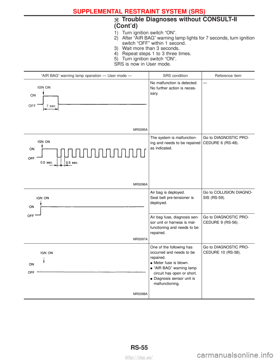
ªAIR BAGº warning lamp operation Ð User mode Ð SRS conditionReference item
MRS095A
No malfunction is detected.
No further action is neces-
sary. Ð
MRS096A
The system is malfunction-
ing and needs to be repaired
as indicated.Go to DIAGNOSTIC PRO-
CEDURE 6 (RS-48).
MRS097A
Air bag is deployed.
Seat belt pre-tensioner is
deployed.Go to COLLISION DIAGNO-
SIS (RS-59).
Air bag fuse, diagnosis sen-
sor unit or harness is mal-
functioning and needs to be
repaired. Go to DIAGNOSTIC PRO-
CEDURE 9 (RS-56).
MRS098A
One of the following has
occurred and needs to be
repaired.
I
Meter fuse is blown.
I ªAIR BAGº warning lamp
circuit has open or short.
I Diagnosis sensor unit is
malfunctioning. Go to DIAGNOSTIC PRO-
CEDURE 10 (RS-58).
SUPPLEMENTAL RESTRAINT SYSTEM (SRS)
Trouble Diagnoses without CONSULT-II
(Cont'd)
RS-55
http://vnx.su/
Page 1404 of 1833
Control Operation
FAN CONTROL DIAL
This DIAL turns the fan ON and OFF, and controls fan speed.
AIR CONTROL DIAL
This DIAL allows outlet air to flow.
TEMPERATURE CONTROL DIAL
This DIAL allows the temperature of the outlet air to be adjusted.
AIR RECIRCULATION SWITCH
OFF position:
Outside air is drawn into the passenger compartment.
ON position (Indicator light ON):
Interior air is recirculated inside the vehicle.
AIR CONDITIONER SWITCH
Start the engine, turn the fan control dial to the desired (1 to 4) position and press the air conditioner switch
to turn ON the air conditioner. The indicator light will come on when the air conditioner is ON. To stop the air
conditioner, push the switch again to return it to the original position.
The air conditioner cooling function operates only when the engine is running.
NHA331
DESCRIPTION Ð Overall System
HA-7
http://vnx.su/
Page 1409 of 1833
HFC-134a (R-134a) Service Tools and
Equipment
It is important to understand that HFC-134a (R-134a) refrigerant, and the specified lubricant which must be
used with HFC-134a (R-134a), must never be mixed with CFC-12 (R-12) refrigerant and/or the CFC-12 (R-12)
lubricant.
This means that separate and non-interchangeable service equipment must be used for handling each type
of refrigerant/lubricant.
To prevent the mixing of refrigerants/lubricants, refrigerant container fittings, service hose fittings, and service
equipment fittings (equipment which handles refrigerant and/or lubricant) are different between CFC-12 (R-12)
and HFC-134a (R-134a).
Adaptors to convert from one size of fitting to another must never be used: refrigerant/lubricant contamination
will occur and compressor failure will result.
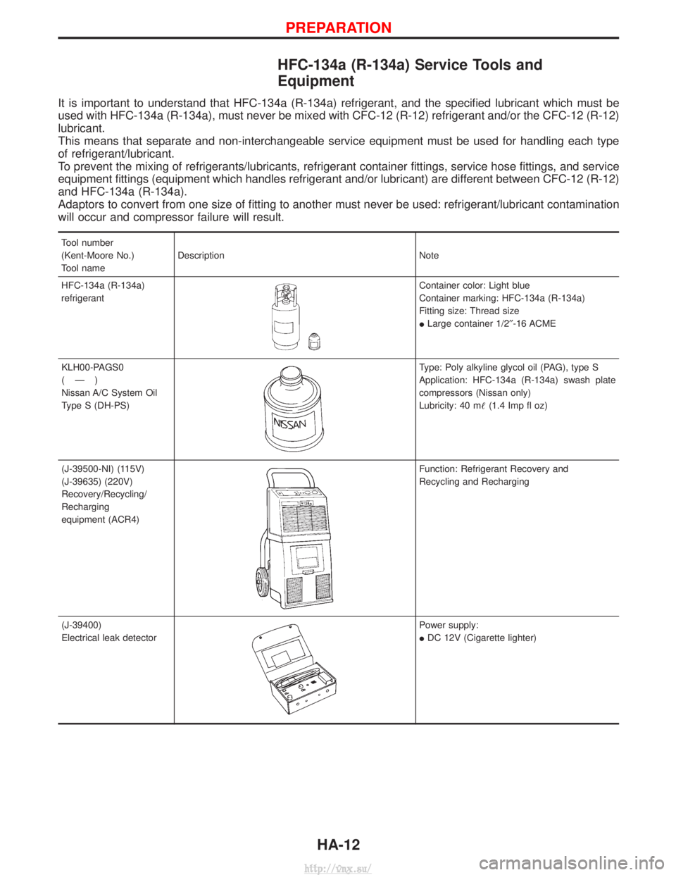
Tool number
(Kent-Moore No.)
Tool nameDescription Note
HFC-134a (R-134a)
refrigerant
Container color: Light blue
Container marking: HFC-134a (R-134a)
Fitting size: Thread size
I Large container 1/2² -16 ACME
KLH00-PAGS0
(Ð)
Nissan A/C System Oil
Type S (DH-PS)
Type: Poly alkyline glycol oil (PAG), type S
Application: HFC-134a (R-134a) swash plate
compressors (Nissan only)
Lubricity: 40 m (1.4 Imp fl oz)
(J-39500-NI) (115V)
(J-39635) (220V)
Recovery/Recycling/
Recharging
equipment (ACR4)
Function: Refrigerant Recovery and
Recycling and Recharging
(J-39400)
Electrical leak detector
Power supply:
I DC 12V (Cigarette lighter)
PREPARATION
HA-12
http://vnx.su/
Page 1426 of 1833
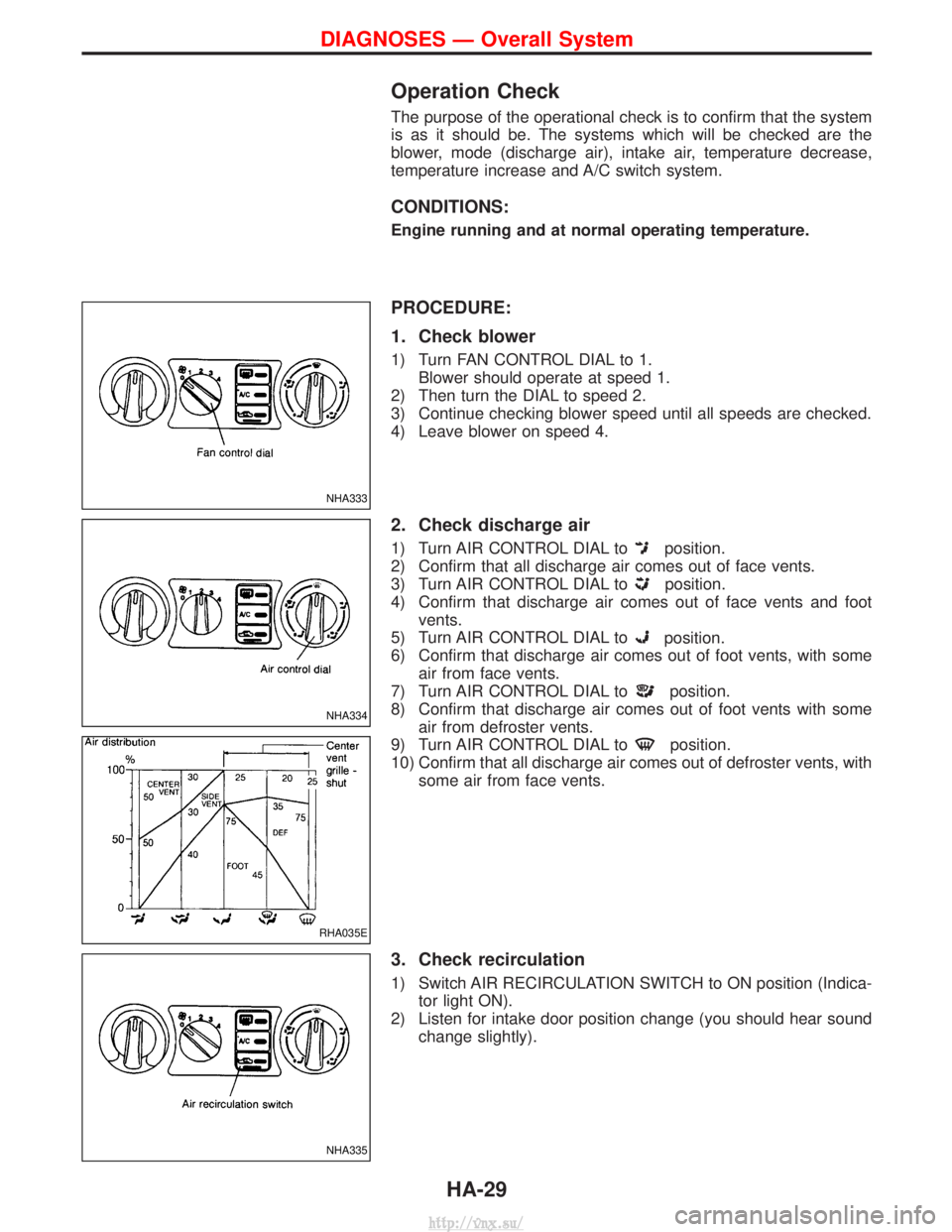
Operation Check
The purpose of the operational check is to confirm that the system
is as it should be. The systems which will be checked are the
blower, mode (discharge air), intake air, temperature decrease,
temperature increase and A/C switch system.
CONDITIONS:
Engine running and at normal operating temperature.
PROCEDURE:
1. Check blower
1) Turn FAN CONTROL DIAL to 1.Blower should operate at speed 1.
2) Then turn the DIAL to speed 2.
3) Continue checking blower speed until all speeds are checked.
4) Leave blower on speed 4.
2. Check discharge air
1) Turn AIR CONTROL DIAL toposition.
2) Confirm that all discharge air comes out of face vents.
3) Turn AIR CONTROL DIAL to
position.
4) Confirm that discharge air comes out of face vents and foot vents.
5) Turn AIR CONTROL DIAL to
position.
6) Confirm that discharge air comes out of foot vents, with some air from face vents.
7) Turn AIR CONTROL DIAL to
position.
8) Confirm that discharge air comes out of foot vents with some air from defroster vents.
9) Turn AIR CONTROL DIAL to
position.
10) Confirm that all discharge air comes out of defroster vents, with some air from face vents.
3. Check recirculation
1) Switch AIR RECIRCULATION SWITCH to ON position (Indica-tor light ON).
2) Listen for intake door position change (you should hear sound change slightly).
NHA333
NHA334
RHA035E
NHA335
DIAGNOSES Ð Overall System
HA-29
http://vnx.su/
Page 1427 of 1833
4. Check temperature decrease
1) Turn TEMPERATURE CONTROL DIAL to full cold (counter-clockwise).
2) Check for cold air at discharge air outlets.
5. Check temperature increase
1) Turn TEMPERATURE CONTROL DIAL to full hot (clockwise).
2) Check for hot air at discharge air outlets.
6. Check A/C switch
Turn FAN CONTROL DIAL to the desired position (1 to 4) and
switch AIR CONDITIONER SWITCH to turn ON air conditioner.
Indicator light will come on when air conditioner is ON.
NHA336
NHA337
NHA338
DIAGNOSES Ð Overall System
Operation Check (Cont'd)
HA-30
http://vnx.su/