2004 NISSAN TERRANO Rocker
[x] Cancel search: RockerPage 92 of 1833
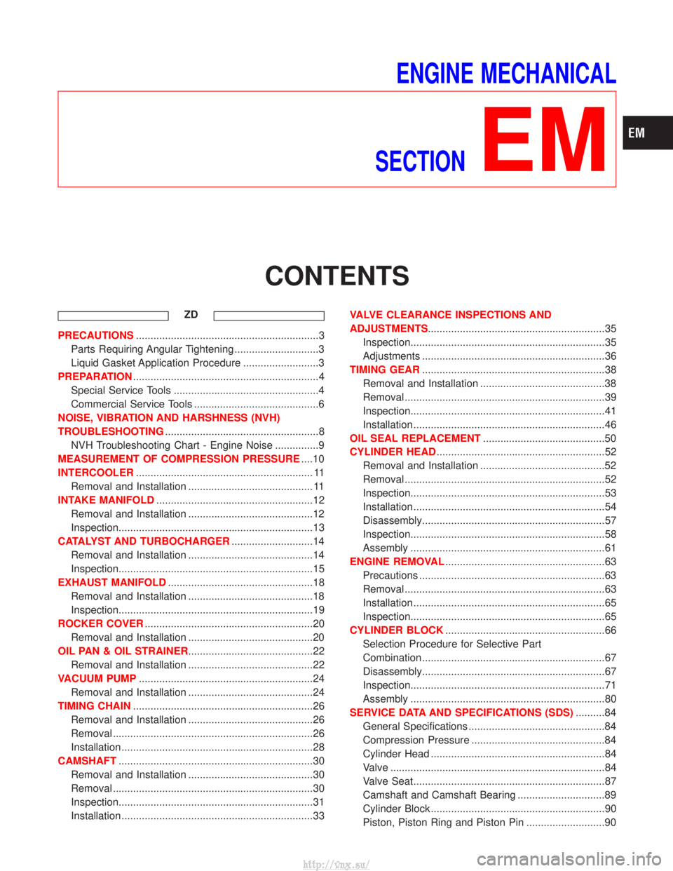
ENGINE MECHANICAL
SECTION
EM
CONTENTS
ZD
PRECAUTIONS ...............................................................3
Parts Requiring Angular Tightening .............................3
Liquid Gasket Application Procedure ..........................3
PREPARATION ................................................................4
Special Service Tools ..................................................4
Commercial Service Tools ...........................................6
NOISE, VIBRATION AND HARSHNESS (NVH)
TROUBLESHOOTING .....................................................8
NVH Troubleshooting Chart - Engine Noise ...............9
MEASUREMENT OF COMPRESSION PRESSURE ....10
INTERCOOLER ............................................................. 11
Removal and Installation ........................................... 11
INTAKE MANIFOLD ......................................................12
Removal and Installation ...........................................12
Inspection...................................................................13
CATALYST AND TURBOCHARGER ............................14
Removal and Installation ...........................................14
Inspection...................................................................15
EXHAUST MANIFOLD ..................................................18
Removal and Installation ...........................................18
Inspection...................................................................19
ROCKER COVER ..........................................................20
Removal and Installation ...........................................20
OIL PAN & OIL STRAINER ...........................................22
Removal and Installation ...........................................22
VACUUM PUMP ............................................................24
Removal and Installation ...........................................24
TIMING CHAIN ..............................................................26
Removal and Installation ...........................................26
Removal .....................................................................26
Installation ..................................................................28
CAMSHAFT ...................................................................30
Removal and Installation ...........................................30
Removal .....................................................................30
Inspection...................................................................31
Installation ..................................................................33 VALVE CLEARANCE INSPECTIONS AND
ADJUSTMENTS
.............................................................35
Inspection...................................................................35
Adjustments ...............................................................36
TIMING GEAR ...............................................................38
Removal and Installation ...........................................38
Removal .....................................................................39
Inspection...................................................................41
Installation ..................................................................46
OIL SEAL REPLACEMENT ..........................................50
CYLINDER HEAD ..........................................................52
Removal and Installation ...........................................52
Removal .....................................................................52
Inspection...................................................................53
Installation ..................................................................54
Disassembly...............................................................57
Inspection...................................................................58
Assembly ...................................................................61
ENGINE REMOVAL .......................................................63
Precautions ................................................................63
Removal .....................................................................63
Installation ..................................................................65
Inspection...................................................................65
CYLINDER BLOCK .......................................................66
Selection Procedure for Selective Part
Combination ...............................................................67
Disassembly...............................................................67
Inspection...................................................................71
Assembly ...................................................................80
SERVICE DATA AND SPECIFICATIONS (SDS) ..........84
General Specifications ...............................................84
Compression Pressure ..............................................84
Cylinder Head ............................................................84
Valve ........................................................................\
..84
Valve Seat..................................................................87
Camshaft and Camshaft Bearing ..............................89
Cylinder Block ............................................................90
Piston, Piston Ring and Piston Pin ...........................90
http://vnx.su/
Page 100 of 1833
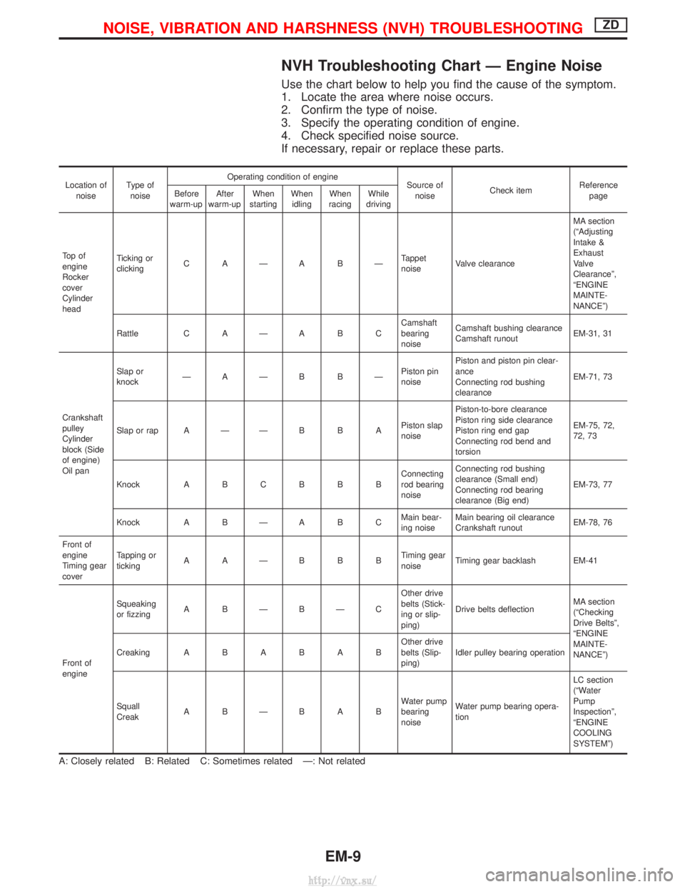
NVH Troubleshooting Chart Ð Engine Noise
Use the chart below to help you find the cause of the symptom.
1. Locate the area where noise occurs.
2. Confirm the type of noise.
3. Specify the operating condition of engine.
4. Check specified noise source.
If necessary, repair or replace these parts.
Location ofnoise Type of
noise Operating condition of engine
Source of
noise Check item Reference
page
Before
warm-up After
warm-up When
starting When
idling When
racing While
driving
To p o f
engine
Rocker
cover
Cylinder
head Ticking or
clicking
C AÐA BÐ Tappet
noiseValve clearance MA section
(ªAdjusting
Intake &
Exhaust
Valve
Clearanceº,
ªENGINE
MAINTE-
NANCEº)
Rattle C A Ð A B C Camshaft
bearing
noiseCamshaft bushing clearance
Camshaft runout
EM-31, 31
Crankshaft
pulley
Cylinder
block (Side
of engine)
Oil pan Slap or
knock
ÐAÐB BÐ Piston pin
noisePiston and piston pin clear-
ance
Connecting rod bushing
clearance
EM-71, 73
Slap or rap A Ð Ð B B A Piston slap
noisePiston-to-bore clearance
Piston ring side clearance
Piston ring end gap
Connecting rod bend and
torsion EM-75, 72,
72, 73
Knock A B C B B B Connecting
rod bearing
noiseConnecting rod bushing
clearance (Small end)
Connecting rod bearing
clearance (Big end)
EM-73, 77
Knock A B Ð A B C Main bear-
ing noiseMain bearing oil clearance
Crankshaft runout
EM-78, 76
Front of
engine
Timing gear
cover Tapping or
ticking
AAÐBBB Timing gear
noiseTiming gear backlash EM-41
Front of
engine Squeaking
or fizzing
A BÐBÐC Other drive
belts (Stick-
ing or slip-
ping)Drive belts deflection
MA section
(ªChecking
Drive Beltsº,
ªENGINE
MAINTE-
NANCEº)
Creaking
ABABAB Other drive
belts (Slip-
ping)Idler pulley bearing operation
Squall
Creak ABÐBAB Water pump
bearing
noiseWater pump bearing opera-
tion LC section
(ªWater
Pump
Inspectionº,
ªENGINE
COOLING
SYSTEMº)
A: Closely related B: Related C: Sometimes related Ð: Not related
NOISE, VIBRATION AND HARSHNESS (NVH) TROUBLESHOOTINGZD
EM-9
http://vnx.su/
Page 101 of 1833
1. Warm up engine.
2. Turn ignition switch OFF.
3. Using CONSULT-II, make sure no error codes are indicated forself-diagnosis items. Refer to EC section, ªFuel Pressure
Releaseº.
I Do not disconnect CONSULT-II until the end of this operation;
it will be used to check engine rpm and for error detection at
the end of this operation.
4. Disconnect the negative battery terminal.
5. Remove the following parts.
I Intercooler
I Throttle body
I Rocker cover
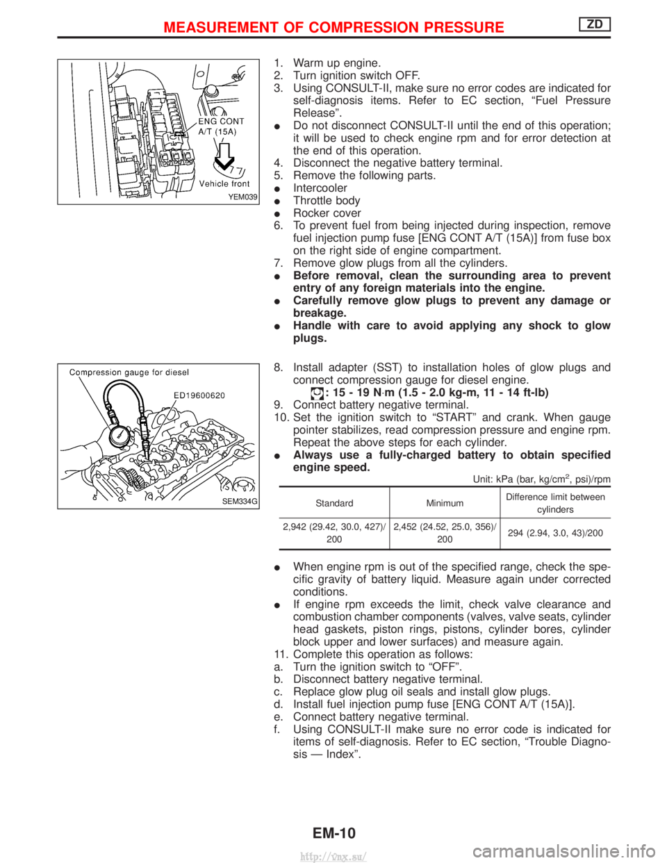
6. To prevent fuel from being injected during inspection, remove fuel injection pump fuse [ENG CONT A/T (15A)] from fuse box
on the right side of engine compartment.
7. Remove glow plugs from all the cylinders.
I Before removal, clean the surrounding area to prevent
entry of any foreign materials into the engine.
I Carefully remove glow plugs to prevent any damage or
breakage.
I Handle with care to avoid applying any shock to glow
plugs.
8. Install adapter (SST) to installation holes of glow plugs and connect compression gauge for diesel engine.
:15-19N ×m (1.5 - 2.0 kg-m, 11 - 14 ft-lb)
9. Connect battery negative terminal.
10. Set the ignition switch to ªSTARTº and crank. When gauge pointer stabilizes, read compression pressure and engine rpm.
Repeat the above steps for each cylinder.
I Always use a fully-charged battery to obtain specified
engine speed.
Unit: kPa (bar, kg/cm2, psi)/rpm
Standard MinimumDifference limit between
cylinders
2,942 (29.42, 30.0, 427)/ 200 2,452 (24.52, 25.0, 356)/
200 294 (2.94, 3.0, 43)/200
I
When engine rpm is out of the specified range, check the spe-
cific gravity of battery liquid. Measure again under corrected
conditions.
I If engine rpm exceeds the limit, check valve clearance and
combustion chamber components (valves, valve seats, cylinder
head gaskets, piston rings, pistons, cylinder bores, cylinder
block upper and lower surfaces) and measure again.
11. Complete this operation as follows:
a. Turn the ignition switch to ªOFFº.
b. Disconnect battery negative terminal.
c. Replace glow plug oil seals and install glow plugs.
d. Install fuel injection pump fuse [ENG CONT A/T (15A)].
e. Connect battery negative terminal.
f. Using CONSULT-II make sure no error code is indicated for items of self-diagnosis. Refer to EC section, ªTrouble Diagno-
sis Ð Indexº.
YEM039
SEM334G
MEASUREMENT OF COMPRESSION PRESSUREZD
EM-10
http://vnx.su/
Page 111 of 1833
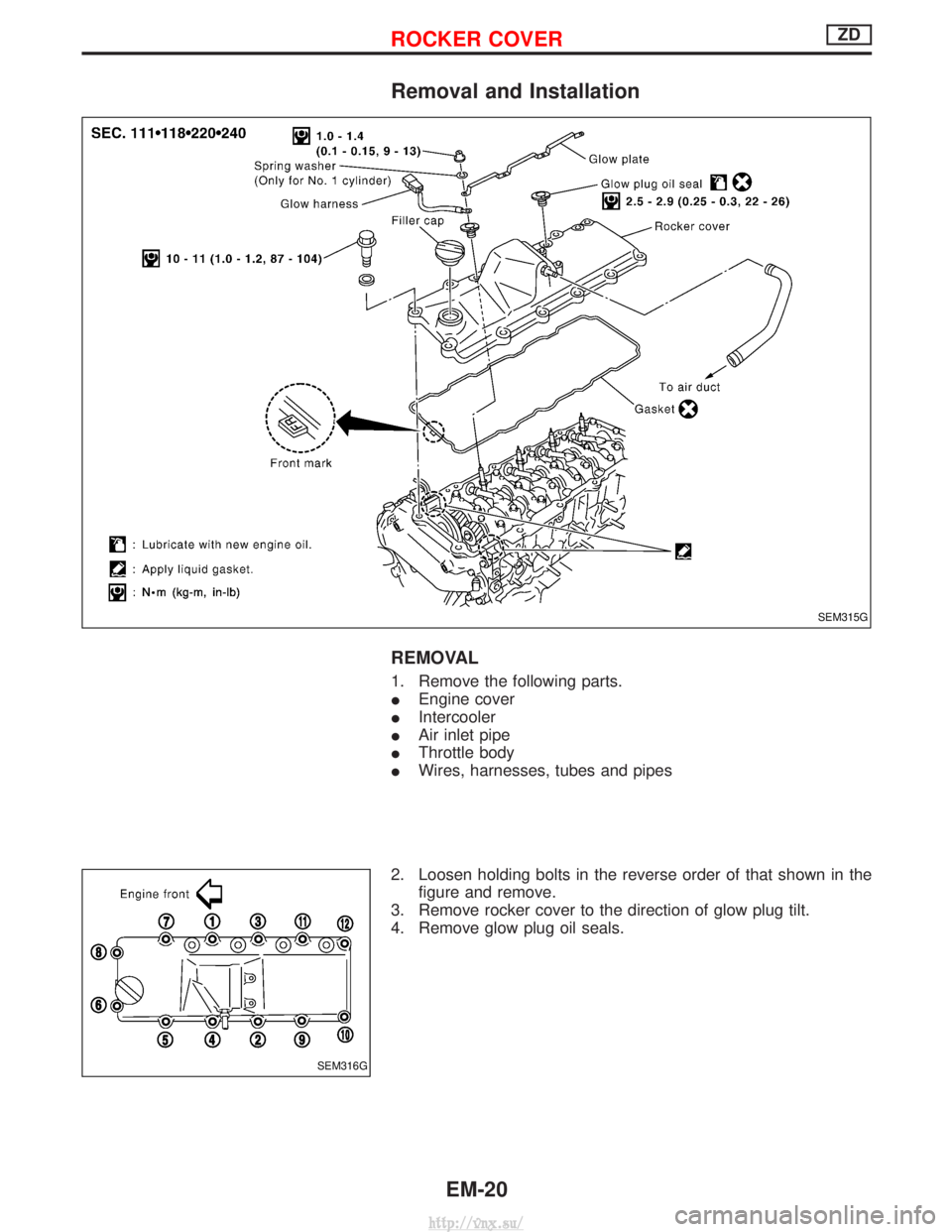
Removal and Installation
REMOVAL
1. Remove the following parts.
IEngine cover
I Intercooler
I Air inlet pipe
I Throttle body
I Wires, harnesses, tubes and pipes
2. Loosen holding bolts in the reverse order of that shown in the figure and remove.
3. Remove rocker cover to the direction of glow plug tilt.
4. Remove glow plug oil seals.
SEM315G
SEM316G
ROCKER COVERZD
EM-20
http://vnx.su/
Page 112 of 1833
INSTALLATION
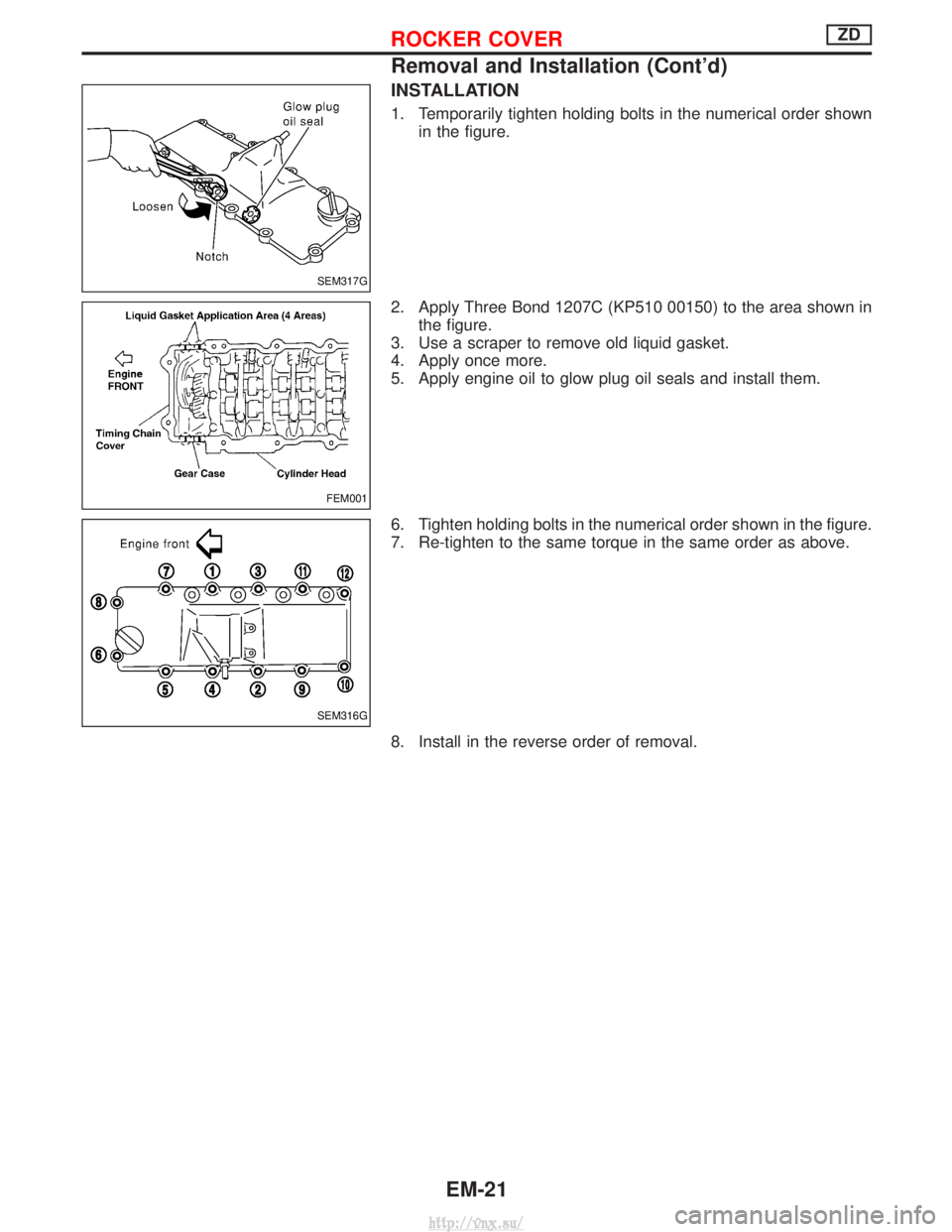
1. Temporarily tighten holding bolts in the numerical order shownin the figure.
2. Apply Three Bond 1207C (KP510 00150) to the area shown in the figure.
3. Use a scraper to remove old liquid gasket.
4. Apply once more.
5. Apply engine oil to glow plug oil seals and install them.
6. Tighten holding bolts in the numerical order shown in the figure.
7. Re-tighten to the same torque in the same order as above.
8. Install in the reverse order of removal.
SEM317G
FEM001
SEM316G
ROCKER COVERZD
Removal and Installation (Cont'd)
EM-21
http://vnx.su/
Page 117 of 1833
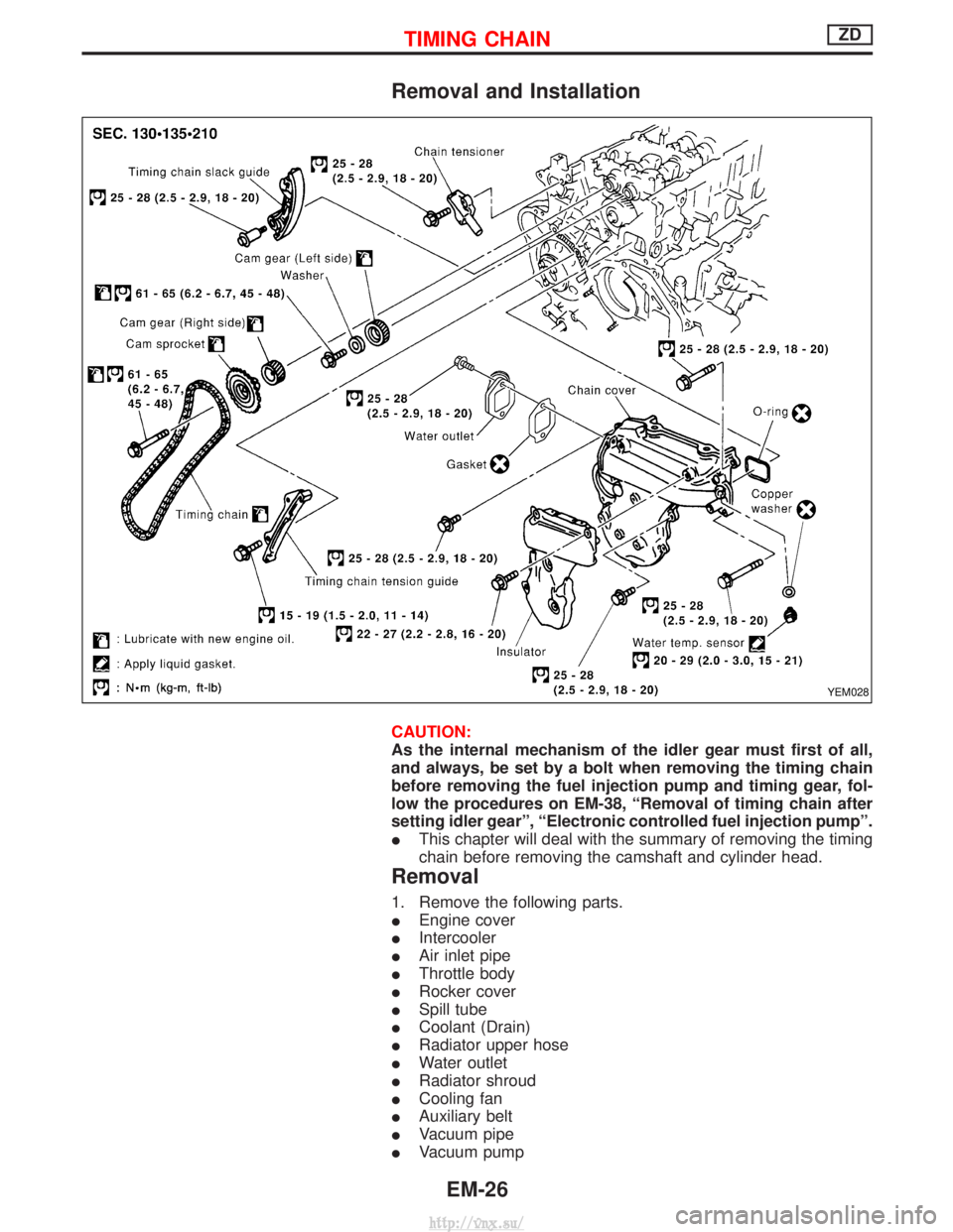
Removal and Installation
CAUTION:
As the internal mechanism of the idler gear must first of all,
and always, be set by a bolt when removing the timing chain
before removing the fuel injection pump and timing gear, fol-
low the procedures on EM-38, ªRemoval of timing chain after
setting idler gearº, ªElectronic controlled fuel injection pumpº.
IThis chapter will deal with the summary of removing the timing
chain before removing the camshaft and cylinder head.
Removal
1. Remove the following parts.
IEngine cover
I Intercooler
I Air inlet pipe
I Throttle body
I Rocker cover
I Spill tube
I Coolant (Drain)
I Radiator upper hose
I Water outlet
I Radiator shroud
I Cooling fan
I Auxiliary belt
I Vacuum pipe
I Vacuum pump
YEM028
TIMING CHAINZD
EM-26
http://vnx.su/
Page 126 of 1833
Inspection
IWhen the camshaft or parts in connection with valves are
removed or replaced, and a fault has occurred (poor starting,
idling, or other faults) due to the misadjustment of the valve
clearance, inspect as follows.
I Inspect and adjust when the engine is cool (at normal tempera-
ture).
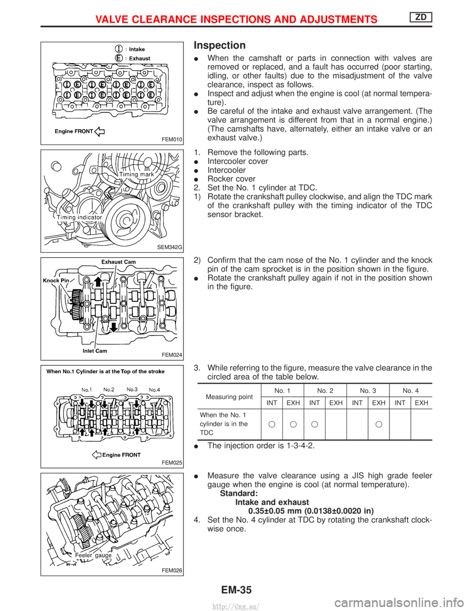
I Be careful of the intake and exhaust valve arrangement. (The
valve arrangement is different from that in a normal engine.)
(The camshafts have, alternately, either an intake valve or an
exhaust valve.)
1. Remove the following parts.
I Intercooler cover
I Intercooler
I Rocker cover
2. Set the No. 1 cylinder at TDC.
1) Rotate the crankshaft pulley clockwise, and align the TDC mark of the crankshaft pulley with the timing indicator of the TDC
sensor bracket.
2) Confirm that the cam nose of the No. 1 cylinder and the knock pin of the cam sprocket is in the position shown in the figure.
I Rotate the crankshaft pulley again if not in the position shown
in the figure.
3. While referring to the figure, measure the valve clearance in the circled area of the table below.
Measuring point No. 1 No. 2 No. 3 No. 4
INT EXH INT EXH INT EXH INT EXH
When the No. 1
cylinder is in the
TDC qqq q
I
The injection order is 1-3-4-2.
I Measure the valve clearance using a JIS high grade feeler
gauge when the engine is cool (at normal temperature).
Standard: Intake and exhaust0.35 0.05 mm (0.0138 0.0020 in)
4. Set the No. 4 cylinder at TDC by rotating the crankshaft clock- wise once.
FEM010
SEM342G
FEM024
FEM025
FEM026
VALVE CLEARANCE INSPECTIONS AND ADJUSTMENTSZD
EM-35
http://vnx.su/
Page 130 of 1833
Removal
1. Remove the engine assembly.Refer to ªENGINE REMOVALº, EM-63.
2. Place the engine on an engine stand (SST). Refer to ªCYLINDER BLOCKº, EM-67.
3. Remove the following.
I Auto tensioner bracket
I Air conditioner bracket
I Alternator bracket
I Oil tube
I Vacuum pump
I Rocker cover
I Oil pan (upper, lower)
I Injection tube
I Spill tube
I High pressure nozzle assembly
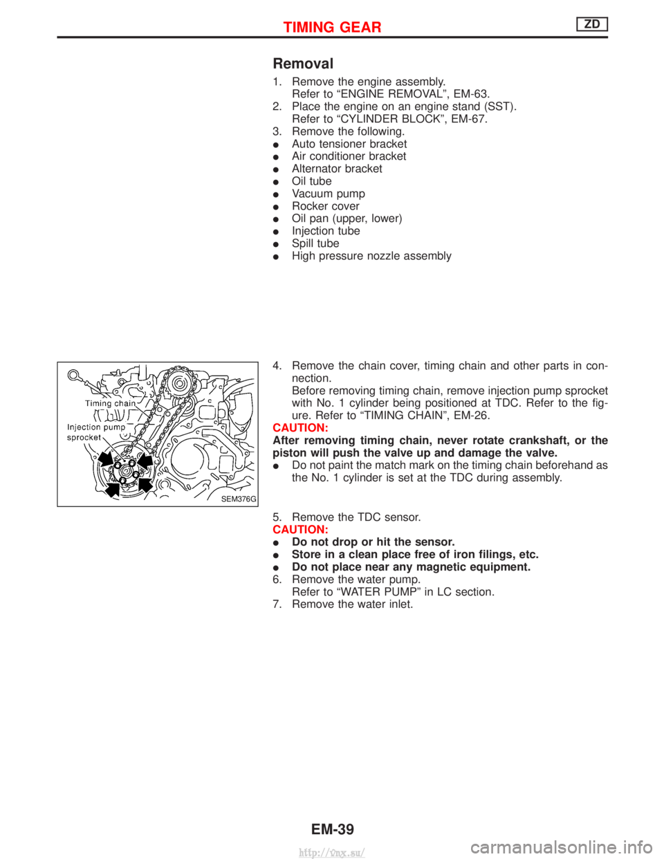
4. Remove the chain cover, timing chain and other parts in con- nection.
Before removing timing chain, remove injection pump sprocket
with No. 1 cylinder being positioned at TDC. Refer to the fig-
ure. Refer to ªTIMING CHAINº, EM-26.
CAUTION:
After removing timing chain, never rotate crankshaft, or the
piston will push the valve up and damage the valve.
I Do not paint the match mark on the timing chain beforehand as
the No. 1 cylinder is set at the TDC during assembly.
5. Remove the TDC sensor.
CAUTION:
I Do not drop or hit the sensor.
I Store in a clean place free of iron filings, etc.
I Do not place near any magnetic equipment.
6. Remove the water pump. Refer to ªWATER PUMPº in LC section.
7. Remove the water inlet.
SEM376G
TIMING GEARZD
EM-39
http://vnx.su/