Page 204 of 1833
Assembly
1. Assemble rocker shaft component parts.
IIdentification of rocker arms
Identification mark
(on rocker arm) For use with
B Intake valve
C Exhaust valve
2. Install valve component parts.
I Always use new valve oil seal. Refer to ªVALVE STEM OIL
SEALº.
I Intake and exhaust valve springs are interchangeable.
3. Assemble all removed parts in reverse order of disassembly.
SEM637B
EEM093
CYLINDER HEADTD27Ti
EM-113
http://vnx.su/
Page 206 of 1833
2. Install cylinder head.
ICylinder head identification mark
3. Apply oil to threaded portion and seat surface of bolts and tighten cylinder head bolts using Tool.
CAUTION:
I Tightening procedure
1st: Tighten bolts to 39 - 44 N×m (4.0 - 4.5 kg-m, 29 - 33 ft-lb)
2nd: Tighten bolts to 54 - 59 N ×m
(5.5 - 6.0 kg-m, 40 - 43 ft-lb)
3rd: (1) Mark exhaust side of cylinder head and cylin-der head bolts with paint as shown.
(2) Turn all bolts 90 10 degrees clockwise.
(3) Check that paint mark of each bolt is facing the front of the vehicle.
4. Apply engine oil and install push rods.
5. Install rocker shaft assembly. Adjust intake and exhaust valve clearance carefully.
Refer to MA section in order to accomplish valve adjustment.
NEM179
SEM641B
SEM580C
SEM642B
CYLINDER HEADTD27Ti
Installation (Cont'd)
EM-115
http://vnx.su/
Page 207 of 1833
6. Install rocker cover.
IBe sure to tighten bolts in the order shown in the illustration.
I When replacing rocker cover gasket, bend slit of rocker cover
baffle plate a little to hold the gasket. Do not twist gasket.
7. Install glow plugs and glow plate.
8. Install new top nozzle gasket and injection nozzle.
9. Install thermostat housing bolts shown at left.
10. Install spill tube and injection tube. Spill tube nut:
:39-49N ×m (4.0 - 5.0 kg-m, 29 - 36 ft-lb)
Injection tubes:
:20-25N ×m (2.0 - 2.5 kg-m, 14 - 18 ft-lb)
11. Connect thermostat housing water inlet hose and radiator hose.
12. Install all removed parts in reverse order of removal.
13. After assembling all disassembled parts, fill radiator and engine with new coolant up to filler opening.
Refer to MA section.
NEM163
SEM618B
EEM103
SEM621B
CYLINDER HEADTD27Ti
Installation (Cont'd)
EM-116
http://vnx.su/
Page 208 of 1833
VALVE STEM OIL SEAL
1. Remove rocker cover.
2. Remove rocker shaft assembly.
3. Remove valve spring.
Piston concerned should be set at TDC to prevent valve from
falling.
4. Remove valve oil seals.
5. Apply engine oil to valve oil seal and install it in place.
SEM645B
SEM626B
SEM646B
SEM223B
OIL SEAL REPLACEMENTTD27Ti
EM-117
http://vnx.su/
Page 238 of 1833

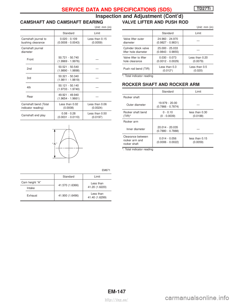
CAMSHAFT AND CAMSHAFT BEARING
Unit: mm (in)
StandardLimit
Camshaft journal to
bushing clearance 0.020 - 0.109
(0.0008 - 0.0043) Less than 0.15
(0.0059)
Camshaft journal
diameter
Front 50.721 - 50.740
(1.9969 - 1.9976) Ð
2nd 50.521 - 50.540
(1.9890 - 1.9898) Ð
3rd 50.321 - 50.340
(1.9811 - 1.9819) Ð
4th 50.121 - 50.140
(1.9733 - 1.9740) Ð
Rear 49.921 - 49.940
(1.9654 - 1.9661) Ð
Camshaft bend (Total
indicator reading) Less than 0.02
(0.0008) Less than 0.06
(0.0024)
Camshaft end play 0.08 - 0.28
(0.0031 - 0.0110) Less than 0.50
(0.0197)
EM671
Standard Limit
Cam height ªAº 41.570 (1.6366)Less than
41.20 (1.6220)
Intake
Exhaust 41.900 (1.6496) Less than
41.40 (1.6299)
VALVE LIFTER AND PUSH ROD
Unit: mm (in)
Standard Limit
Valve lifter outer
diameter 24.960 - 24.970
(0.9827 - 0.9831) Ð
Cylinder block valve
lifter hole diameter 25.000 - 25.033
(0.9843 - 0.9855) Ð
Valve lifter to lifter
hole clearance 0.030 - 0.073
(0.0012 - 0.0029) Less than 0.20
(0.0079)
Push rod bend (TIR) Less than 0.3
(0.012É) Less than 0.5
(0.020)
*: Total indicator reading
ROCKER SHAFT AND ROCKER ARM
Standard Limit
Rocker shaft
Outer diameter 19.979 - 20.00
(0.7866 - 0.7874) Ð
Rocker shaft bend
(TIR)* 0 - 0.10
(0 - 0.0039) less than 0.30
(0.0188)
Rocker arm
Inner diameter 20.014 - 20.035
(0.7880 - 0.7888) Ð
Clearance between
rocker arm and
rocker shaft 0.014 - 0.056
(0.0006 - 0.0022) less than 0.15
(0.0059)
*: Total indicator reading
SERVICE DATA AND SPECIFICATIONS (SDS)TD27Ti
Inspection and Adjustment (Cont'd)
EM-147
http://vnx.su/
Page 298 of 1833
Crankcase Ventilation System
DESCRIPTION
In this system, blow-by gas is sucked into the air inlet pipe after oil
separation by oil separator in the rocker cover.
INSPECTION
Ventilation hose
1. Check hoses and hose connections for leaks.
2. Disconnect all hoses and clean with compressed air. If anyhose cannot be freed of obstructions, replace.
JEF224Z
SEC692
ENGINE AND EMISSION BASIC CONTROL SYSTEM DESCRIPTIONZD30DDTi
EC-23
http://vnx.su/
Page 301 of 1833

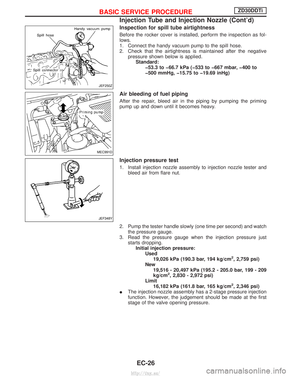
Inspection for spill tube airtightness
Before the rocker cover is installed, perform the inspection as fol-
lows.
1. Connect the handy vacuum pump to the spill hose.
2. Check that the airtightness is maintained after the negativepressure shown below is applied.Standard: þ53.3 to þ66.7 kPa (þ533 to þ667 mbar, þ400 to
þ500 mmHg, þ15.75 to þ19.69 inHg)
Air bleeding of fuel piping
After the repair, bleed air in the piping by pumping the priming
pump up and down until it becomes heavy.
Injection pressure test
1. Install injection nozzle assembly to injection nozzle tester andbleed air from flare nut.
2. Pump the tester handle slowly (one time per second) and watch the pressure gauge.
3. Read the pressure gauge when the injection pressure just starts dropping.Initial injection pressure: Used19,026 kPa (190.3 bar, 194 kg/cm
2, 2,759 psi)
New 19,516 - 20,497 kPa (195.2 - 205.0 bar, 199 - 209
kg/cm
2, 2,830 - 2,972 psi)
Limit 16,182 kPa (161.8 bar, 165 kg/cm
2, 2,346 psi)
I The injection nozzle assembly has a 2-stage pressure injection
function. However, the judgement should be made at the first
stage of the valve opening pressure.
JEF250Z
MEC991D
JEF348Y
BASIC SERVICE PROCEDUREZD30DDTi
Injection Tube and Injection Nozzle (Cont'd)
EC-26
http://vnx.su/
Page 303 of 1833

REMOVAL
1. Remove the following:
IEngine coolant draining
I Charge air cooler
I Air inlet pipe
I Throttle body
I Rocker cover
I Oil level gauge guide
I EGR cooler
I EGR guide tube
I EGR volume control solenoid valve
I Fuel hose
I Injection tube
I Radiator upper hose
I Radiator shroud
I Cooling fan
I Drive belt
I Vacuum pipe
I Vacuum pump
2. Move the power steering pump.
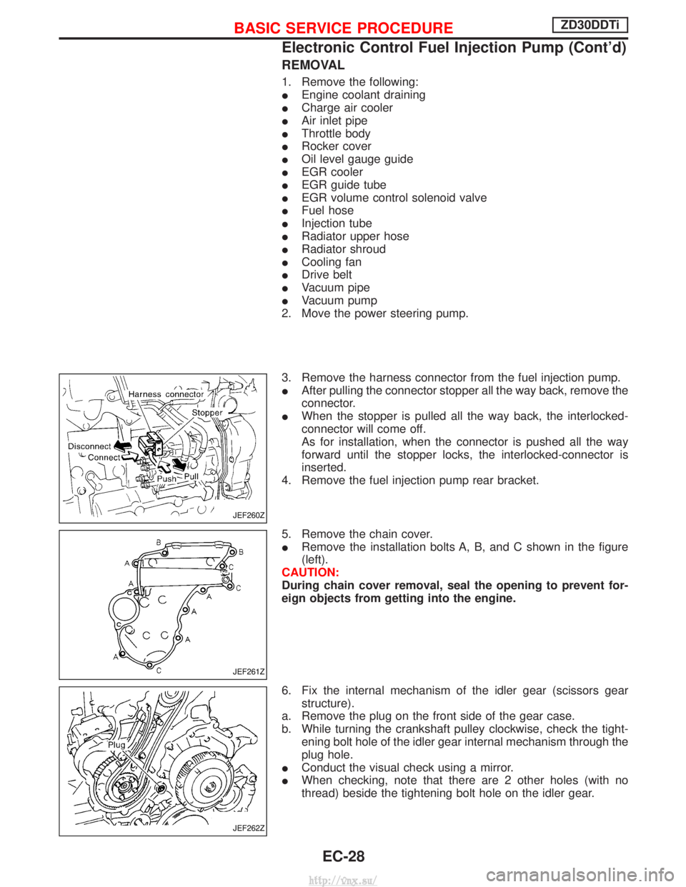
3. Remove the harness connector from the fuel injection pump.
I After pulling the connector stopper all the way back, remove the
connector.
I When the stopper is pulled all the way back, the interlocked-
connector will come off.
As for installation, when the connector is pushed all the way
forward until the stopper locks, the interlocked-connector is
inserted.
4. Remove the fuel injection pump rear bracket.
5. Remove the chain cover.
I Remove the installation bolts A, B, and C shown in the figure
(left).
CAUTION:
During chain cover removal, seal the opening to prevent for-
eign objects from getting into the engine.
6. Fix the internal mechanism of the idler gear (scissors gear structure).
a. Remove the plug on the front side of the gear case.
b. While turning the crankshaft pulley clockwise, check the tight- ening bolt hole of the idler gear internal mechanism through the
plug hole.
I Conduct the visual check using a mirror.
I When checking, note that there are 2 other holes (with no
thread) beside the tightening bolt hole on the idler gear.
JEF260Z
JEF261Z
JEF262Z
BASIC SERVICE PROCEDUREZD30DDTi
Electronic Control Fuel Injection Pump (Cont'd)
EC-28
http://vnx.su/