2004 NISSAN TERRANO warning light
[x] Cancel search: warning lightPage 45 of 1833
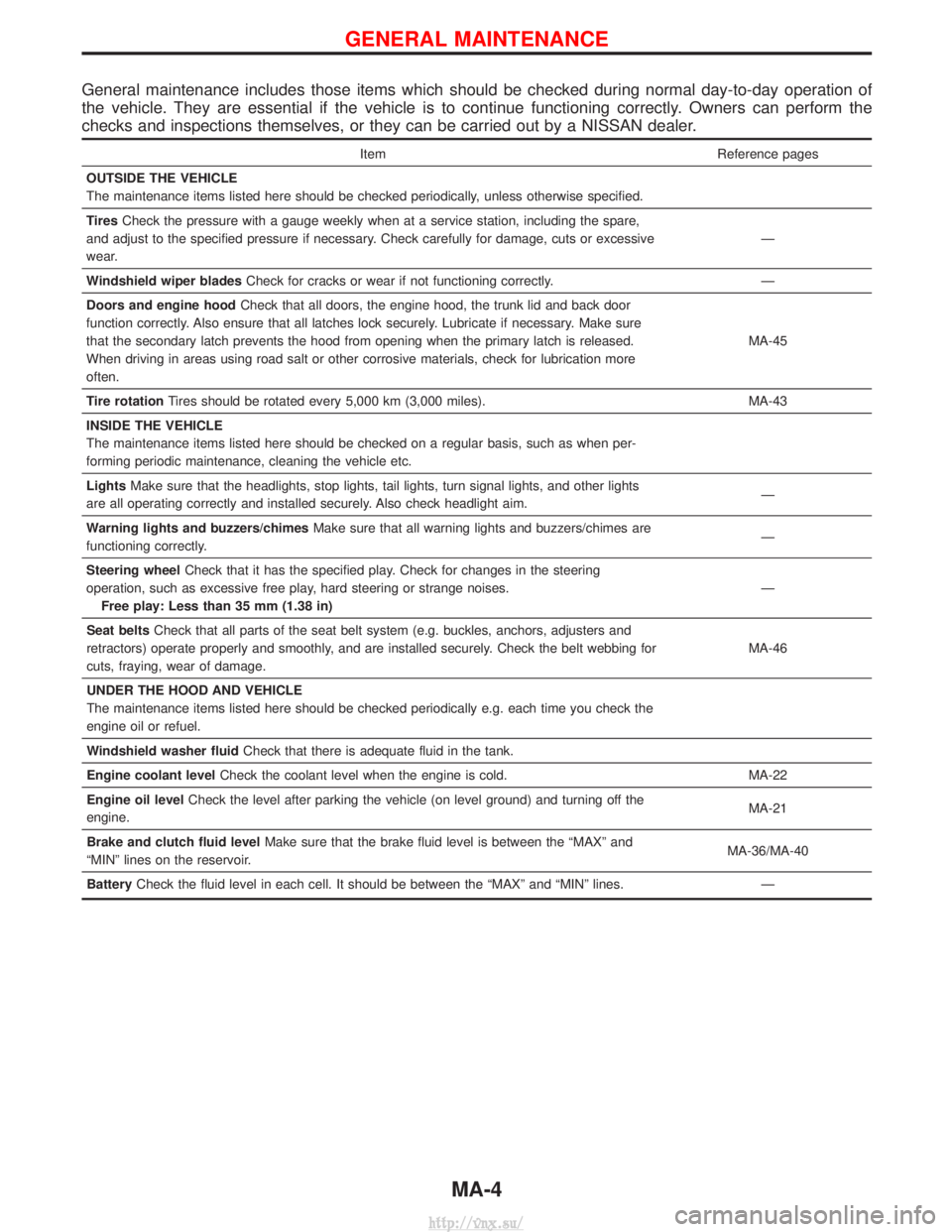
General maintenance includes those items which should be checked during normal day-to-day operation of
the vehicle. They are essential if the vehicle is to continue functioning correctly. Owners can perform the
checks and inspections themselves, or they can be carried out by a NISSAN dealer.
ItemReference pages
OUTSIDE THE VEHICLE
The maintenance items listed here should be checked periodically, unless otherwise specified.
Tires Check the pressure with a gauge weekly when at a service station, including the spare,
and adjust to the specified pressure if necessary. Check carefully for damage, cuts or excessive
wear. Ð
Windshield wiper blades Check for cracks or wear if not functioning correctly. Ð
Doors and engine hood Check that all doors, the engine hood, the trunk lid and back door
function correctly. Also ensure that all latches lock securely. Lubricate if necessary. Make sure
that the secondary latch prevents the hood from opening when the primary latch is released.
When driving in areas using road salt or other corrosive materials, check for lubrication more
often. MA-45
Tire rotation Tires should be rotated every 5,000 km (3,000 miles). MA-43
INSIDE THE VEHICLE
The maintenance items listed here should be checked on a regular basis, such as when per-
forming periodic maintenance, cleaning the vehicle etc.
Lights Make sure that the headlights, stop lights, tail lights, turn signal lights, and other lights
are all operating correctly and installed securely. Also check headlight aim. Ð
Warning lights and buzzers/chimes Make sure that all warning lights and buzzers/chimes are
functioning correctly. Ð
Steering wheel Check that it has the specified play. Check for changes in the steering
operation, such as excessive free play, hard steering or strange noises. Free play: Less than 35 mm (1.38 in) Ð
Seat belts Check that all parts of the seat belt system (e.g. buckles, anchors, adjusters and
retractors) operate properly and smoothly, and are installed securely. Check the belt webbing for
cuts, fraying, wear of damage. MA-46
UNDER THE HOOD AND VEHICLE
The maintenance items listed here should be checked periodically e.g. each time you check the
engine oil or refuel.
Windshield washer fluid Check that there is adequate fluid in the tank.
Engine coolant level Check the coolant level when the engine is cold. MA-22
Engine oil level Check the level after parking the vehicle (on level ground) and turning off the
engine. MA-21
Brake and clutch fluid level Make sure that the brake fluid level is between the ªMAXº and
ªMINº lines on the reservoir. MA-36/MA-40
Battery Check the fluid level in each cell. It should be between the ªMAXº and ªMINº lines. Ð
GENERAL MAINTENANCE
MA-4
http://vnx.su/
Page 63 of 1833
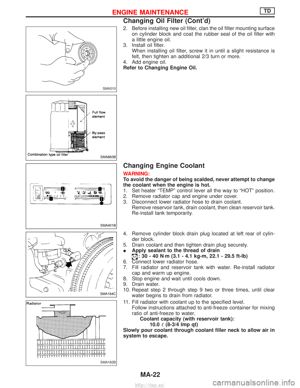
2. Before installing new oil filter, clan the oil filter mounting surfaceon cylinder block and coat the rubber seal of the oil filter with
a little engine oil.
3. Install oil filter. When installing oil filter, screw it in until a slight resistance is
felt, then tighten an additional 2/3 turn or more.
4. Add engine oil.
Refer to Changing Engine Oil.
Changing Engine Coolant
WARNING:
To avoid the danger of being scalded, never attempt to change
the coolant when the engine is hot.
1. Set heater ªTEMPº control lever all the way to ªHOTº position.
2. Remove radiator cap and engine under cover.
3. Disconnect lower radiator hose to drain coolant. Remove reservoir tank, drain coolant, then clean reservoir tank.
Re-install tank temporarily.
4. Remove cylinder block drain plug located at left rear of cylin- der block.
5. Drain coolant and then tighten drain plug securely.
I Apply sealant to the thread of drain
:30-40N ×m (3.1 - 4.1 kg-m, 22.1 - 29.5 ft-lb)
6. Connect lower radiator hose.
7. Fill radiator and reservoir tank with water. Re-install radiator cap and warm up engine.
8. Stop engine and wait until cools down.
9. Drain water.
10. Repeat step 2 through step 9 two or three times, until clear water begins to drain from radiator.
11. Fill radiator with coolant up to the specified level. Follow instructions attached to anti-freeze container for mixing
ratio of anti-freeze to water.Coolant capacity (with reservoir tank): 10.0 (8-3/4 Imp qt)
Slowly pour coolant through coolant filler neck to allow air in
system to escape.
SMA010
SMA860B
SMA401B
SMA164C
SMA182B
ENGINE MAINTENANCETD
Changing Oil Filter (Cont'd)
MA-22
http://vnx.su/
Page 309 of 1833
IIf the battery is disconnected, the emission-related diagnostic information will be lost after approx.
24 hours.
I Erasing the emission-related diagnostic information using CONSULT-II is easier and quicker than
switching the diagnostic test mode using the data link connector.
NATS (Nissan Anti-Theft System)
IIf the security indicator lights up with the ignition switch in
the ªONº position or ªNATS MALFUNCTIONº is displayed
on ªSELF-DIAG RESULTSº screen, perform self-diagnostic
results mode with CONSULT-II using NATS program card.
Refer to ªNATS (Nissan Anti-Theft System)º in EL section.
I Confirm no self-diagnostic results of NATS is displayed
before touching ªERASEº in ªSELF-DIAG RESULTSº mode
with CONSULT-II.
I When replacing ECM, initialization of NATS system and
registration of all NATS ignition key IDs must be carried out
with CONSULT-II using NATS program card.
Therefore, be sure to receive all keys from vehicle owner.
Regarding the procedures of NATS initialization and NATS
ignition key ID registration, refer to CONSULT-II operation
manual, NATS.
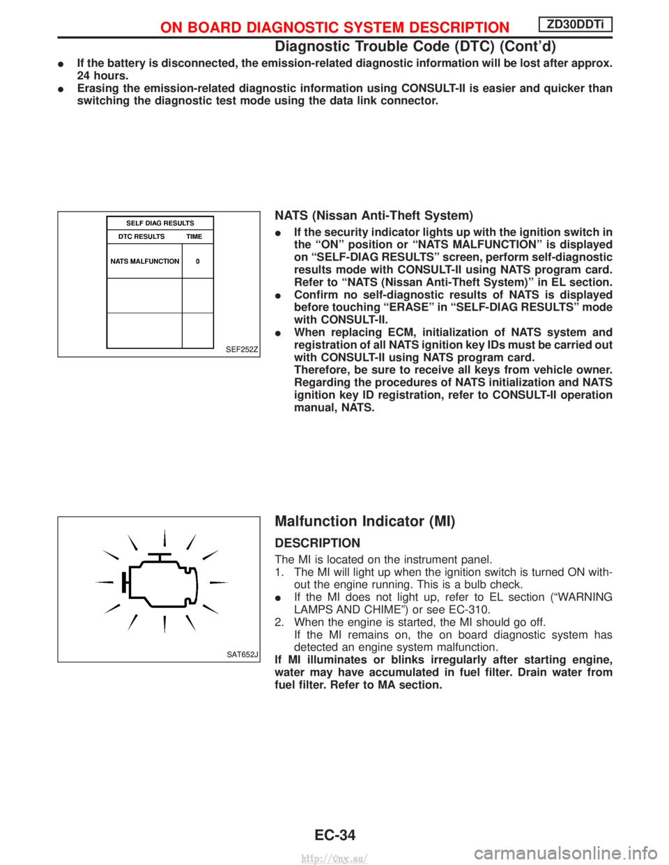
Malfunction Indicator (MI)
DESCRIPTION
The MI is located on the instrument panel.
1. The MI will light up when the ignition switch is turned ON with-
out the engine running. This is a bulb check.
I If the MI does not light up, refer to EL section (ªWARNING
LAMPS AND CHIMEº) or see EC-310.
2. When the engine is started, the MI should go off. If the MI remains on, the on board diagnostic system has
detected an engine system malfunction.
If MI illuminates or blinks irregularly after starting engine,
water may have accumulated in fuel filter. Drain water from
fuel filter. Refer to MA section.
SEF252Z
SAT652J
ON BOARD DIAGNOSTIC SYSTEM DESCRIPTIONZD30DDTi
Diagnostic Trouble Code (DTC) (Cont'd)
EC-34
http://vnx.su/
Page 310 of 1833
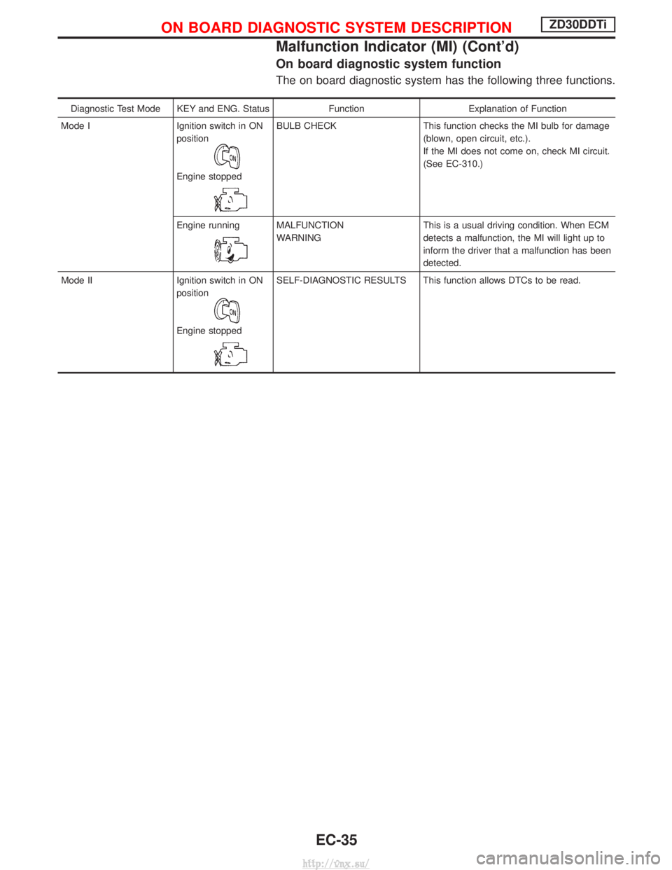
On board diagnostic system function
The on board diagnostic system has the following three functions.
Diagnostic Test Mode KEY and ENG. StatusFunctionExplanation of Function
Mode I Ignition switch in ON
position
Engine stopped
BULB CHECK This function checks the MI bulb for damage
(blown, open circuit, etc.).
If the MI does not come on, check MI circuit.
(See EC-310.)
Engine running
MALFUNCTION
WARNING This is a usual driving condition. When ECM
detects a malfunction, the MI will light up to
inform the driver that a malfunction has been
detected.
Mode II Ignition switch in ON position
Engine stopped
SELF-DIAGNOSTIC RESULTS This function allows DTCs to be read.
ON BOARD DIAGNOSTIC SYSTEM DESCRIPTIONZD30DDTi
Malfunction Indicator (MI) (Cont'd)
EC-35
http://vnx.su/
Page 620 of 1833
How to Erase DTC (Without CONSULT-II)
1. If the ignition switch stays ªONº after repair work, be sure to turn ignition switch ªOFFº once. Wait at least5 seconds and then turn it ªONº (engine stopped) again.
2. Change the diagnostic test mode from Mode II to Mode I by using the data link connector. (See EC-346.)
The emission related diagnostic information in the ECM can be erased by changing the diagnostic test mode.
I If the battery is disconnected, the emission-related diagnostic information will be lost after approx.
24 hours.
I Erasing the emission-related diagnostic information using CONSULT-II is easier and quicker than
switching the diagnostic test mode using the data link connector.
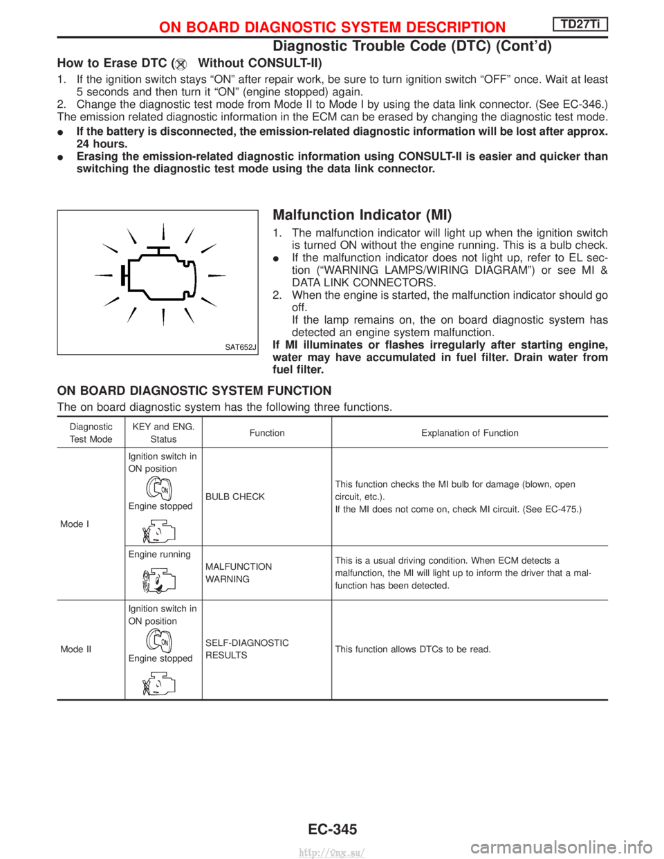
Malfunction Indicator (MI)
1. The malfunction indicator will light up when the ignition switch
is turned ON without the engine running. This is a bulb check.
I If the malfunction indicator does not light up, refer to EL sec-
tion (ªWARNING LAMPS/WIRING DIAGRAMº) or see MI &
DATA LINK CONNECTORS.
2. When the engine is started, the malfunction indicator should go off.
If the lamp remains on, the on board diagnostic system has
detected an engine system malfunction.
If MI illuminates or flashes irregularly after starting engine,
water may have accumulated in fuel filter. Drain water from
fuel filter.
ON BOARD DIAGNOSTIC SYSTEM FUNCTION
The on board diagnostic system has the following three functions.
Diagnostic
Test Mode KEY and ENG.
Status Function Explanation of Function
Mode I Ignition switch in
ON position
Engine stoppedBULB CHECK
This function checks the MI bulb for damage (blown, open
circuit, etc.).
If the MI does not come on, check MI circuit. (See EC-475.)
Engine running
MALFUNCTION
WARNING This is a usual driving condition. When ECM detects a
malfunction, the MI will light up to inform the driver that a mal-
function has been detected.
Mode II Ignition switch in
ON position
Engine stopped
SELF-DIAGNOSTIC
RESULTS
This function allows DTCs to be read.
SAT652J
ON BOARD DIAGNOSTIC SYSTEM DESCRIPTIONTD27Ti
Diagnostic Trouble Code (DTC) (Cont'd)
EC-345
http://vnx.su/
Page 911 of 1833
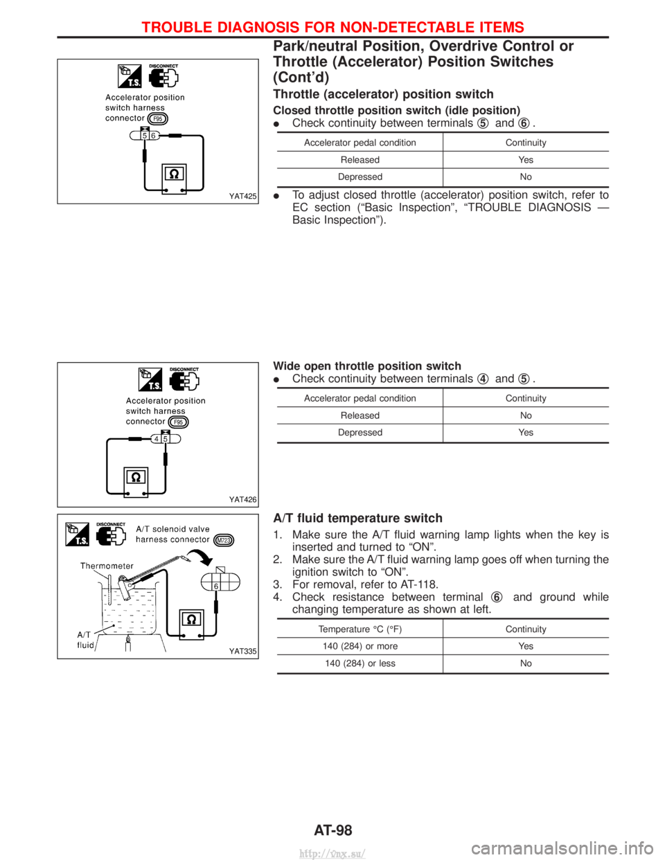
Throttle (accelerator) position switch
Closed throttle position switch (idle position)
ICheck continuity between terminals q
5andq6.
Accelerator pedal condition
Continuity
Released Yes
Depressed No
ITo adjust closed throttle (accelerator) position switch, refer to
EC section (ªBasic Inspectionº, ªTROUBLE DIAGNOSIS Ð
Basic Inspectionº).
Wide open throttle position switch
I Check continuity between terminals q
4andq5.
Accelerator pedal condition
Continuity
Released No
Depressed Yes
A/T fluid temperature switch
1. Make sure the A/T fluid warning lamp lights when the key is
inserted and turned to ªONº.
2. Make sure the A/T fluid warning lamp goes off when turning the ignition switch to ªONº.
3. For removal, refer to AT-118.
4. Check resistance between terminal q
6and ground while
changing temperature as shown at left.
Temperature ÉC (ÉF) Continuity
140 (284) or more Yes
140 (284) or less No
YAT425
YAT426
YAT335
TROUBLE DIAGNOSIS FOR NON-DETECTABLE ITEMS
Park/neutral Position, Overdrive Control or
Throttle (Accelerator) Position Switches
(Cont'd)
AT-98
http://vnx.su/
Page 1205 of 1833
Purpose
The Anti-lock Brake System (ABS) with an integrated Electronic Brake force Distribution (EBD) system con-
sists of electronic and hydraulic components. It allows you to control the braking force so that wheel lock can
be avoided during braking.
The advantages of ABS with EBD
1) Better tracking performance through improved steering wheel control.
2) Improved maneuverability and safer vehicle control.
3) Improved vehicle stability by preventing flat spins.
4) Shorter stopping distance and optimal utilisation of the rear brakes under many different circumstances.
Operation
IABS with EBD has self-test capabilities. The ABS warning lamp is illuminated for 1 second each time the
ignition switch is turned ªONº. After the engine is started, the ABS warning lamp turns off. An ABS self-test
is performed the first time the vehicle reaches 6 km/h (4 MPH) to ensure the system is operational. A
mechanical noise may be heard as the ABS performs this self-test and is a normal part of the self-test
feature. If a malfunction is detected during this check, the ABS warning lamp will stay on.
During the self-test, it also performs a EBD check when it detects a failure the ABS warning light will go
on simultaneously with the brake warning light and an audible sound will sound constantly.
I EBD system will only operate when the ABS is not in active status and it uses the inlet valves of ABS con-
trol unit to limit the pressure to the rear wheels when they tend to go into slip.
I When the vehicle speed is less than 10 km/h (6 MPH) the ABS system does not operate.
I While driving, a mechanical noise may be heard during ABS operation, this is a normal system condition.
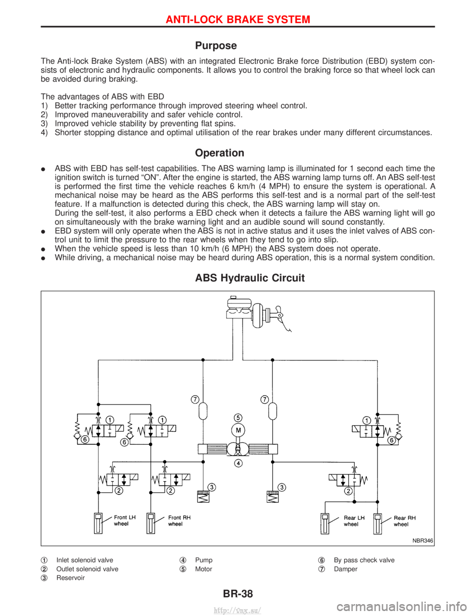
ABS Hydraulic Circuit
q1Inlet solenoid valve
q
2Outlet solenoid valve
q
3Reservoir q
4Pump
q
5Motor q
6By pass check valve
q
7Damper
NBR346
ANTI-LOCK BRAKE SYSTEM
BR-38
http://vnx.su/
Page 1206 of 1833
System Description
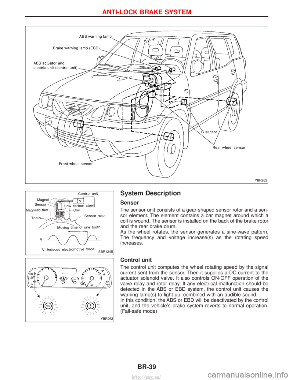
Sensor
The sensor unit consists of a gear-shaped sensor rotor and a sen-
sor element. The element contains a bar magnet around which a
coil is wound. The sensor is installed on the back of the brake rotor
and the rear brake drum.
As the wheel rotates, the sensor generates a sine-wave pattern.
The frequency and voltage increase(s) as the rotating speed
increases.
Control unit
The control unit computes the wheel rotating speed by the signal
current sent from the sensor. Then it supplies a DC current to the
actuator solenoid valve. It also controls ON-OFF operation of the
valve relay and rotor relay. If any electrical malfunction should be
detected in the ABS or EBD system, the control unit causes the
warning lamp(s) to light up, combined with an audible sound.
In this condition, the ABS or EBD will be deactivated by the control
unit, and the vehicle's brake system reverts to normal operation.
(Fail-safe mode)
YBR262
SBR124B
YBR263
ANTI-LOCK BRAKE SYSTEM
BR-39
http://vnx.su/