2004 NISSAN TERRANO length
[x] Cancel search: lengthPage 33 of 1833
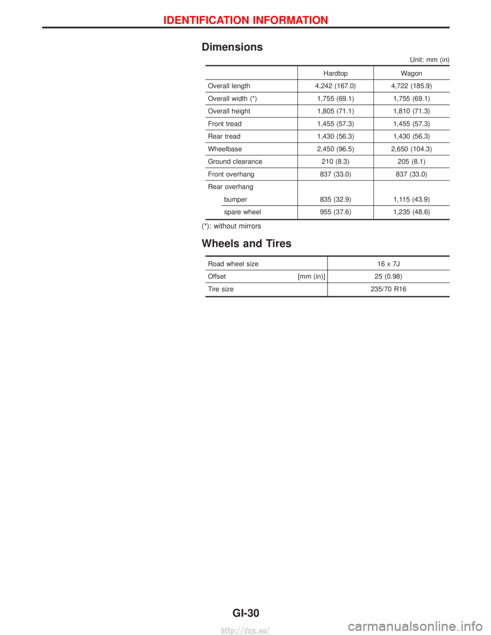
Dimensions
Unit: mm (in)
HardtopWagon
Overall length 4,242 (167.0) 4,722 (185.9)
Overall width (*) 1,755 (69.1) 1,755 (69.1)
Overall height 1,805 (71.1) 1,810 (71.3)
Front tread 1,455 (57.3) 1,455 (57.3)
Rear tread 1,430 (56.3) 1,430 (56.3)
Wheelbase 2,450 (96.5) 2,650 (104.3)
Ground clearance 210 (8.3) 205 (8.1)
Front overhang 837 (33.0) 837 (33.0)
Rear overhang bumper 835 (32.9) 1,115 (43.9)
spare wheel 955 (37.6) 1,235 (48.6)
(*): without mirrors
Wheels and Tires
Road wheel size 16 x 7J
Offset [mm (in)]25 (0.98)
Tire size 235/70 R16
IDENTIFICATION INFORMATION
GI-30
http://vnx.su/
Page 70 of 1833

Removal
WATER PUMP, ALTERNATOR AND AIR CONDITIONER
BELT
1. Remove radiator shroud.
2. Contract and hold the auto tensioner using the following proce-dure.
a. Securely hold the 19 mm (0.75 in) hexagonal portion A of auto tensioner with a closed wrench.
I Preferably use a tool with a handhold of 500 mm (19.69 in) or
more in length.
I No bolts or nuts are required to be loosened during the opera-
tion.
b. Turn the hexagonal portion A in the direction shown by the arrow to contract the damper unit of the auto tensioner.
CAUTION:
I Because the tensioner has a high tension, it shall be
securely held and turned with a closed wrench.
I Because the hexagonal portion A of the tensioner is made
of aluminum and may be damaged by sudden input, turn
it slowly according to the contraction of the damper unit.
3. Remove the belt from the alternator pulley first, and then remove it from the other pulleys.
I If the tensioner is not held firmly, your finger may get caught
between the belt and the pulleys. Confirm the holding of the
tensioner, and then hold the belt side in the place away from
the pulleys to attach or remove the belt, paying attention to
prevent your finger from being caught.
CAUTION:
I When handling the belt, pay attention to prevent the oil or
coolant from adhering to the belt.
I Do not distort or bend the belt intensively.
Installation
IInstall the belt in the reverse order of removal.
I After installation of the belt, confirm that the belt engages the
pulleys securely.
I Depending on the engagement between the belt and the idler
pulley, noise (belt noise) may be heard when the engine is
started just after installation. This noise will stop with time.
Changing Engine Oil
WARNING:
IBe careful not to burn yourself, as engine oil is hot.
I Prolonged and repeated contact with used engine oil may
cause skin cancer; try to avoid direct skin contact with
used oil. If skin contact is made, wash thoroughly with
soap or hand cleaner as soon as possible.
1. Warm up engine, and check for oil leakage from engine com- ponents.
2. Remove drain plug and oil filler cap.
SMA101D
ENGINE MAINTENANCEZD
MA-29
http://vnx.su/
Page 152 of 1833
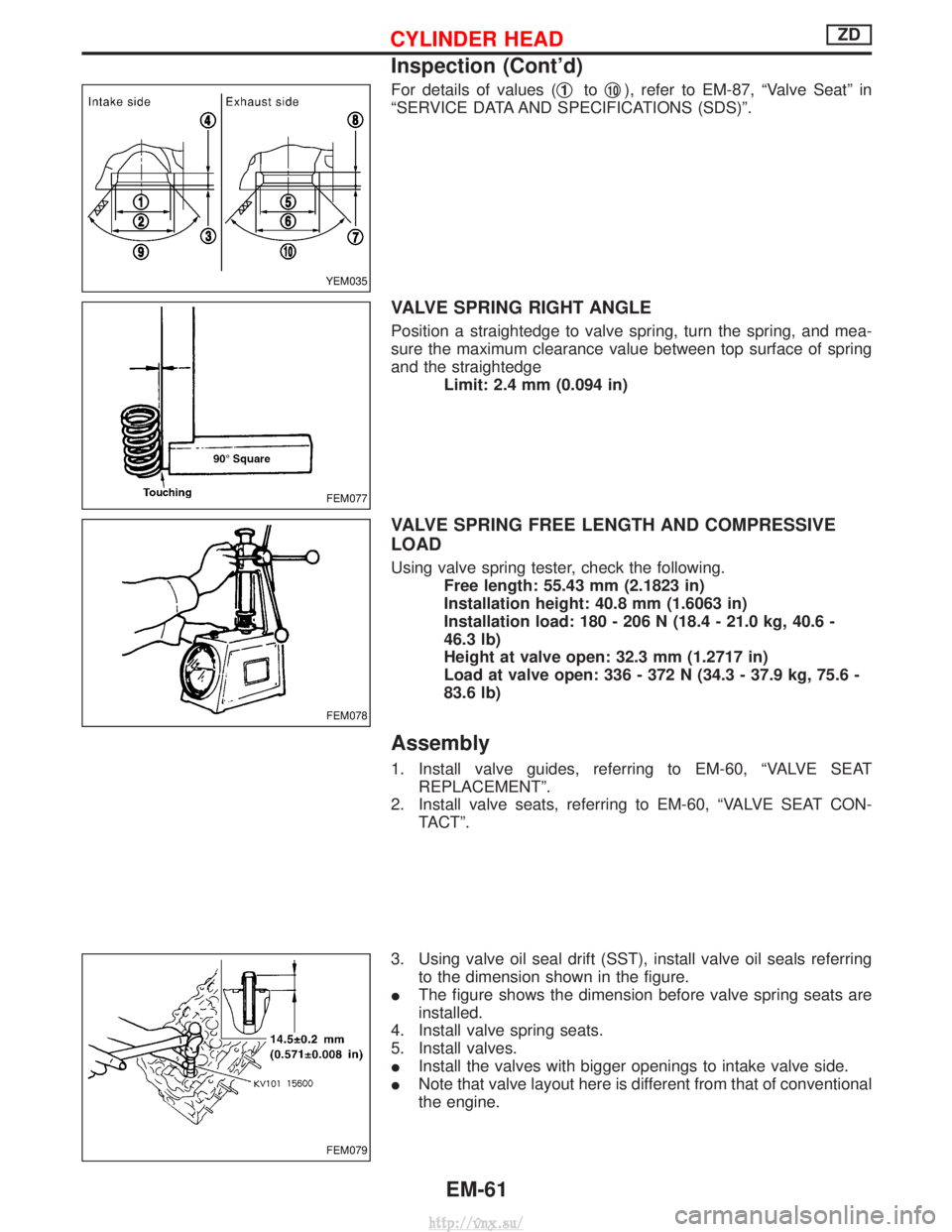
For details of values (q1toq10), refer to EM-87, ªValve Seatº in
ªSERVICE DATA AND SPECIFICATIONS (SDS)º.
VALVE SPRING RIGHT ANGLE
Position a straightedge to valve spring, turn the spring, and mea-
sure the maximum clearance value between top surface of spring
and the straightedge Limit: 2.4 mm (0.094 in)
VALVE SPRING FREE LENGTH AND COMPRESSIVE
LOAD
Using valve spring tester, check the following.Free length: 55.43 mm (2.1823 in)
Installation height: 40.8 mm (1.6063 in)
Installation load: 180 - 206 N (18.4 - 21.0 kg, 40.6 -
46.3 lb)
Height at valve open: 32.3 mm (1.2717 in)
Load at valve open: 336 - 372 N (34.3 - 37.9 kg, 75.6 -
83.6 lb)
Assembly
1. Install valve guides, referring to EM-60, ªVALVE SEATREPLACEMENTº.
2. Install valve seats, referring to EM-60, ªVALVE SEAT CON- TACTº.
3. Using valve oil seal drift (SST), install valve oil seals referring to the dimension shown in the figure.
I The figure shows the dimension before valve spring seats are
installed.
4. Install valve spring seats.
5. Install valves.
I Install the valves with bigger openings to intake valve side.
I Note that valve layout here is different from that of conventional
the engine.
YEM035
FEM077
FEM078
FEM079
CYLINDER HEADZD
Inspection (Cont'd)
EM-61
http://vnx.su/
Page 171 of 1833

Assembly
1. Blow air sufficiently to inside coolant passage, oil passage,crankcase, and cylinder bore to remove foreign matter.
2. Install main bearings and thrust bearings.
1) Remove contamination, dust and oil from bearing mounting positions on cylinder block and main bearing caps.
2) Install thrust bearings on both sides of No. 4 housing on cylin- der block.
I Install thrust bearings with oil groove facing to crankshaft arm
(outside).
3) Being careful with the direction, install main bearings.
I Install main bearings with the oil holes and grooves onto the
cylinder block side, and those without oil holes and grooves
onto the lower cylinder block side.
I While installing bearings, apply engine oil to bearing surfaces
(inside). Do not apply oil to rear surfaces, but clean them com-
pletely.
I Align stopper notches on bearings to install them.
I Check that the oil holes on the cylinder block body are mated
with the oil hole positions on the bearings.
3. Install crankshaft to cylinder block.
I While rotating crankshaft by hand, check for smooth rotation.
4. Install lower cylinder block.
I Apply a continuous bead of liquid gasket to lower cylinder block
as shown in the figure.
I Using slots on engine sub-attachment, install the lower cylinder
block to the cylinder block, avoiding interference of dowel pins.
5. Tighten lower cylinder mounting bolts to the torque shown below in 3 consecutive steps in the order shown in the figure.
Unit: N ×m (kg-m, ft-lb)
Main bolt (Nos. 1 - 10) Sub-bolt (Nos. 11 - 20)
1st 20 (2.0, 14) 98 (10, 72)
2nd 98 (10, 72) 20 (2.0, 14)
3rd 167 - 176 (17 - 18, 123 - 130) 40 - 46 (4.0 - 4.7, 29 - 33)
I Sub-bolt No. 17 has shorter length than that of other sub-bolts.
FEM126
FEM127
FEM128
FEM092
CYLINDER BLOCKZD
EM-80
http://vnx.su/
Page 173 of 1833
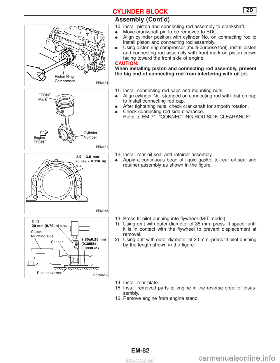
10. Install piston and connecting rod assembly to crankshaft.
IMove crankshaft pin to be removed to BDC.
I Align cylinder position with cylinder No. on connecting rod to
install piston and connecting rod assembly.
I Using piston ring compressor (multi-purpose tool), install piston
and connecting rod assembly with front mark on piston crown
facing toward the front side of engine.
CAUTION:
When installing piston and connecting rod assembly, prevent
the big end of connecting rod from interfering with oil jet.
11. Install connecting rod caps and mounting nuts.
I Align cylinder No. stamped on connecting rod with that on cap
to install connecting rod cap.
I After tightening nuts, check crankshaft for smooth rotation.
I Check connecting rod side clearance.
Refer to EM-71, ªCONNECTING ROD SIDE CLEARANCEº.
12. Install rear oil seal and retainer assembly.
I Apply a continuous bead of liquid gasket to rear oil seal and
retainer assembly as shown in the figure.
13. Press fit pilot bushing into flywheel (M/T model).
1) Using drift with outer diameter of 35 mm, press fit spacer until it is in contact with the flywheel to prevent displacement at
removal.
2) Using drift with outer diameter of 20 mm, press fit pilot bushing by the length shown in the figure.
14. Install rear plate.
15. Install removed parts to engine in the reverse order of disas- sembly.
16. Remove engine from engine stand.
FEM134
FEM131
FEM053
SEM366G
CYLINDER BLOCKZD
Assembly (Cont'd)
EM-82
http://vnx.su/
Page 176 of 1833
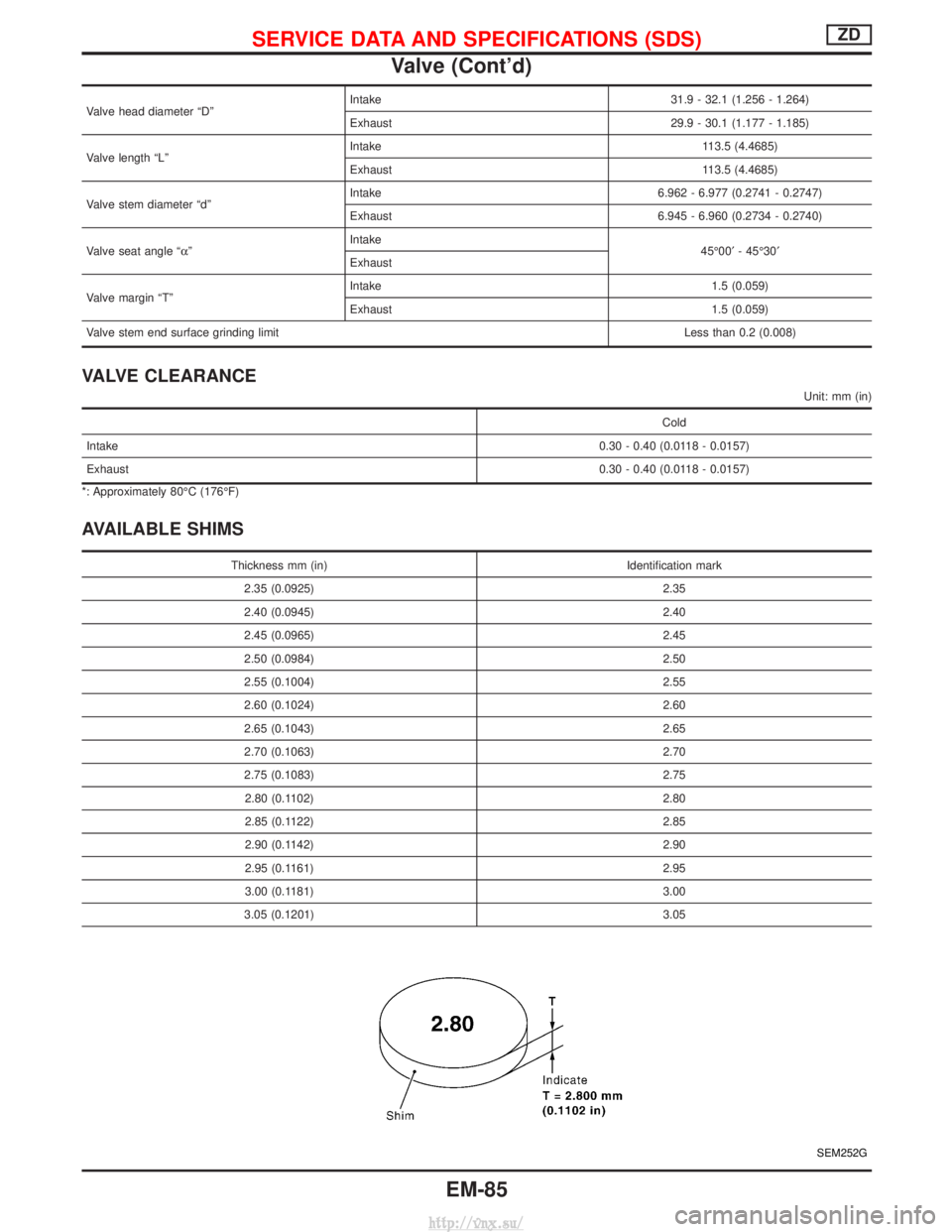
Valve head diameter ªDºIntake 31.9 - 32.1 (1.256 - 1.264)
Exhaust 29.9 - 30.1 (1.177 - 1.185)
Valve length ªLº Intake 113.5 (4.4685)
Exhaust 113.5 (4.4685)
Valve stem diameter ªdº Intake 6.962 - 6.977 (0.2741 - 0.2747)
Exhaust 6.945 - 6.960 (0.2734 - 0.2740)
Valve seat angle ªa º Intake
45É00¢- 45É30¢
Exhaust
Valve margin ªTº Intake 1.5 (0.059)
Exhaust 1.5 (0.059)
Valve stem end surface grinding limit Less than 0.2 (0.008)
VALVE CLEARANCE
Unit: mm (in)
Cold
Intake 0.30 - 0.40 (0.0118 - 0.0157)
Exhaust 0.30 - 0.40 (0.0118 - 0.0157)
*: Approximately 80ÉC (176ÉF)
AVAILABLE SHIMS
Thickness mm (in) Identification mark
2.35 (0.0925) 2.35
2.40 (0.0945) 2.40
2.45 (0.0965) 2.45
2.50 (0.0984) 2.50
2.55 (0.1004) 2.55
2.60 (0.1024) 2.60
2.65 (0.1043) 2.65
2.70 (0.1063) 2.70
2.75 (0.1083) 2.75
2.80 (0.1102) 2.80
2.85 (0.1122) 2.85
2.90 (0.1142) 2.90
2.95 (0.1161) 2.95
3.00 (0.1181) 3.00
3.05 (0.1201) 3.05
SEM252G
SERVICE DATA AND SPECIFICATIONS (SDS)ZD
Valve (Cont'd)
EM-85
http://vnx.su/
Page 177 of 1833
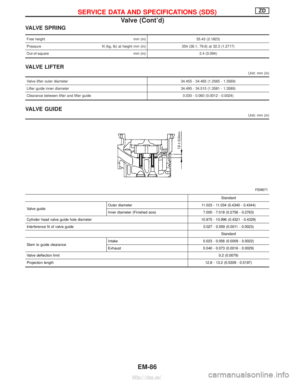
VALVE SPRING
Free heightmm (in)55.43 (2.1823)
Pressure N (kg, lb) at height mm (in) 354 (36.1, 79.6) at 32.3 (1.2717)
Out-of-square mm (in) 2.4 (0.094)
VALVE LIFTER
Unit: mm (in)
Valve lifter outer diameter 34.455 - 34.465 (1.3565 - 1.3569)
Lifter guide inner diameter 34.495 - 34.515 (1.3581 - 1.3589)
Clearance between lifter and lifter guide 0.030 - 0.060 (0.0012 - 0.0024)
VALVE GUIDE
Unit: mm (in)
FEM071
Standard
Valve guide Outer diameter 11.023 - 11.034 (0.4340 - 0.4344)
Inner diameter (Finished size) 7.000 - 7.018 (0.2756 - 0.2763)
Cylinder head valve guide hole diameter 10.975 - 10.996 (0.4321 - 0.4329)
Interference fit of valve guide 0.027 - 0.059 (0.0011 - 0.0023)
Standard
Stem to guide clearance Intake 0.023 - 0.056 (0.0009 - 0.0022)
Exhaust 0.040 - 0.073 (0.0016 - 0.0029)
Valve deflection limit 0.2 (0.0079)
Projection length 12.8 - 13.2 (0.5309 - 0.5197)
SERVICE DATA AND SPECIFICATIONS (SDS)ZD
Valve (Cont'd)
EM-86
http://vnx.su/
Page 220 of 1833
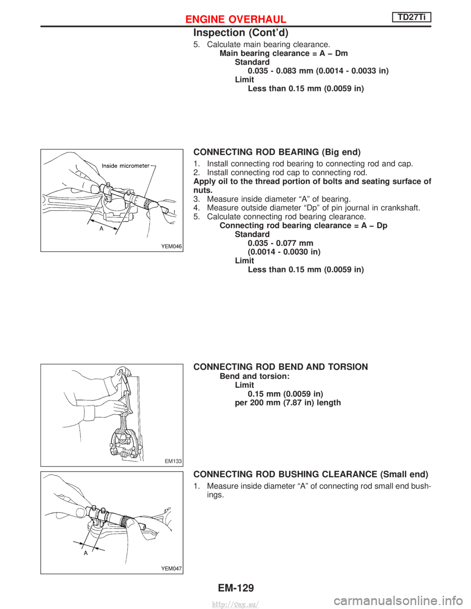
5. Calculate main bearing clearance.Main bearing clearance = A þ DmStandard0.035 - 0.083 mm (0.0014 - 0.0033 in)
Limit Less than 0.15 mm (0.0059 in)
CONNECTING ROD BEARING (Big end)
1. Install connecting rod bearing to connecting rod and cap.
2. Install connecting rod cap to connecting rod.
Apply oil to the thread portion of bolts and seating surface of
nuts.
3. Measure inside diameter ªAº of bearing.
4. Measure outside diameter ªDpº of pin journal in crankshaft.
5. Calculate connecting rod bearing clearance. Connecting rod bearing clearance = A þ DpStandard0.035 - 0.077 mm
(0.0014 - 0.0030 in)
Limit Less than 0.15 mm (0.0059 in)
CONNECTING ROD BEND AND TORSION
Bend and torsion: Limit0.15 mm (0.0059 in)
per 200 mm (7.87 in) length
CONNECTING ROD BUSHING CLEARANCE (Small end)
1. Measure inside diameter ªAº of connecting rod small end bush- ings.
YEM046
EM133
YEM047
ENGINE OVERHAULTD27Ti
Inspection (Cont'd)
EM-129
http://vnx.su/