2004 NISSAN TERRANO Ic regulator
[x] Cancel search: Ic regulatorPage 38 of 1833

***: Not applicable
NEW TERMNEW ACRONYM/
ABBREVIATION OLD TERM
Exhaust gas recirculation temperature sensor EGR temperature sensor Exhaust gas temperature sensor
Flash electrically erasable programmable read
only memory FEEPROM ***
Flash erasable programmable read only memory FEPROM ***
Flexible fuel sensor FFS ***
Flexible fuel system FF system ***
Heated Oxygen sensor HO
2S Exhaust gas sensor
Idle air control system IAC systemIdle speed control
Idle air control valve-air regulator IACV-air regulatorAir regulator
Idle air control valve-auxiliary air control valve IACV-AAC valve Auxiliary air control (AAC) valve
Idle air control valve-FICD solenoid valve IACV-FICD solenoid valve FICD solenoid valve
Idle air control valve-idle up control solenoid
valve IACV-idle up control solenoid
valve
Idle up control solenoid valve
Idle speed control-FI pot ISC-FI potFI pot
Idle speed control system ISC system***
Ignition control module ICM***
Indirect fuel injection system IFI system***
Intake air temperature sensor IATS Air temperature sensor
Knock *** Detonation
Knock sensor KS Detonation sensor
Malfunction indicator MI Check engine light
Manifold absolute pressure MAP ***
Manifold absolute pressure sensor MAPS ***
Manifold differential pressure MDP ***
Manifold differential pressure sensor MDPS ***
Manifold surface temperature MST ***
Manifold surface temperature sensor MSTS ***
Manifold vacuum zone MVZ ***
Manifold vacuum zone sensor MVZS ***
Mass air flow sensor MAFS Air flow meter
Mixture control solenoid valve MC solenoid valve Air-fuel control solenoid valve
Multiport fuel injection system MFI system Fuel injection control
Neutral position switch *** Neutral switch
Non-volatile random access memory NVRAM ***
On-board diagnostic system OBD system Self-diagnosis
Open loop OL Open loop
Oxidation catalyst OC Catalyst
Oxidation catalytic converter system OC system ***
Oxygen sensor O
2S Exhaust gas sensor
Park position switch ***Park switch
Park/neutral position switch PNP switch Park/neutral switch
Periodic trap oxidizer system PTOX system ***
ISO 15031-2 TERMINOLOGY LIST
ISO 15031-2 Terminology List (Cont'd)
GI-35
http://vnx.su/
Page 247 of 1833
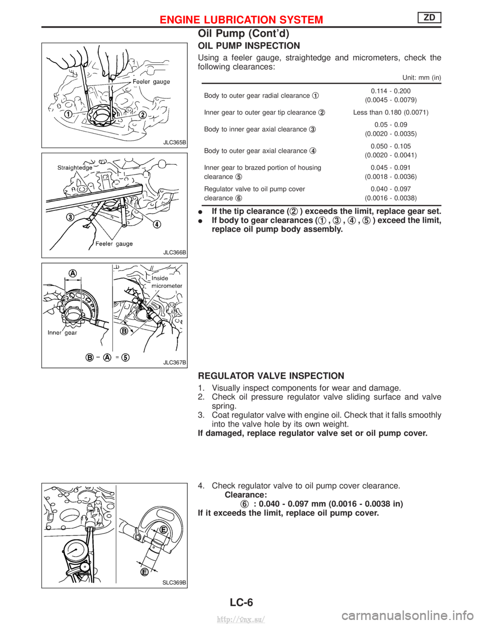
OIL PUMP INSPECTION
Using a feeler gauge, straightedge and micrometers, check the
following clearances:
Unit: mm (in)
Body to outer gear radial clearanceq10.114 - 0.200
(0.0045 - 0.0079)
Inner gear to outer gear tip clearance q
2Less than 0.180 (0.0071)
Body to inner gear axial clearance q
30.05 - 0.09
(0.0020 - 0.0035)
Body to outer gear axial clearance q
40.050 - 0.105
(0.0020 - 0.0041)
Inner gear to brazed portion of housing
clearance q
5
0.045 - 0.091
(0.0018 - 0.0036)
Regulator valve to oil pump cover
clearance q
6
0.040 - 0.097
(0.0016 - 0.0038)
I If the tip clearance ( q2) exceeds the limit, replace gear set.
I If body to gear clearances ( q
1,q3,q4,q5) exceed the limit,
replace oil pump body assembly.
REGULATOR VALVE INSPECTION
1. Visually inspect components for wear and damage.
2. Check oil pressure regulator valve sliding surface and valve spring.
3. Coat regulator valve with engine oil. Check that it falls smoothly into the valve hole by its own weight.
If damaged, replace regulator valve set or oil pump cover.
4. Check regulator valve to oil pump cover clearance. Clearance:q
6: 0.040 - 0.097 mm (0.0016 - 0.0038 in)
If it exceeds the limit, replace oil pump cover.
JLC365B
JLC366B
JLC367B
SLC369B
ENGINE LUBRICATION SYSTEMZD
Oil Pump (Cont'd)
LC-6
http://vnx.su/
Page 258 of 1833
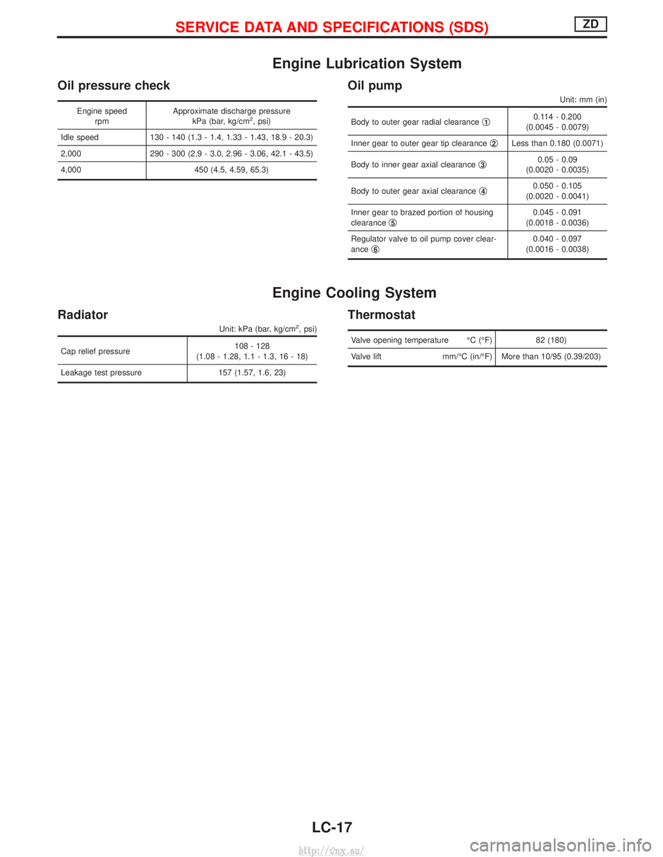
Engine Lubrication System
Oil pressure check
Engine speedrpm Approximate discharge pressure
kPa (bar, kg/cm2, psi)
Idle speed 130 - 140 (1.3 - 1.4, 1.33 - 1.43, 18.9 - 20.3)
2,000 290 - 300 (2.9 - 3.0, 2.96 - 3.06, 42.1 - 43.5)
4,000 450 (4.5, 4.59, 65.3)
Oil pump
Unit: mm (in)
Body to outer gear radial clearance q10.114 - 0.200
(0.0045 - 0.0079)
Inner gear to outer gear tip clearance q
2Less than 0.180 (0.0071)
Body to inner gear axial clearance q
30.05 - 0.09
(0.0020 - 0.0035)
Body to outer gear axial clearance q
40.050 - 0.105
(0.0020 - 0.0041)
Inner gear to brazed portion of housing
clearance q
50.045 - 0.091
(0.0018 - 0.0036)
Regulator valve to oil pump cover clear-
ance q
60.040 - 0.097
(0.0016 - 0.0038)
Engine Cooling System
Radiator
Unit: kPa (bar, kg/cm2, psi)
Cap relief pressure 108 - 128
(1.08 - 1.28, 1.1 - 1.3, 16 - 18)
Leakage test pressure 157 (1.57, 1.6, 23)
Thermostat
Valve opening temperature ÉC (ÉF) 82 (180)
Valve lift mm/ÉC (in/ÉF) More than 10/95 (0.39/203)
SERVICE DATA AND SPECIFICATIONS (SDS)ZD
LC-17
http://vnx.su/
Page 266 of 1833
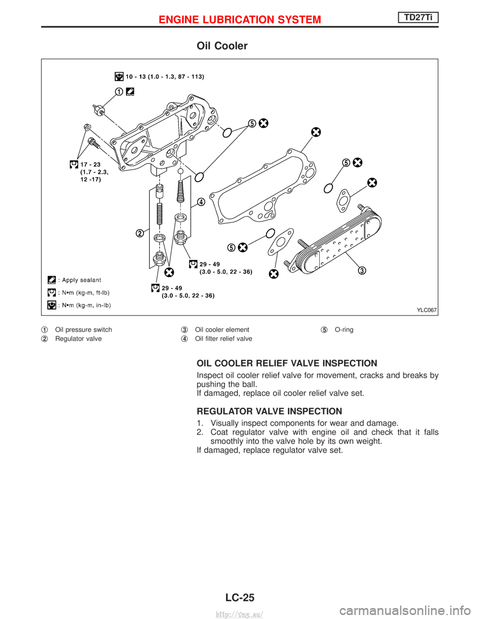
Oil Cooler
q1Oil pressure switch
q
2Regulator valve q
3Oil cooler element
q
4Oil filter relief valve q
5O-ring
OIL COOLER RELIEF VALVE INSPECTION
Inspect oil cooler relief valve for movement, cracks and breaks by
pushing the ball.
If damaged, replace oil cooler relief valve set.
REGULATOR VALVE INSPECTION
1. Visually inspect components for wear and damage.
2. Coat regulator valve with engine oil and check that it falls
smoothly into the valve hole by its own weight.
If damaged, replace regulator valve set.
YLC067
ENGINE LUBRICATION SYSTEMTD27Ti
LC-25
http://vnx.su/
Page 844 of 1833
4. Set parking brake and block wheels.
IContinue to depress brake pedal fully while line pressure
test is being performed at stall speed.
5. Start engine and measure line pressure at idle and stall speed.
I When measuring line pressure at stall speed, follow the
stall test procedure.
Line pressure: Refer to SDS, AT-201.
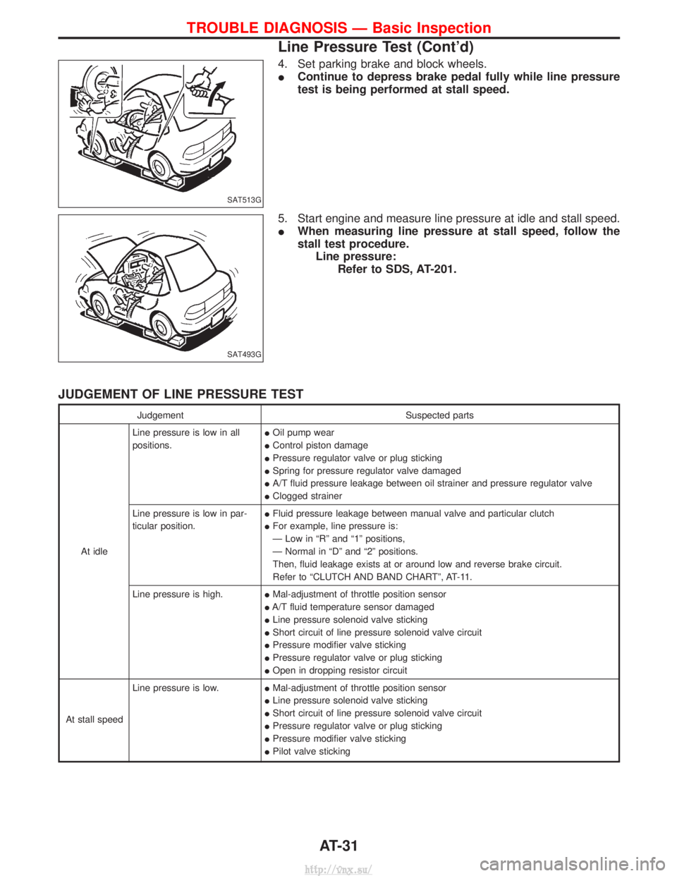
JUDGEMENT OF LINE PRESSURE TEST
Judgement Suspected parts
At idle Line pressure is low in all
positions.
I
Oil pump wear
I Control piston damage
I Pressure regulator valve or plug sticking
I Spring for pressure regulator valve damaged
I A/T fluid pressure leakage between oil strainer and pressure regulator valve
I Clogged strainer
Line pressure is low in par-
ticular position. I
Fluid pressure leakage between manual valve and particular clutch
I For example, line pressure is:
Ð Low in ªRº and ª1º positions,
Ð Normal in ªDº and ª2º positions.
Then, fluid leakage exists at or around low and reverse brake circuit.
Refer to ªCLUTCH AND BAND CHARTº, AT-11.
Line pressure is high. IMal-adjustment of throttle position sensor
I A/T fluid temperature sensor damaged
I Line pressure solenoid valve sticking
I Short circuit of line pressure solenoid valve circuit
I Pressure modifier valve sticking
I Pressure regulator valve or plug sticking
I Open in dropping resistor circuit
At stall speed Line pressure is low.
IMal-adjustment of throttle position sensor
I Line pressure solenoid valve sticking
I Short circuit of line pressure solenoid valve circuit
I Pressure regulator valve or plug sticking
I Pressure modifier valve sticking
I Pilot valve sticking
SAT513G
SAT493G
TROUBLE DIAGNOSIS Ð Basic Inspection
Line Pressure Test (Cont'd)
AT-31
http://vnx.su/
Page 918 of 1833
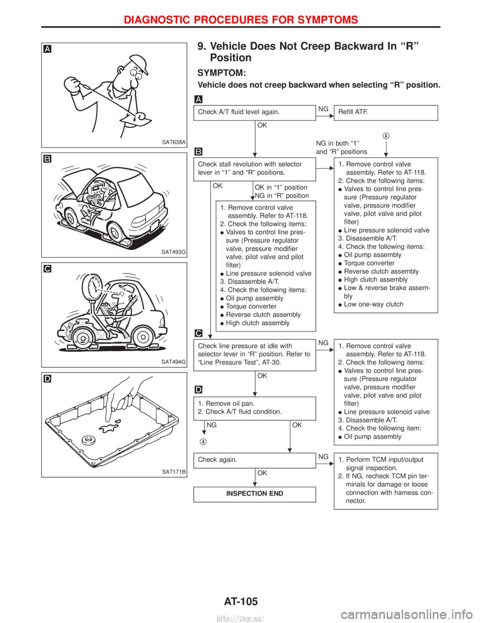
9. Vehicle Does Not Creep Backward In ªRºPosition
SYMPTOM:
Vehicle does not creep backward when selecting ªRº position.
Check A/T fluid level again.
OK
ENG Refill ATF.
qA
NG in both ª1º
and ªRº positions
Check stall revolution with selector
lever in ª1º and ªRº positions.
OK OK in ª1º position
NG in ªRº position
E1. Remove control valve
assembly. Refer to AT-118.
2. Check the following items:
I Valves to control line pres-
sure (Pressure regulator
valve, pressure modifier
valve, pilot valve and pilot
filter)
I Line pressure solenoid valve
3. Disassemble A/T.
4. Check the following items:
I Oil pump assembly
I Torque converter
I Reverse clutch assembly
I High clutch assembly
I Low & reverse brake assem-
bly
I Low one-way clutch
1. Remove control valve
assembly. Refer to AT-118.
2. Check the following items:
I Valves to control line pres-
sure (Pressure regulator
valve, pressure modifier
valve, pilot valve and pilot
filter)
I Line pressure solenoid valve
3. Disassemble A/T.
4. Check the following items:
I Oil pump assembly
I Torque converter
I Reverse clutch assembly
I High clutch assembly
Check line pressure at idle with
selector lever in ªRº position. Refer to
ªLine Pressure Testº, AT-30.
OK
ENG
1. Remove control valve
assembly. Refer to AT-118.
2. Check the following items:
I Valves to control line pres-
sure (Pressure regulator
valve, pressure modifier
valve, pilot valve and pilot
filter)
I Line pressure solenoid valve
3. Disassemble A/T.
4. Check the following item:
I Oil pump assembly
1. Remove oil pan.
2. Check A/T fluid condition.
NG OK
q
A
Check again.
OK
ENG 1. Perform TCM input/output
signal inspection.
2. If NG, recheck TCM pin ter- minals for damage or loose
connection with harness con-
nector.
INSPECTION END
SAT638A
SAT493G
SAT494G
SAT171B
HH
H
H
H
H
H
H
DIAGNOSTIC PROCEDURES FOR SYMPTOMS
AT-105
http://vnx.su/
Page 919 of 1833
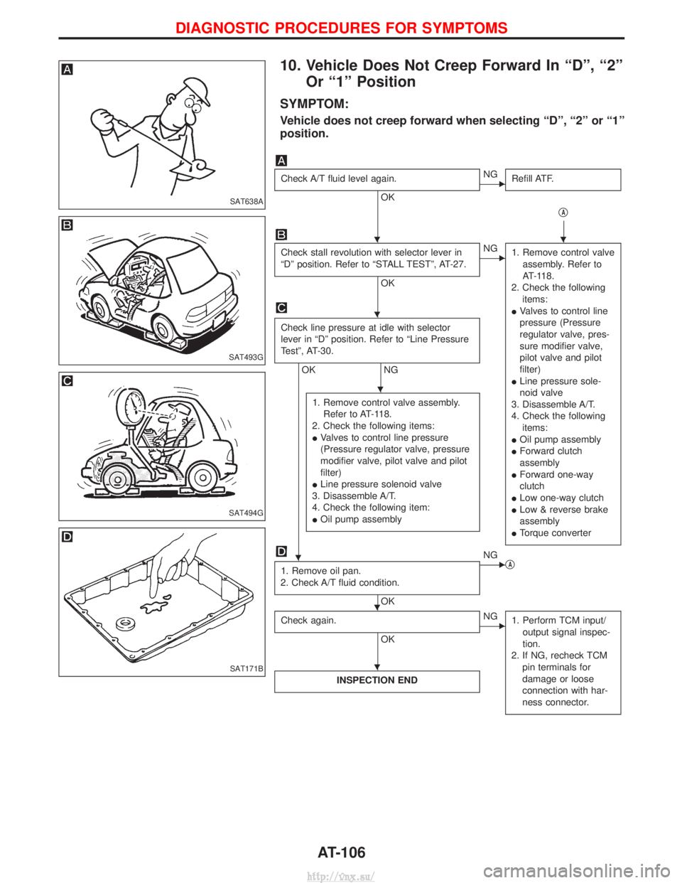
10. Vehicle Does Not Creep Forward In ªDº, ª2ºOr ª1º Position
SYMPTOM:
Vehicle does not creep forward when selecting ªDº, ª2º or ª1º
position.
Check A/T fluid level again.
OK
ENG Refill ATF.
qA
Check stall revolution with selector lever in
ªDº position. Refer to ªSTALL TESTº, AT-27.
OK
ENG1. Remove control valve
assembly. Refer to
AT-118.
2. Check the following items:
I Valves to control line
pressure (Pressure
regulator valve, pres-
sure modifier valve,
pilot valve and pilot
filter)
I Line pressure sole-
noid valve
3. Disassemble A/T.
4. Check the following items:
I Oil pump assembly
I Forward clutch
assembly
I Forward one-way
clutch
I Low one-way clutch
I Low & reverse brake
assembly
I Torque converter
Check line pressure at idle with selector
lever in ªDº position. Refer to ªLine Pressure
Testº, AT-30.
OK NG
1. Remove control valve assembly. Refer to AT-118.
2. Check the following items:
I Valves to control line pressure
(Pressure regulator valve, pressure
modifier valve, pilot valve and pilot
filter)
I Line pressure solenoid valve
3. Disassemble A/T.
4. Check the following item:
I Oil pump assembly
1. Remove oil pan.
2. Check A/T fluid condition.
OK
ENG qA
Check again.
OK
ENG 1. Perform TCM input/
output signal inspec-
tion.
2. If NG, recheck TCM pin terminals for
damage or loose
connection with har-
ness connector.
INSPECTION END
SAT638A
SAT493G
SAT494G
SAT171B
HH
H
H
H
HH
H
DIAGNOSTIC PROCEDURES FOR SYMPTOMS
AT-106
http://vnx.su/
Page 965 of 1833
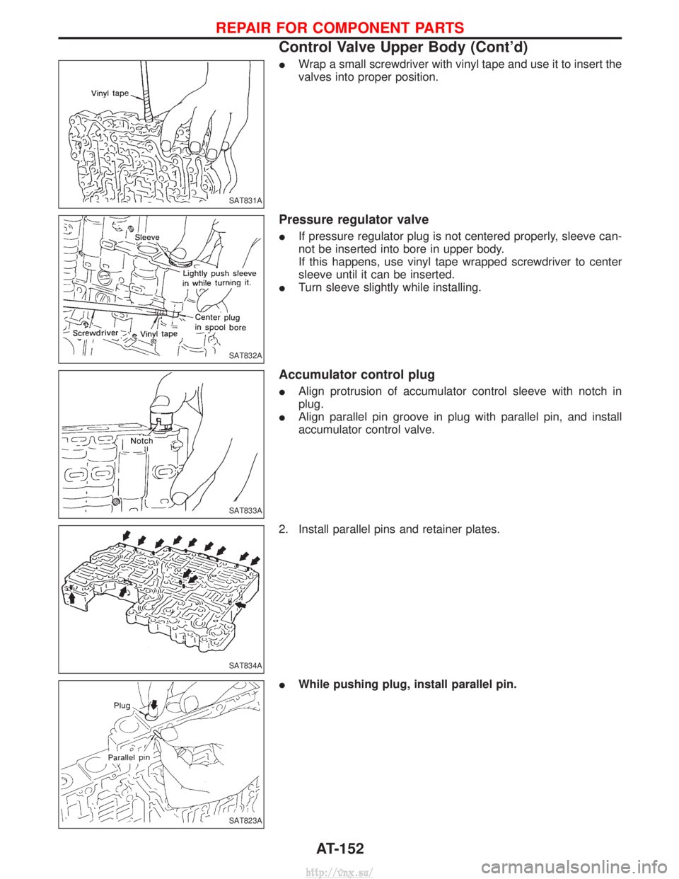
IWrap a small screwdriver with vinyl tape and use it to insert the
valves into proper position.
Pressure regulator valve
IIf pressure regulator plug is not centered properly, sleeve can-
not be inserted into bore in upper body.
If this happens, use vinyl tape wrapped screwdriver to center
sleeve until it can be inserted.
I Turn sleeve slightly while installing.
Accumulator control plug
IAlign protrusion of accumulator control sleeve with notch in
plug.
I Align parallel pin groove in plug with parallel pin, and install
accumulator control valve.
2. Install parallel pins and retainer plates.
I While pushing plug, install parallel pin.
SAT831A
SAT832A
SAT833A
SAT834A
SAT823A
REPAIR FOR COMPONENT PARTS
Control Valve Upper Body (Cont'd)
AT-152
http://vnx.su/