Page 1015 of 1833

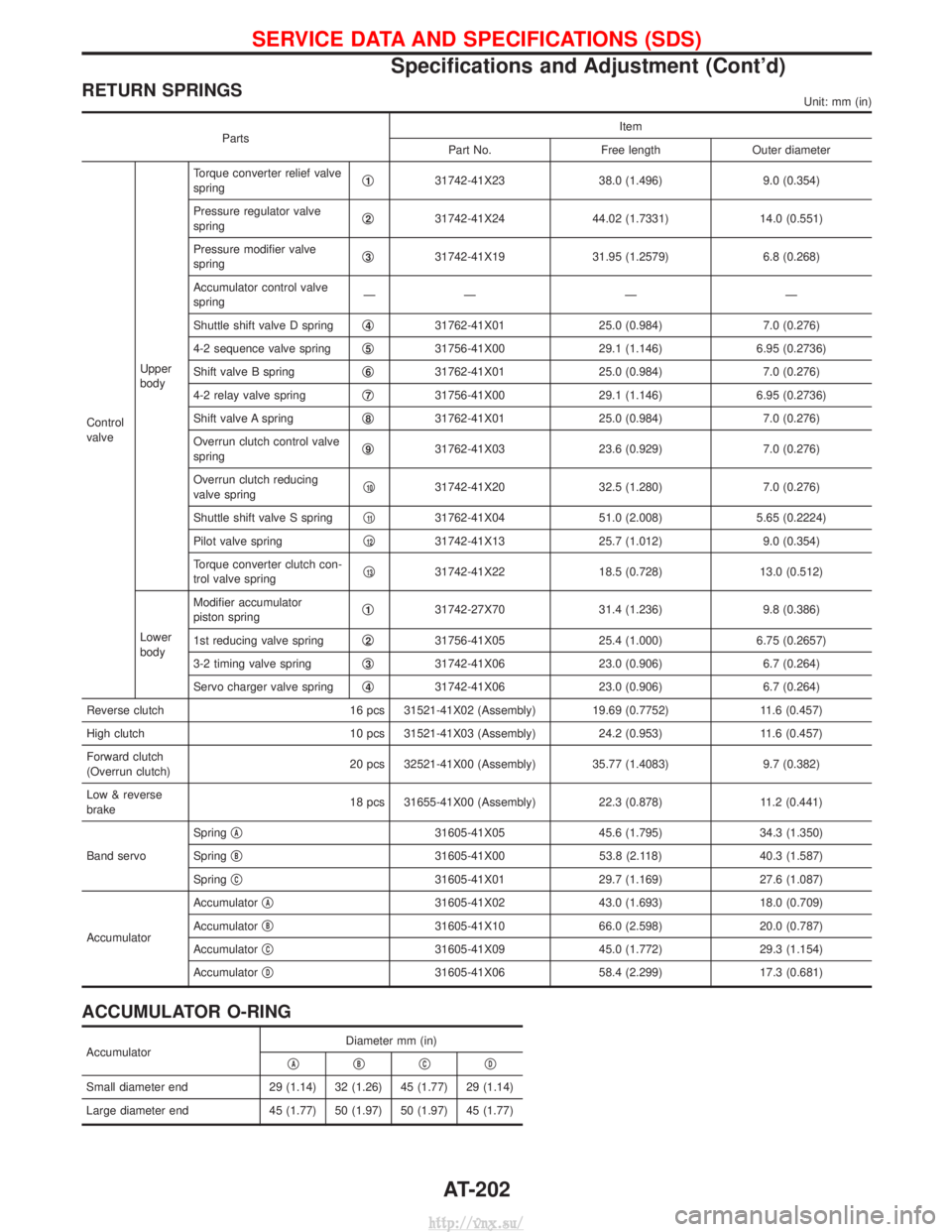
RETURN SPRINGSUnit: mm (in)
PartsItem
Part No. Free length Outer diameter
Control
valve Upper
bodyTorque converter relief valve
spring
q
131742-41X23
38.0 (1.496)9.0 (0.354)
Pressure regulator valve
spring q
231742-41X24
44.02 (1.7331) 14.0 (0.551)
Pressure modifier valve
spring q
331742-41X19
31.95 (1.2579) 6.8 (0.268)
Accumulator control valve
spring ÐÐÐÐ
Shuttle shift valve D spring q
431762-41X01
25.0 (0.984)7.0 (0.276)
4-2 sequence valve spring q
531756-41X00
29.1 (1.146)6.95 (0.2736)
Shift valve B spring q
631762-41X01
25.0 (0.984)7.0 (0.276)
4-2 relay valve spring q
731756-41X00
29.1 (1.146)6.95 (0.2736)
Shift valve A spring q
831762-41X01
25.0 (0.984)7.0 (0.276)
Overrun clutch control valve
spring q
931762-41X03
23.6 (0.929)7.0 (0.276)
Overrun clutch reducing
valve spring q
1031742-41X20
32.5 (1.280)7.0 (0.276)
Shuttle shift valve S spring q
1131762-41X04
51.0 (2.008)5.65 (0.2224)
Pilot valve spring q
1231742-41X13
25.7 (1.012)9.0 (0.354)
Torque converter clutch con-
trol valve spring q
1331742-41X22
18.5 (0.728)13.0 (0.512)
Lower
body Modifier accumulator
piston spring
q
131742-27X70
31.4 (1.236)9.8 (0.386)
1st reducing valve spring q
231756-41X05
25.4 (1.000)6.75 (0.2657)
3-2 timing valve spring q
331742-41X06
23.0 (0.906)6.7 (0.264)
Servo charger valve spring q
431742-41X06
23.0 (0.906)6.7 (0.264)
Reverse clutch 16 pcs 31521-41X02 (Assembly) 19.69 (0.7752) 11.6 (0.457)
High clutch 10 pcs 31521-41X03 (Assembly)24.2 (0.953)11.6 (0.457)
Forward clutch
(Overrun clutch) 20 pcs 32521-41X00 (Assembly) 35.77 (1.4083)
9.7 (0.382)
Low & reverse
brake 18 pcs 31655-41X00 (Assembly)
22.3 (0.878)11.2 (0.441)
Band servo Spring
q
A31605-41X05
45.6 (1.795)34.3 (1.350)
Spring q
B31605-41X00
53.8 (2.118)40.3 (1.587)
Spring q
C31605-41X01
29.7 (1.169)27.6 (1.087)
Accumulator Accumulator
q
A31605-41X02
43.0 (1.693)18.0 (0.709)
Accumulator q
B31605-41X10
66.0 (2.598)20.0 (0.787)
Accumulator q
C31605-41X09
45.0 (1.772)29.3 (1.154)
Accumulator q
D31605-41X06
58.4 (2.299)17.3 (0.681)
ACCUMULATOR O-RING
Accumulator Diameter mm (in)
qAqBqCqD
Small diameter end 29 (1.14) 32 (1.26) 45 (1.77) 29 (1.14)
Large diameter end 45 (1.77) 50 (1.97) 50 (1.97) 45 (1.77)
SERVICE DATA AND SPECIFICATIONS (SDS)
Specifications and Adjustment (Cont'd)
AT-202
http://vnx.su/
Page 1486 of 1833

System Description
The alternator provides DC voltage to operate the vehicle's electrical system and to keep the battery charged.
The voltage output is controlled by the IC regulator.
Power is supplied at all times to alternator terminal 4 (S) (ZD30DDTi engine models) through:
I10A fuse (No. 31, located in the fuse and fusible link box).
Terminal B supplies power to charge the battery and operate the vehicle's electrical system. Output voltage
is controlled by the IC regulator at terminal 4 (S) detecting the input voltage (ZD30DDTi engine models). The
charging circuit is protected by the 100A fusible link.
The alternator is grounded to the engine block.
With the ignition switch in the ON or START position, power is supplied
I through 10A fuse [No. 12, located in the fuse block (J/B)]
I to combination meter terminal 28 for the charge warning lamp.
Ground is supplied to terminal 2 of the combination meter through terminal 1(L) (TD27Ti engine models) or
3(L) (ZD30DDTi engine models) of the alternator. With power and ground supplied, the charge warning lamp
will illuminate. When the alternator is providing sufficient voltage with the engine running, the ground is opened
and the charge warning lamp will go off.
If the charge warning lamp illuminates with the engine running, a malfunction is indicated.
CHARGING SYSTEM
SC-23
http://vnx.su/
Page 1489 of 1833
Trouble Diagnoses
Before conducting an alternator test, make sure that the battery is fully charged. A 30-volt voltmeter and suit-
able test probes are necessary for the test. The alternator can be checked easily by referring to the Inspec-
tion Table.
IBefore starting, inspect the fusible link.
I Use fully charged battery.
WITH IC REGULATOR
NOTE:
IIf the inspection result is OK even though the charging system is malfunctioning, check the B terminal
connection. (Check the tightening torque.)
I When field circuit is open, check condition of rotor coil, rotor slip ring and brush. If necessary, replace faulty
parts with new ones.
MALFUNCTION INDICATOR
The IC regulator warning function activates to illuminate ªCHARGEº warning lamp, if any of the following
symptoms occur while alternator is operating:
IExcessive voltage is produced.
I No voltage is produced.
SEL338V
CHARGING SYSTEM
SC-26
http://vnx.su/
Page 1492 of 1833
STATOR CHECK
1. Continuity test
INo continuity ... Replace stator.
2. Ground test
I Continuity exists ... Replace stator.
Assembly
RING FITTING IN REAR BEARING
IFix ring into groove in rear bearing so that it is as close to the
adjacent area as possible.
CAUTION:
Do not reuse rear bearing after removal.
REAR COVER INSTALLATION
1. Fit brush assembly, diode assembly, regulator assembly and stator.
2. Push brushes up with fingers and install them to rotor.
Take care not to damage slip ring sliding surface.
SEL037Z
SEL044Z
SEL048Z
SEL049Z
CHARGING SYSTEM
Inspection (Cont'd)
SC-29
http://vnx.su/