2004 NISSAN TERRANO sunroof
[x] Cancel search: sunroofPage 1338 of 1833
BODY & TRIM
SECTION
BT
CONTENTS
PRECAUTIONS ...............................................................2
Service Notice..............................................................2
Supplemental Restraint System (SRS) ²AIR
BAG² and²SEAT BELT PRE-TENSIONER² ...............2
CLIP AND FASTENER ....................................................3
Description ...................................................................3
CHASSIS AND BODY MAINTENANCE .........................5
Checking Body Corrosion ............................................5
BODY FRONT END .........................................................6
Removal and Installation .............................................6
BODY REAR END AND OPENER ..................................8
Removal and Installation .............................................8
DOOR ........................................................................\
.....10
Removal and Installation ...........................................10
INSTRUMENT PANEL ASSEMBLY ..............................16
Removal and Installation ...........................................16
SIDE AND FLOOR TRIM ..............................................18
Removal and Installation ...........................................18
DOOR TRIM ...................................................................19
Removal and Installation ...........................................19 ROOF TRIM
...................................................................20
Removal and Installation ...........................................20
EXTERIOR .....................................................................21
Removal and Installation ...........................................21
FRONT SEAT .................................................................34
Removal and Installation ...........................................34
Heated Seat ...............................................................36
Active Head Restraint ................................................36
SECOND SEAT ..............................................................37
Removal and Installation ...........................................37
THIRD SEAT ..................................................................39
Removal and Installation ...........................................39
SUNROOF ......................................................................40
Removal and Installation ...........................................40
WINDSHIELD AND WINDOWS ....................................42
Removal and Installation ...........................................42
DOOR MIRROR .............................................................48
Removal and Installation ...........................................48
BODY (ALIGNMENT) ....................................................49
Alignment ...................................................................49
http://vnx.su/
Page 1342 of 1833
Checking Body Corrosion
Visually check the body sheet metal panel for corrosion, paint damage (scratches, chipping, rubbing, etc.) or
damage to the anti-corrosion materials. In particular, check the following locations.
Hemmed portion
Hood front end, door lower end, back door rear end, etc.
Panel joint
Side sill of rear fender and center pillar, rear wheel housing of rear fender, around strut tower in engine
compartment, etc.
Panel edge
Back door opening, sunroof opening, fender wheelarch flange, fuel filler lid flange, around holes in panel, etc.
Parts contact
Waist molding, windshield molding, bumper, etc.
Protectors
Damage or condition of mudguard, fender protector, chipping protector, etc.
Anti-corrosion materials
Damage or separation of anti-corrosion materials under the body.
Drain holes
Condition of drain holes at door and side sill.
When repairing corroded areas, refer to the Corrosion Repair Manual.
CHASSIS AND BODY MAINTENANCE
BT-5
http://vnx.su/
Page 1377 of 1833
Removal and Installation
IAfter any adjustment, check sunroof operation and lid alignment.
I Handle finisher plate and glass lid with care so not to cause damage.
I It is desirable for easy installation to mark each point before removal.
CAUTION:
I Always work with a helper.
I Remove sunroof frame rear door opening.
SUNROOF LID ASSEMBLY
q1Open sunroof shade.
q
2Close sunroof lid, and remove adjustment screw covers.
q
3Remove the four adjuster screws
q
4Remove sunroof lid assembly.
SUNROOF ASSEMBLY
1. Remove headlining. For details, refer to ªROOF TRIMº, BT-20.
2. Disconnect interior lamp harness.
3. Disconnect front and rear drain hoses.
4. Remove nuts and bolts securing sunroof frame and motor to roof.
5. Remove sunroof assembly.
SUNROOF
BT-40
http://vnx.su/
Page 1378 of 1833

YBT127
SUNROOF
Removal and Installation (Cont'd)BT-41
http://vnx.su/
Page 1495 of 1833
Oil Pressure Switch Check ...................................... 110
Wiring Diagram - CHIME - ...................................... 111
WIPER AND WASHER ................................................ 112
Wiring Diagram - WIPER - ...................................... 112
Wiring Diagram - WIP/R -........................................ 114
Installation ................................................................ 116
Washer Nozzle Adjustment ..................................... 117
Check Valve ............................................................. 117
Wiring Diagram - HLC - ........................................... 118
HORN, CIGARETTE LIGHTER AND CLOCK ............122
Wiring Diagram - HORN - .......................................122
Wiring Diagram - CIGAR -.......................................123
Wiring Diagram - CLOCK -......................................124
REAR WINDOW DEFOGGER AND DOOR
MIRROR DEFOGGER .................................................125
System Description ..................................................125
Wiring Diagram - DEF - ...........................................126
Trouble Diagnoses...................................................128
Filament Check ........................................................132
Filament Repair .......................................................133
AUDIO ........................................................................\
..134
System Description ..................................................134
Schematic ................................................................136
Wiring Diagram - AUDIO - .......................................138
Wiring Diagram - REMOTE -...................................145
Trouble Diagnoses...................................................147
Inspection.................................................................149
Location of Roof Mounted Antenna .........................150
HEATED SEAT ............................................................151
Wiring Diagram - HSEAT - ......................................151
SUNROOF ....................................................................153
Wiring Diagram - SROOF - .....................................153
DOOR MIRROR ...........................................................154
Wiring Diagram - MIRROR - ...................................154
POWER WINDOW .......................................................156
System Description ..................................................156
Schematic ................................................................158
Wiring Diagram - WINDOW - ..................................159
Trouble Diagnoses...................................................162
POWER DOOR LOCK .................................................163
System Description ..................................................163
Schematic ................................................................164
Wiring Diagram - D/LOCK -.....................................166
Trouble Diagnoses...................................................171
POWER DOOR LOCK - SUPER LOCK - ...................179
Component Parts Location ......................................179
System Description ..................................................180
Schematic ................................................................182 Wiring Diagram - S/LOCK - .....................................184
Trouble Diagnoses...................................................192
MULTI-REMOTE CONTROL SYSTEM .......................202
System Description ..................................................202
Schematic ................................................................204
Wiring Diagram - MULTI - .......................................205
Trouble Diagnoses...................................................213
ID Code Entry Procedure ........................................215
TIME CONTROL UNIT (TCU) .....................................216
System Description ..................................................216
Trouble Diagnosis ....................................................218
Schematic ................................................................220
NATS (Nissan Anti-Theft System) .............................222
System Description ..................................................222
System Composition ................................................223
Component Parts Location ......................................224
Wiring Diagram - NATS -.........................................225
CONSULT-II .............................................................229
Trouble Diagnoses...................................................231
How to Replace NATS IMMU ..................................242
THEFT WARNING SYSTEM .......................................243
Components Parts and Harness Connector
Location ...................................................................243
System Description ..................................................244
Theft Warning System/Schematic ...........................247
Wiring Diagram - THEFT -.......................................248
Trouble Diagnoses...................................................264
LOCATION OF ELECTRICAL UNITS .........................275
Engine Compartment ...............................................275
Passenger Compartment/LHD Models ....................276
Passenger Compartment/RHD Models ...................278
HARNESS LAYOUT ....................................................280
How to Read Harness Layout .................................280
Outline......................................................................281
Main Harness...........................................................282
EFC Harness ...........................................................298
Engine Harness .......................................................310
Body Harness ..........................................................312
Chassis Harness......................................................320
Room Lamp Harness...............................................321
Tailgate Harness ......................................................322
Door Harness (LH side)...........................................323
Door Harness (RH side) ..........................................324
BULB SPECIFICATIONS ............................................325
Headlamps ...............................................................325
Exterior Lamps.........................................................325
Interior Lamps ..........................................................325
WIRING DIAGRAM CODES (CELL CODES) .............326
CONTENTS(Cont'd)
EL-2
http://vnx.su/
Page 1565 of 1833
![NISSAN TERRANO 2004 Service Repair Manual System Description
POWER SUPPLY AND GROUND
Power is supplied at all times:
Ithrough 15A fuse [No. 5, located in the fuse block (J/B)]
I to time control unit terminal U09,
I through 10A fuse [No. 16, l NISSAN TERRANO 2004 Service Repair Manual System Description
POWER SUPPLY AND GROUND
Power is supplied at all times:
Ithrough 15A fuse [No. 5, located in the fuse block (J/B)]
I to time control unit terminal U09,
I through 10A fuse [No. 16, l](/manual-img/5/57394/w960_57394-1564.png)
System Description
POWER SUPPLY AND GROUND
Power is supplied at all times:
Ithrough 15A fuse [No. 5, located in the fuse block (J/B)]
I to time control unit terminal U09,
I through 10A fuse [No. 16, located in the fuse block (J/B)]
I to front interior lamp terminal 1,
I to rear interior lamp terminal 1 (Wagon models)
I to rear room lamp terminal 2 (Hardtop models)
I to sunroof switch and map lamps terminal 3 (with sunroof),
I to map lamp terminal 2 (without sunroof).
Ground is supplied:
I through body grounds terminals F36, F47 (LHD models) or M33, M754 (RHD models).
I through fuse block terminal MM2
I to time control unit terminal U16
When the driver side door is opened, ground is supplied:
I through driver side door switch case ground and terminal 1, and
I through fuse block terminal B07
I to time control unit terminal U06
When any door is opened, ground is supplied:
I through case ground and terminal 1 of each door switch,
I through fuse block terminal B01
I to time control unit terminal U07.
When the driver side door is unlocked by the door lock/unlock switch, the time control unit receives a ground
signal:
I through body grounds B10 and B18
I to power window main switch terminal 3
I from power window main switch terminal 7
I to time control unit terminal U37.
When a signal, or combination of signals is received by the time control unit, ground is supplied:
I through time control unit terminal U12 and fuse block terminal R01
I to front interior room lamp terminal 2.
I to rear interior lamp terminal 2 (Wagon models).
I to rear interior room lamp terminal 1 (Hardtop models).
With power and ground supplied, the interior room lamps illuminate when the lamp switch is in ªDOORº posi-
tion.
SWITCH OPERATION
When interior room lamp switch is in ªONº position, ground is supplied:
I through front interior lamp case ground.
I through rear interior lamp case ground (Wagon models).
When sunroof switch and map lamps (with sunroof) is ON, ground is supplied:
I through body grounds F36, F47 (LHD models) or M33, M754 (RHD models)
I through fuse block terminal MM2 and R03
I to sunroof switch map lamps terminal 2.
When map lamp (without sunroof) is ON, ground is supplied:
I through body grounds F36, F47 (LHD models) or M33, M754 (RHD models)
I through fuse block terminal MM2 and R03
I to map lamp terminal 1.
With power and ground supplied, the interior room lamps, map lamps illuminate.
INTERIOR ROOM LAMP TIMER OPERATION
When interior room lamp switch is in the ªDOORº position, the time control unit keeps the interior room lamp
illuminated for about 30 seconds when:
I unlock signal is supplied from door lock/unlock switch while all doors are closed
I unlock signal is supplied from remote controller or door key cylinder while all doors are closed
I driver's door is opened and then closed
The timer is canceled when:
I driver's door is locked,
INTERIOR LAMP
EL-72
http://vnx.su/
Page 1646 of 1833
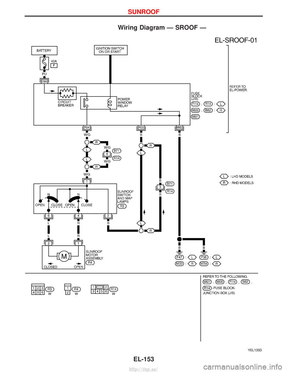
Wiring Diagram Ð SROOF Ð
YEL135D
SUNROOF
EL-153
http://vnx.su/
Page 1819 of 1833
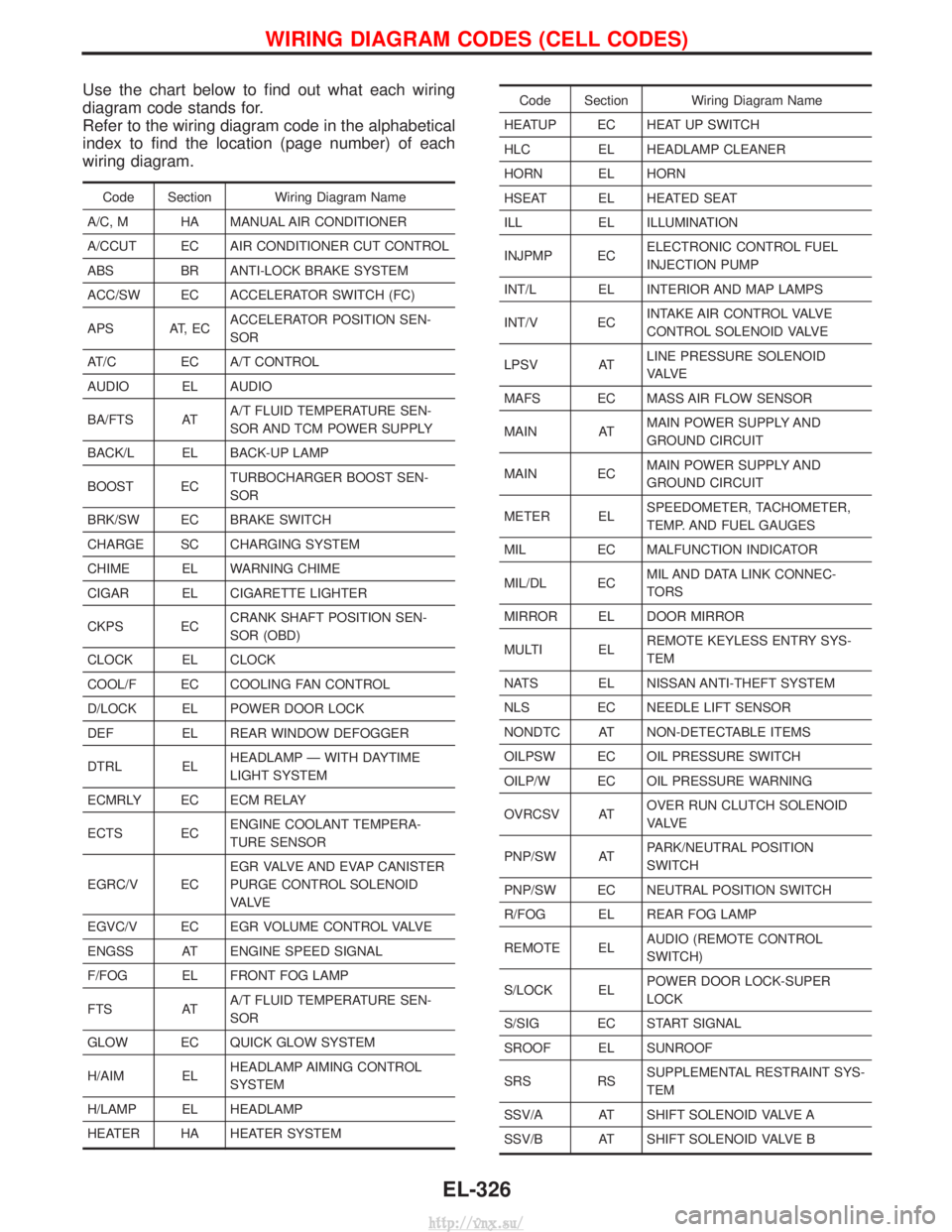
Use the chart below to find out what each wiring
diagram code stands for.
Refer to the wiring diagram code in the alphabetical
index to find the location (page number) of each
wiring diagram.
Code Section Wiring Diagram Name
A/C, M HA MANUAL AIR CONDITIONER
A/CCUT EC AIR CONDITIONER CUT CONTROL
ABS BR ANTI-LOCK BRAKE SYSTEM
ACC/SW EC ACCELERATOR SWITCH (FC)
APS AT, EC ACCELERATOR POSITION SEN-
SOR
AT/C EC A/T CONTROL
AUDIO EL AUDIO
BA/FTS AT A/T FLUID TEMPERATURE SEN-
SOR AND TCM POWER SUPPLY
BACK/L EL BACK-UP LAMP
BOOST EC TURBOCHARGER BOOST SEN-
SOR
BRK/SW EC BRAKE SWITCH
CHARGE SC CHARGING SYSTEM
CHIME EL WARNING CHIME
CIGAR EL CIGARETTE LIGHTER
CKPS EC CRANK SHAFT POSITION SEN-
SOR (OBD)
CLOCK EL CLOCK
COOL/F EC COOLING FAN CONTROL
D/LOCK EL POWER DOOR LOCK
DEF EL REAR WINDOW DEFOGGER
DTRL EL HEADLAMP Ð WITH DAYTIME
LIGHT SYSTEM
ECMRLY EC ECM RELAY
ECTS EC ENGINE COOLANT TEMPERA-
TURE SENSOR
EGRC/V EC EGR VALVE AND EVAP CANISTER
PURGE CONTROL SOLENOID
VA LV E
EGVC/V EC EGR VOLUME CONTROL VALVE
ENGSS AT ENGINE SPEED SIGNAL
F/FOG EL FRONT FOG LAMP
FTS AT A/T FLUID TEMPERATURE SEN-
SOR
GLOW EC QUICK GLOW SYSTEM
H/AIM EL HEADLAMP AIMING CONTROL
SYSTEM
H/LAMP EL HEADLAMP
HEATER HA HEATER SYSTEM
Code Section Wiring Diagram Name
HEATUP EC HEAT UP SWITCH
HLC EL HEADLAMP CLEANER
HORN EL HORN
HSEAT EL HEATED SEAT
ILL EL ILLUMINATION
INJPMP EC ELECTRONIC CONTROL FUEL
INJECTION PUMP
INT/L EL INTERIOR AND MAP LAMPS
INT/V EC INTAKE AIR CONTROL VALVE
CONTROL SOLENOID VALVE
LPSV AT LINE PRESSURE SOLENOID
VA LV E
MAFS EC MASS AIR FLOW SENSOR
MAIN AT MAIN POWER SUPPLY AND
GROUND CIRCUIT
MAIN EC MAIN POWER SUPPLY AND
GROUND CIRCUIT
METER EL SPEEDOMETER, TACHOMETER,
TEMP. AND FUEL GAUGES
MIL EC MALFUNCTION INDICATOR
MIL/DL EC MIL AND DATA LINK CONNEC-
TORS
MIRROR EL DOOR MIRROR
MULTI EL REMOTE KEYLESS ENTRY SYS-
TEM
NATS EL NISSAN ANTI-THEFT SYSTEM
NLS EC NEEDLE LIFT SENSOR
NONDTC AT NON-DETECTABLE ITEMS
OILPSW EC OIL PRESSURE SWITCH
OILP/W EC OIL PRESSURE WARNING
OVRCSV AT OVER RUN CLUTCH SOLENOID
VA LV E
PNP/SW AT PARK/NEUTRAL POSITION
SWITCH
PNP/SW EC NEUTRAL POSITION SWITCH
R/FOG EL REAR FOG LAMP
REMOTE EL AUDIO (REMOTE CONTROL
SWITCH)
S/LOCK EL POWER DOOR LOCK-SUPER
LOCK
S/SIG EC START SIGNAL
SROOF EL SUNROOF
SRS RS SUPPLEMENTAL RESTRAINT SYS-
TEM
SSV/A AT SHIFT SOLENOID VALVE A
SSV/B AT SHIFT SOLENOID VALVE B
WIRING DIAGRAM CODES (CELL CODES)
EL-326
http://vnx.su/