2004 NISSAN TERRANO gas type
[x] Cancel search: gas typePage 9 of 1833
Precautions for Fuel
DIESEL ENGINE*:
Diesel fuel of at least 50 cetane for ZD30DDTi engine.
* If two types of diesel fuel are available, use summer or winterfuel properly according to the following temperature conditions.
I Above þ7ÉC (20ÉF) ... Summer type diesel fuel.
I Below þ7ÉC (20ÉF) ... Winter type diesel fuel.
CAUTION:
I Do not use home heating oil, gasoline, or other alternate
fuels in your diesel engine. The use of those can cause
engine damage.
I Do not use summer fuel at temperature below þ7ÉC (20ÉF).
The cold temperature will cause wax to form in the fuel. As
a result, it may prevent the engine from running smoothly.
I Do not add gasoline or other alternate fuels to diesel fuel.
Precautions for Engine Oils
Prolonged and repeated contact with mineral oil will result in the
removal of natural fats from the skin, leading to dryness, irritation
and dermatitis. In addition, used engine oil contains potentially
harmful contaminants which may cause skin cancer. Adequate
means of skin protection and washing facilities must be provided.
HEALTH PROTECTION PRECAUTIONS
1. Avoid prolonged and repeated contact with oils, particularly
used engine oils.
2. Wear protective clothing, including impervious gloves where practicable.
3. Do not put oily rags in pockets.
4. Avoid contaminating clothes, particularly underwear, with oil.
5. Heavily soiled clothing and oil-impregnated footwear should not be worn. Overalls must be cleaned regularly.
6. First Aid treatment should be obtained immediately for open cuts and wounds.
7. Use barrier creams, applying them before each work period, to help the removal of oil from the skin.
8. Wash with soap and water to ensure all oil is removed (skin cleansers and nail brushes will help). Preparations containing
lanolin replace the natural skin oils which have been removed.
9. Do not use petrol, kerosine, diesel fuel, gas oil, thinners or sol- vents for cleaning skin.
10. If skin disorders develop, obtain medical advice without delay.
11. Where practicable, degrease components prior to handling.
12. Where there is a risk of eye contact, eye protection should be worn, for example, chemical goggles or face shields; in addition
an eye wash facility should be provided.
(For the United Kingdom, see also HSE Cautionary Notice SHW
397 ªEffects of Mineral Oil on the Skinº.)
ENVIRONMENTAL PROTECTION PRECAUTIONS
Burning used engine oil in small space heaters or boilers can be
recommended only for units of approved design. The heating sys-
tem must meet the requirements of HM Inspectorate of Pollution for
small burners of less than 0.4 MW. If in doubt check with the
appropriate local authority and/or manufacturer of the approved
appliance.
PRECAUTIONS
GI-6
http://vnx.su/
Page 817 of 1833
Supplemental Restraint System (SRS) ªAIR
BAGº and ªSEAT BELT PRE-TENSIONERº
The Supplemental Restraint System such as ªAIR BAGº and ªSEAT BELT PRE-TENSIONERº used along with
a seat belt, helps to reduce the risk or severity of injury to the driver and front passenger for certain types of
collision. The SRS composition which is available to NISSAN MODEL R20 is as follows (The composition
varies according to the destination and optional equipment.):
IFor a frontal collision
The Supplemental Restraint System consists of driver air bag module (located in the center of the steer-
ing wheel), front passenger air bag module (located on the instrument panel on passenger side), front seat
belt pre-tensioners, a diagnosis sensor unit, warning lamp, wiring harness and spiral cable.
I For a side collision
The Supplemental Restraint System consists of front side air bag module (located in the outer side of front
seat), side air bag (satellite) sensor, diagnosis sensor unit (one of components of air bags for a frontal
collision), wiring harness, warning lamp (one of components of air bags for a frontal collision).
WARNING:
I To avoid rendering the SRS inoperative, which could increase the risk of personal injury or death
in the event of a collision which would result in air bag inflation, all maintenance should be per-
formed by an authorized NISSAN dealer.
I Improper maintenance, including incorrect removal and installation of the SRS, can lead to per-
sonal injury caused by unintentional activation of the system.
I Do not use electrical test equipment on any circuit related to the SRS unless instructed to in this
Service Manual. Spiral cable and wiring harnesses covered with yellow insulation tape either just
before the harness connectors or for the complete harness are related to the SRS.
Precautions for SRS ªAIR BAGº and ªSEAT
BELT PRE-TENSIONERº Service
IDo not use electrical test equipment to check SRS circuits unless instructed to in this Service Manual.
I Before servicing the SRS, turn ignition switch ªOFFº, disconnect both battery cables and wait at least 3
minutes.
For approximately 3 minutes after the cables are removed, it is still possible for the air bag and seat belt
pre-tensioner to deploy. Therefore, do not work on any SRS connectors or wires until at least 3 minutes
have passed.
I Diagnosis sensor unit must always be installed with their arrow marks ª +º pointing towards the front of
the vehicle for proper operation. Also check diagnosis sensor unit for cracks, deformities or rust before
installation and replace as required.
I The spiral cable must be aligned with the neutral position since its rotations are limited. Do not attempt to
turn steering wheel or column after removal of steering gear.
I Handle air bag module carefully. Always place driver and front passenger air bag modules with the pad
side facing upward and place front side air bag module (built-in type) standing with stud bolt side setting
bottom.
I Conduct self-diagnosis to check entire SRS for proper function after replacing any components.
I After air bag inflates, the front instrument panel assembly should be replaced if damaged.
Precautions
IBefore proceeding with disassembly, thoroughly clean the outside of the transmission. It is important to
prevent the internal parts from becoming contaminated by dirt or other foreign matter.
I Disassembly should be done in a clean work area.
I Use lint-free cloth or towels for wiping parts clean. Common shop rags can leave fibers that could inter-
fere with the operation of the transmission.
I Place disassembled parts in order for easier and proper assembly.
I All parts should be carefully cleaned with a general purpose, non-flammable solvent before inspection or
reassembly.
I Gaskets, seals and O-rings should be replaced any time the transmission is disassembled.
I It is very important to perform functional tests whenever they are indicated.
I The valve body contains precision parts and requires extreme care when parts are removed and serviced.
Place removed parts in a parts rack in order to replace them in correct positions and sequences. Care will
also prevent springs and small parts from becoming scattered or lost.
I Properly installed valves, sleeves, plugs, etc. will slide along bores in valve body under their own weight.
PREPARATION AND PRECAUTIONS
AT- 4
http://vnx.su/
Page 1255 of 1833
Supplemental Restraint System (SRS) ªAIR
BAGº and ªSEAT BELT PRE-TENSIONERº
The Supplemental Restraint System such as ªAIR BAGº and ªSEAT BELT PRE-TENSIONERº used along with
a seat belt, helps to reduce the risk or severity of injury to the driver and front passenger for certain types of
collision. The SRS composition which is available to NISSAN MODEL R20 is as follows (The composition
varies according to the destination and optional equipment.):
IFor a frontal collision
The Supplemental Restraint System consists of driver air bag module (located in the center of the steer-
ing wheel), front passenger air bag module (located on the instrument panel on passenger side), front seat
belt pre-tensioners, a diagnosis sensor unit, warning lamp, wiring harness and spiral cable.
I For a side collision
The Supplemental Restraint System consists of front side air bag module (located in the outer side of front
seat), side air bag (satellite) sensor, diagnosis sensor unit (one of components of air bags for a frontal
collision), wiring harness, warning lamp (one of components of air bags for a frontal collision).
WARNING:
I To avoid rendering the SRS inoperative, which could increase the risk of personal injury or death
in the event of a collision which would result in air bag inflation, all maintenance should be per-
formed by an authorized NISSAN dealer.
I Improper maintenance, including incorrect removal and installation of the SRS, can lead to per-
sonal injury caused by unintentional activation of the system.
I Do not use electrical test equipment on any circuit related to the SRS unless instructed to in this
Service Manual. Spiral cable and wiring harnesses covered with yellow insulation tape either just
before the harness connectors or for the complete harness are related to the SRS.
Precautions for SRS ªAIR BAGº and ªSEAT
BELT PRE-TENSIONERº Service
IDo not use electrical test equipment to check SRS circuits unless instructed to in this Service Manual.
I Before servicing the SRS, turn ignition switch ªOFFº, disconnect both battery cables and wait at least 3
minutes.
For approximately 3 minutes after the cables are removed, it is still possible for the air bag and seat belt
pre-tensioner to deploy. Therefore, do not work on any SRS connectors or wires until at least 3 minutes
have passed.
I Diagnosis sensor unit must always be installed with their arrow marks ª +º pointing towards the front of
the vehicle for proper operation. Also check diagnosis sensor unit for cracks, deformities or rust before
installation and replace as required.
I The spiral cable must be aligned with the neutral position since its rotations are limited. Do not attempt to
turn steering wheel or column after removal of steering gear.
I Handle air bag module carefully. Always place driver and front passenger air bag modules with the pad
side facing upward and place front side air bag module (built-in type) standing with stud bolt side setting
bottom.
I Conduct self-diagnosis to check entire SRS for proper function after replacing any components.
I After air bag inflates, the front instrument panel assembly should be replaced if damaged.
Precautions for Steering System
IBefore disassembly, thoroughly clean the outside of the unit.
I Disassembly should be done in a clean work area. It is important to prevent the internal parts from
becoming contaminated by dirt or other foreign matter.
I When disassembling parts, be sure to place them in order on a part rack so they can be reinstalled
in their proper positions.
I Use nylon cloths or paper towels to clean the parts; common shop rags can leave lint that might
interfere with their operation.
I Before inspection or reassembly, carefully clean all parts with a general purpose, non-flammable
solvent.
I Before assembly, apply a coat of recommended ATF* to hydraulic parts. Vaseline may be applied
to O-rings and seals. Do not use any grease.
I Replace all gaskets, seals and O-rings. Avoid damaging O-rings, seals and gaskets during instal-
lation. Perform functional tests whenever designated.
*: Automatic transmission fluid
PRECAUTIONS
ST-2
http://vnx.su/
Page 1401 of 1833
Precautions for Working with HFC-134a
(R-134a)
WARNING:I CFC-12 (R-12) refrigerant and HFC-134a (R-134a) refrigerant must never be mixed, even in the
smallest amounts, as they are incompatible with each other. If the refrigerants are mixed, com-
pressor failure is likely to occur.
I Use only specified lubrication oil for the HFC-134a (R-134a) A/C system and HFC-134a (R-134a)
components. If lubrication oil other than that specified is used, compressor failure is likely to
occur.
I The specified HFC-134a (R-134a) lubrication oil absorbs moisture from the atmosphere at a rapid
rate, therefore the following handling precautions must be observed:
a: When removing refrigerant components from a vehicle, immediately cap (seal) the component to minimize the entry of moisture from the atmosphere.
b: When installing refrigerant components to a vehicle, do not remove the caps (unseal) until just before connecting the components. Also, complete the connection of all refrigerant loop
components as quickly as possible to minimize the entry of moisture into the system.
c: Use the specified lubrication oil from a sealed container only. Containers must be re-sealed immediately after dispensing the lubrication oil. Lubrication oil in containers which are not
properly sealed will become moisture saturated, and such lubrication oil is no longer suitable
for use and should be properly disposed of.
d: Avoid breathing A/C refrigerant and lubricant vapor or mist. Exposure may irritate eyes, nose and throat. Use only approved recovery/recycling equipment to discharge HFC-134a (R-134a)
system. If accidental system discharge occurs, ventilate work area before resuming service.
Additional health and safety information may be obtained from refrigerant and lubricant
manufacturers.
e: Do not allow lubrication oil (Nissan A/C System Oil Type S or Type R) to come in contact with styrofoam parts. Damage may result.
General Refrigerant Precautions
WARNING:
I Do not release refrigerant into the air. Use approved recovery/recycling equipment to capture the
refrigerant every time an air conditioning system is discharged.
I Always wear eye and hand protection (goggles and gloves) when working with any refrigerant or
air conditioning system.
I Do not store or heat refrigerant containers above 52ÉC (125ÉF).
I Do not heat a refrigerant container with an open flame; if container warming is required, place the
bottom of the container in a warm pail of water.
I Do not drop, puncture, or incinerate refrigerant containers.
I Keep refrigerant away from open flames: poisonous gas will be produced if refrigerant burns.
I Refrigerant will displace oxygen, therefore be certain to work in well ventilated areas to prevent
suffocation.
I Do not introduce compressed air to any refrigerant container or refrigerant component.
PRECAUTIONS
HA-4
http://vnx.su/
Page 1402 of 1833
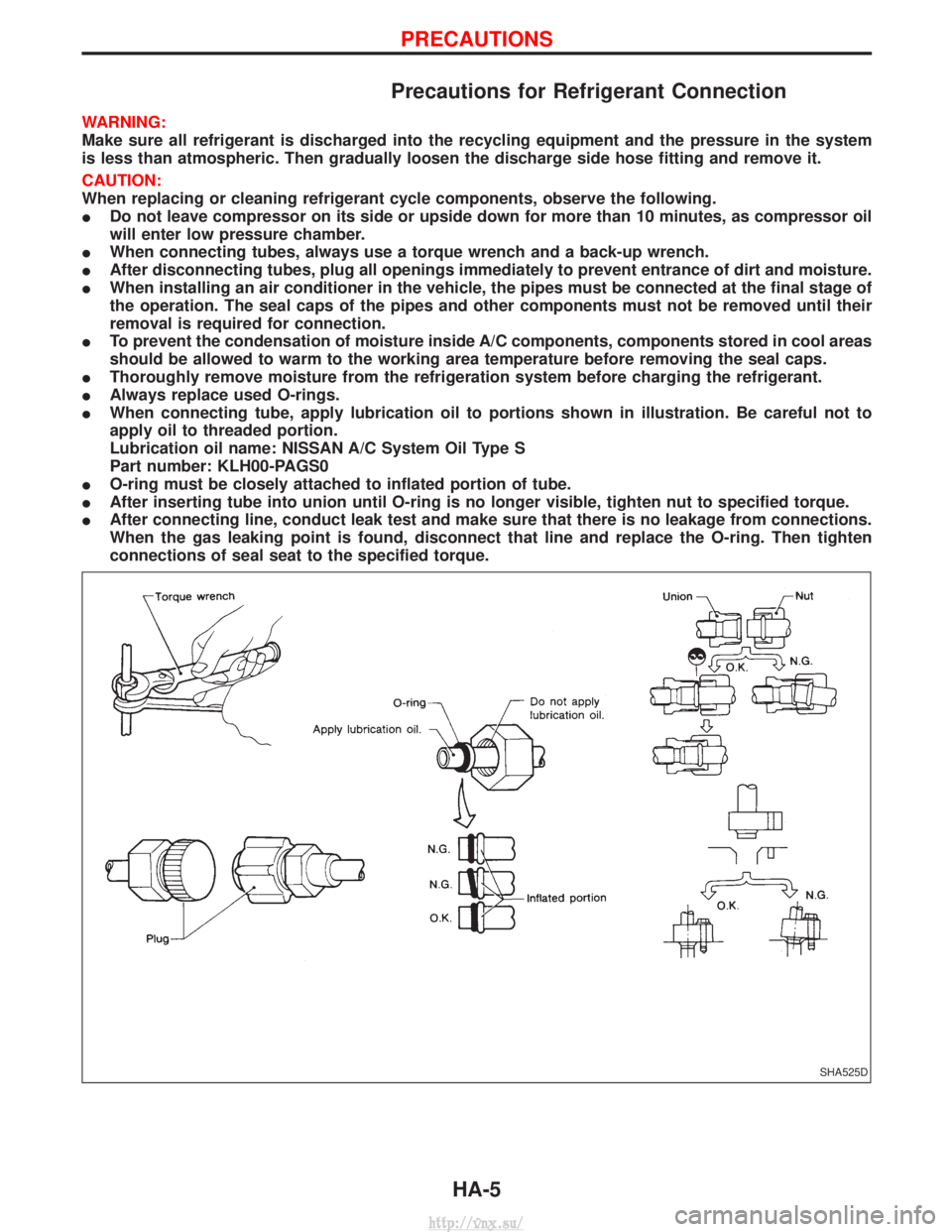
Precautions for Refrigerant Connection
WARNING:
Make sure all refrigerant is discharged into the recycling equipment and the pressure in the system
is less than atmospheric. Then gradually loosen the discharge side hose fitting and remove it.
CAUTION:
When replacing or cleaning refrigerant cycle components, observe the following.
IDo not leave compressor on its side or upside down for more than 10 minutes, as compressor oil
will enter low pressure chamber.
I When connecting tubes, always use a torque wrench and a back-up wrench.
I After disconnecting tubes, plug all openings immediately to prevent entrance of dirt and moisture.
I When installing an air conditioner in the vehicle, the pipes must be connected at the final stage of
the operation. The seal caps of the pipes and other components must not be removed until their
removal is required for connection.
I To prevent the condensation of moisture inside A/C components, components stored in cool areas
should be allowed to warm to the working area temperature before removing the seal caps.
I Thoroughly remove moisture from the refrigeration system before charging the refrigerant.
I Always replace used O-rings.
I When connecting tube, apply lubrication oil to portions shown in illustration. Be careful not to
apply oil to threaded portion.
Lubrication oil name: NISSAN A/C System Oil Type S
Part number: KLH00-PAGS0
I O-ring must be closely attached to inflated portion of tube.
I After inserting tube into union until O-ring is no longer visible, tighten nut to specified torque.
I After connecting line, conduct leak test and make sure that there is no leakage from connections.
When the gas leaking point is found, disconnect that line and replace the O-ring. Then tighten
connections of seal seat to the specified torque.
SHA525D
PRECAUTIONS
HA-5
http://vnx.su/
Page 1420 of 1833
Lubrication Oil
Name: Nissan A/C System Oil Type S
Part number: KLH00-PAGS0
Maintenance of Oil Quantity in Compressor
The oil used to lubricate the compressor circulates through the
system with the refrigerant. Whenever any component of the sys-
tem is replaced or a large amount of gas leakage occurs, add oil
to the compressor to maintain the specified amount.
If oil quantity is not maintained properly, the following malfunctions
may result:
ILack of oil: May lead to a seized compressor
I Excessive oil: Inadequate cooling (thermal exchange impeded)
Checking and Adjusting
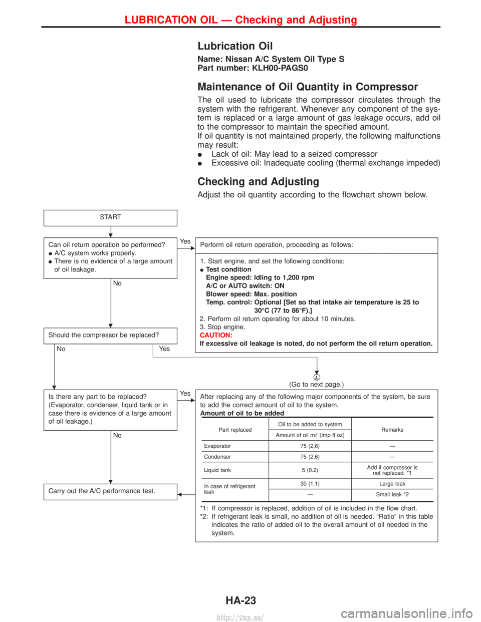
Adjust the oil quantity according to the flowchart shown below.
START
Can oil return operation be performed?
IA/C system works properly.
I There is no evidence of a large amount
of oil leakage.
No
EYe s
Perform oil return operation, proceeding as follows:
------------------------------------------------------------------------------------------------------------------------------------------------------------------------------------------------------------------------------------------------------------------------------------------------------------------------------------------------------------------------------------------------------------------------------------------------------------------------------------------------------------------------------------------------------------- 1. Start engine, and set the following conditions:
I Test condition
Engine speed: Idling to 1,200 rpm
A/C or AUTO switch: ON
Blower speed: Max. position
Temp. control: Optional [Set so that intake air temperature is 25 to
30ÉC (77 to 86ÉF).]
2. Perform oil return operating for about 10 minutes.
3. Stop engine.
CAUTION:
If excessive oil leakage is noted, do not perform the oil return operation.
Should the compressor be replaced?
No Yes
qA(Go to next page.)
Is there any part to be replaced?
(Evaporator, condenser, liquid tank or in
case there is evidence of a large amount
of oil leakage.)
No
EYe s After replacing any of the following major components of the system, be sure
to add the correct amount of oil to the system.
Amount of oil to be added
*1: If compressor is replaced, addition of oil is included in the flow chart.
*2: If refrigerant leak is small, no addition of oil is needed. ªRatioº in this table indicates the ratio of added oil to the overall amount of oil needed in the
system.
Carry out the A/C performance test.F
Part replaced Oil to be added to system
Remarks
Amount of oil m (Imp fl oz)
Evaporator 75 (2.6)Ð
Condenser 75 (2.6)Ð
Liquid tank 5 (0.2)Add if compressor is
not replaced. *1
In case of refrigerant
leak 30 (1.1)
Large leak
Ð Small leak *2
H
H
H
H
H
LUBRICATION OIL Ð Checking and Adjusting
HA-23
http://vnx.su/