Page 159 of 1833

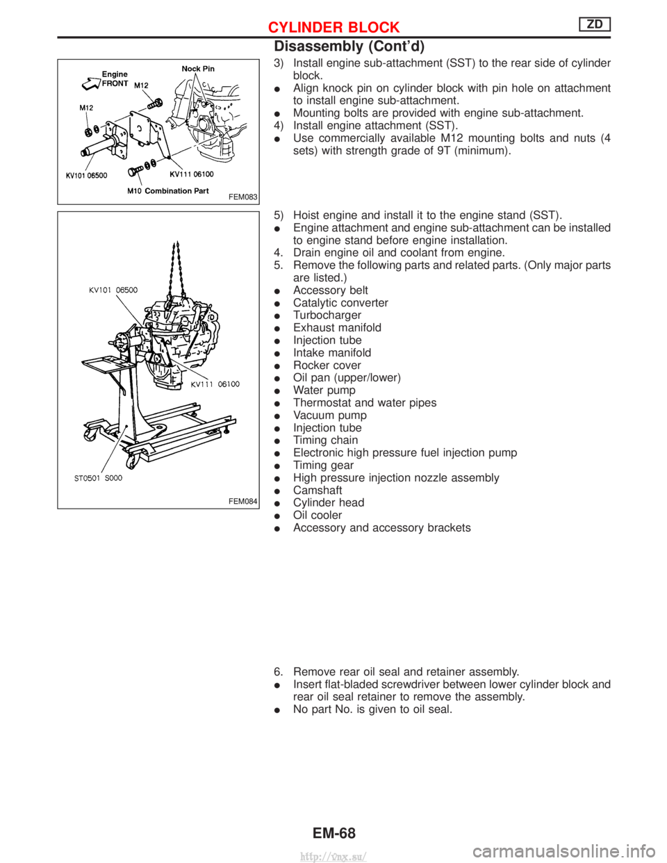
3) Install engine sub-attachment (SST) to the rear side of cylinderblock.
I Align knock pin on cylinder block with pin hole on attachment
to install engine sub-attachment.
I Mounting bolts are provided with engine sub-attachment.
4) Install engine attachment (SST).
I Use commercially available M12 mounting bolts and nuts (4
sets) with strength grade of 9T (minimum).
5) Hoist engine and install it to the engine stand (SST).
I Engine attachment and engine sub-attachment can be installed
to engine stand before engine installation.
4. Drain engine oil and coolant from engine.
5. Remove the following parts and related parts. (Only major parts are listed.)
I Accessory belt
I Catalytic converter
I Turbocharger
I Exhaust manifold
I Injection tube
I Intake manifold
I Rocker cover
I Oil pan (upper/lower)
I Water pump
I Thermostat and water pipes
I Vacuum pump
I Injection tube
I Timing chain
I Electronic high pressure fuel injection pump
I Timing gear
I High pressure injection nozzle assembly
I Camshaft
I Cylinder head
I Oil cooler
I Accessory and accessory brackets
6. Remove rear oil seal and retainer assembly.
I Insert flat-bladed screwdriver between lower cylinder block and
rear oil seal retainer to remove the assembly.
I No part No. is given to oil seal.
FEM083
FEM084
CYLINDER BLOCKZD
Disassembly (Cont'd)
EM-68
http://vnx.su/
Page 196 of 1833

Removal
1. Set No. 1 cylinder at TDC on its compression stroke.
2. Drain engine coolant from drain plugs on cylinder block andradiator.
3. Remove air cleaner and intercooler components.
4. Remove the following parts: Ð Water temperature connectors
Ð Throttle chamber vacuum hoses
Ð EGR valve vacuum hose
Ð Connectors located on the intake manifold
Ð Connector located on the thermostat housing
Ð Heater tubes
Ð Connectors of the injection pump
5. Remove alternator adjusting bolt.
6. Disconnect exhaust manifold from front exhaust tube.
7. Remove turbocharger oil and water tubes.
8. Remove turbocharger bracket bolts.
9. Disconnect radiator outlet hose and thermostat housing water inlet hose.
10. Remove fuel injection tube assembly and spill tube.
11. Remove injection nozzle holder from first cylinder with a spe- cial tool (KV119E0030). Remove injection nozzles from cylin-
ders 2, 3 and 4 using a deep socket wrench.
12. Remove thermostat housing bolts shown at left.
13. Remove rocker cover and ventilation hose.
14. Remove rocker shaft with rocker arms.
15. Remove push rods.
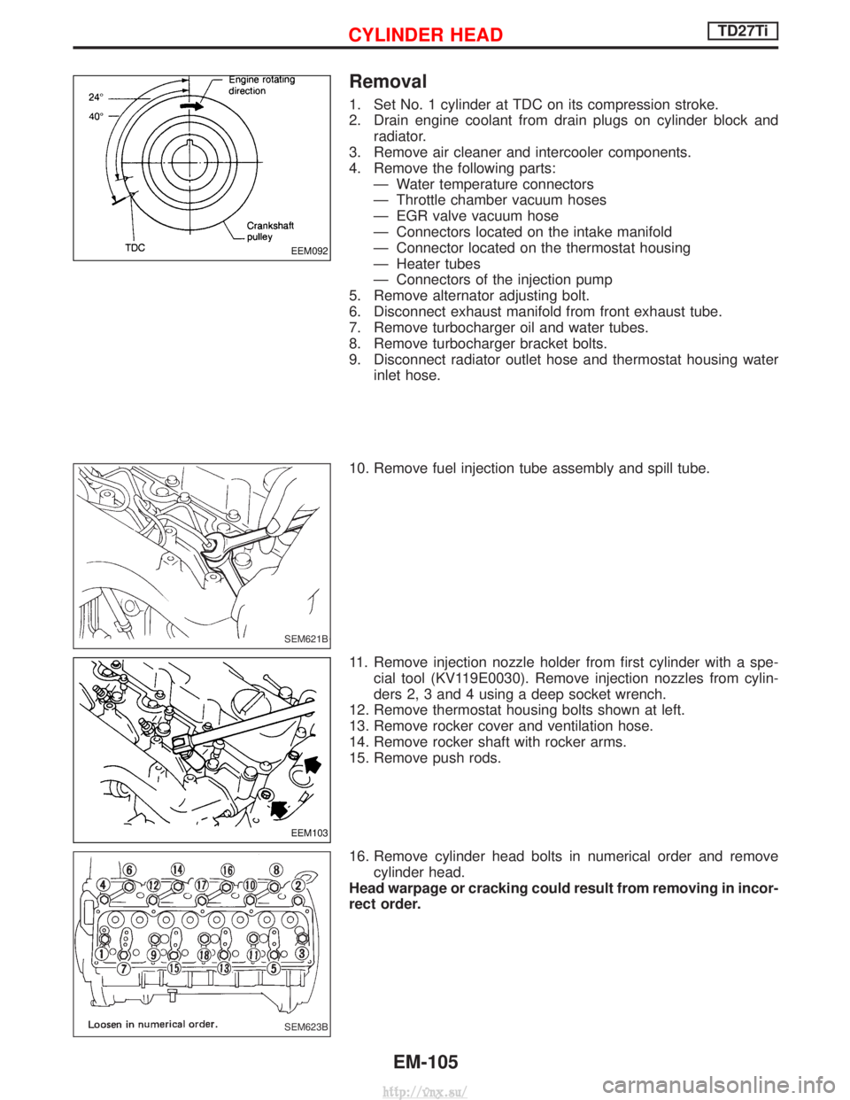
16. Remove cylinder head bolts in numerical order and remove cylinder head.
Head warpage or cracking could result from removing in incor-
rect order.
EEM092
SEM621B
EEM103
SEM623B
CYLINDER HEADTD27Ti
EM-105
http://vnx.su/
Page 197 of 1833
Disassembly
1. Remove following parts:
IEGR tube
I Intake manifold
I Heat shield plates
I Exhaust manifold
I Thermostat housing
I Alternator adjusting bar & engine slinger
I Glow plate and glow plugs
2. Remove valve component parts with Tool.
3. Remove valve oil seals with Tool.
4. Disassemble rocker shaft assembly.
a. Remove rocker shaft lock bolt.
b. Remove valve rocker and rocker shaft bracket.
If it is difficult to remove rocker shaft brackets, immerse rocker
shaft assembly in oil of 70ÉC (158ÉF) for a few minutes and
then remove brackets.
SEM624B
SEM625B
SEM626B
NEM160
CYLINDER HEADTD27Ti
EM-106
http://vnx.su/
Page 207 of 1833
6. Install rocker cover.
IBe sure to tighten bolts in the order shown in the illustration.
I When replacing rocker cover gasket, bend slit of rocker cover
baffle plate a little to hold the gasket. Do not twist gasket.
7. Install glow plugs and glow plate.
8. Install new top nozzle gasket and injection nozzle.
9. Install thermostat housing bolts shown at left.
10. Install spill tube and injection tube. Spill tube nut:
:39-49N ×m (4.0 - 5.0 kg-m, 29 - 36 ft-lb)
Injection tubes:
:20-25N ×m (2.0 - 2.5 kg-m, 14 - 18 ft-lb)
11. Connect thermostat housing water inlet hose and radiator hose.
12. Install all removed parts in reverse order of removal.
13. After assembling all disassembled parts, fill radiator and engine with new coolant up to filler opening.
Refer to MA section.
NEM163
SEM618B
EEM103
SEM621B
CYLINDER HEADTD27Ti
Installation (Cont'd)
EM-116
http://vnx.su/
Page 242 of 1833

ENGINE LUBRICATION &COOLING SYSTEMS
SECTION
LC
CONTENTS
ZD
PRECAUTIONS AND PREPARATION ............................2
Liquid Gasket Application Procedure ..........................2
Special Service Tools ..................................................2
ENGINE LUBRICATION SYSTEM ..................................3
Lubricating Circuit ........................................................3
Oil Pressure Check......................................................4
Oil Pump ......................................................................5
Oil Jet........................................................................\
...7
Oil Cooler .....................................................................8
ENGINE COOLING SYSTEM ..........................................9
Cooling Circuit .............................................................9
System Check............................................................10
Water Pump ............................................................... 11
Thermostat .................................................................12
Water Outlet ...............................................................13
Radiator .....................................................................14
Cooling Fan (Crankshaft driven) ...............................15
EGR Cooler ...............................................................16
SERVICE DATA AND SPECIFICATIONS (SDS) ..........17
Engine Lubrication System ........................................17
Engine Cooling System .............................................17 TD27TiPREPARATION
..............................................................18
PRECAUTION ................................................................19
ENGINE LUBRICATION SYSTEM ................................20
Lubrication Circuit ......................................................20
Oil Pressure Check....................................................21
Oil Pump ....................................................................22
Oil Filter Bracket ........................................................24
Oil Cooler ...................................................................25
Oil Jet........................................................................\
.26
ENGINE COOLING SYSTEM ........................................27
Cooling Circuit ...........................................................27
System Inspection .....................................................28
Water Pump ...............................................................29
Thermostat .................................................................31
Radiator .....................................................................32
Cooling Fan ...............................................................33
SERVICE DATA AND SPECIFICATIONS (SDS) ..........34
Engine Lubrication System ........................................34
Engine Cooling System .............................................34
http://vnx.su/
Page 253 of 1833
INSPECTION
1. Check for badly rusted or corroded body assembly and vane.
2. Check for rough operation due to excessive end play.
CAUTION:
Do not disassemble water pump coupling assembly.
Thermostat
SLC374B
YLC032
ENGINE COOLING SYSTEMZD
Water Pump (Cont'd)LC-12
http://vnx.su/
Page 254 of 1833
REMOVAL AND INSTALLATION
1. Drain engine coolant. Refer to MA section, ªChanging EngineCoolantº.
2. Remove left side battery. (If so equipped)
3. Remove radiator upper hose.
4. Remove radiator shroud.
5. Remove intake air duct, inlet pipe.
6. Remove harness and connectors.
7. Install in reverse order of removal.
I After installation, run engine for a few minutes and check
for leaks.
I Be careful not to spill coolant in engine compartment. Use
a rag to absorb coolant.
INSPECTION
1. Check valve seating condition at ordinary temperatures. It
should seat tightly.
2. Check valve opening temperature and maximum valve lift.
Valve opening temperature ÉC (ÉF) 82 (180)
Maximum valve lift mm/ÉC (in/ÉF) 10/95 (0.39/203)
3. Then check if valve closes at 5ÉC (9ÉF) below valve opening
temperature.
Water Outlet
INSPECTION
Visual inspection for water leaks. If there is leakage, replace gas-
ket.
JLC384B
SLC695A
YLC033
ENGINE COOLING SYSTEMZD
Thermostat (Cont'd)
LC-13
http://vnx.su/
Page 258 of 1833

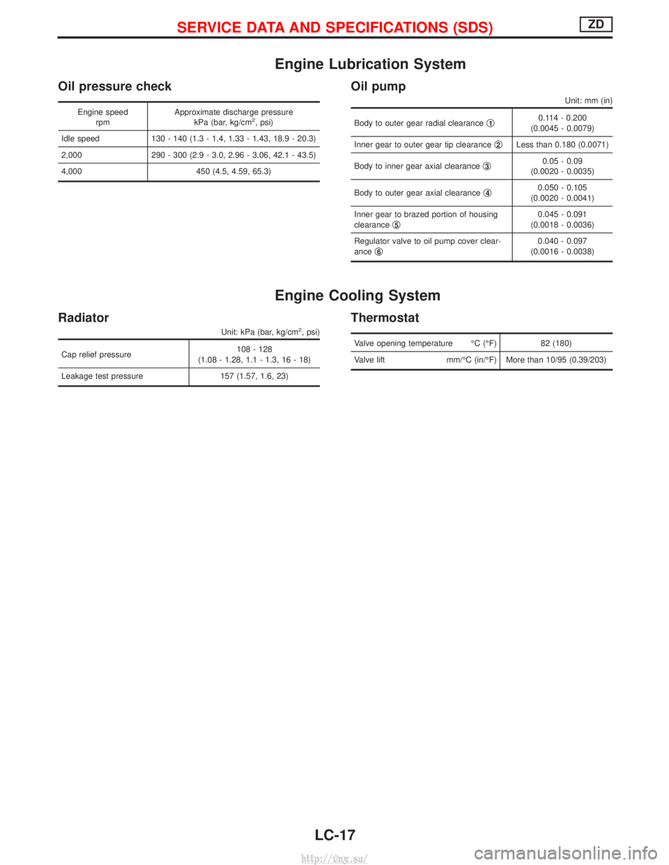
Engine Lubrication System
Oil pressure check
Engine speedrpm Approximate discharge pressure
kPa (bar, kg/cm2, psi)
Idle speed 130 - 140 (1.3 - 1.4, 1.33 - 1.43, 18.9 - 20.3)
2,000 290 - 300 (2.9 - 3.0, 2.96 - 3.06, 42.1 - 43.5)
4,000 450 (4.5, 4.59, 65.3)
Oil pump
Unit: mm (in)
Body to outer gear radial clearance q10.114 - 0.200
(0.0045 - 0.0079)
Inner gear to outer gear tip clearance q
2Less than 0.180 (0.0071)
Body to inner gear axial clearance q
30.05 - 0.09
(0.0020 - 0.0035)
Body to outer gear axial clearance q
40.050 - 0.105
(0.0020 - 0.0041)
Inner gear to brazed portion of housing
clearance q
50.045 - 0.091
(0.0018 - 0.0036)
Regulator valve to oil pump cover clear-
ance q
60.040 - 0.097
(0.0016 - 0.0038)
Engine Cooling System
Radiator
Unit: kPa (bar, kg/cm2, psi)
Cap relief pressure 108 - 128
(1.08 - 1.28, 1.1 - 1.3, 16 - 18)
Leakage test pressure 157 (1.57, 1.6, 23)
Thermostat
Valve opening temperature ÉC (ÉF) 82 (180)
Valve lift mm/ÉC (in/ÉF) More than 10/95 (0.39/203)
SERVICE DATA AND SPECIFICATIONS (SDS)ZD
LC-17
http://vnx.su/