2004 NISSAN TERRANO p1246
[x] Cancel search: p1246Page 280 of 1833
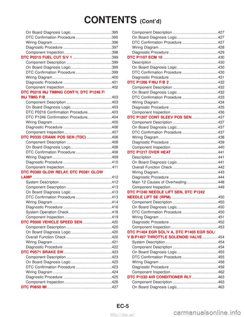
On Board Diagnosis Logic.......................................395
DTC Confirmation Procedure ..................................395
Wiring Diagram ........................................................396
Diagnostic Procedure ..............................................397
Component Inspection .............................................398
DTC P0215 FUEL CUT S/V 1 .....................................399
Component Description ...........................................399
On Board Diagnosis Logic.......................................399
DTC Confirmation Procedure ..................................399
Wiring Diagram ........................................................400
Diagnostic Procedure ..............................................401
Component Inspection .............................................402
DTC P0216 INJ TIMING CONT/V, DTC P1246 F/
INJ TIMG F/B ...............................................................403
Component Description ...........................................403
On Board Diagnosis Logic.......................................403
DTC P0216 Confirmation Procedure.......................403
DTC P1246 Confirmation Procedure.......................404
Wiring Diagram ........................................................405
Diagnostic Procedure ..............................................406
Component Inspection .............................................407
DTC P0335 CRANK POS SEN (TDC) ........................408
Component Description ...........................................408
On Board Diagnosis Logic.......................................408
DTC Confirmation Procedure ..................................408
Wiring Diagram ........................................................409
Diagnostic Procedure ..............................................410
Component Inspection ............................................. 411
DTC P0380 GLOW RELAY, DTC P0381 GLOW
LAMP ........................................................................\
...412
System Description ..................................................412
Component Description ...........................................413
On Board Diagnosis Logic.......................................413
DTC Confirmation Procedure ..................................413
Wiring Diagram ........................................................414
Diagnostic Procedure ..............................................416
System Operation Check.........................................418
Component Inspection .............................................419
DTC P0500 VEHICLE SPEED SEN ............................420
Component Description ...........................................420
On Board Diagnosis Logic.......................................420
Overall Function Check ...........................................420
Wiring Diagram ........................................................421
Diagnostic Procedure ..............................................422
DTC P0571 BRAKE SW ..............................................423
Component Description ...........................................423
On Board Diagnosis Logic.......................................423
DTC Confirmation Procedure ..................................423
Wiring Diagram ........................................................424
Diagnostic Procedure ..............................................425
Component Inspection .............................................426
DTC P0650 MI .............................................................427 Component Description ...........................................427
On Board Diagnosis Logic.......................................427
DTC Confirmation Procedure ..................................427
Wiring Diagram ........................................................428
Diagnostic Procedure ..............................................429
DTC P1107 ECM 10 ....................................................430
Description ...............................................................430
On Board Diagnosis Logic.......................................430
DTC Confirmation Procedure ..................................430
Diagnostic Procedure ..............................................431
DTC P1206 F/INJ F/B 2 ..............................................432
Component Description ...........................................432
On Board Diagnosis Logic.......................................432
DTC Confirmation Procedure ..................................433
Wiring Diagram ........................................................434
Diagnostic Procedure ..............................................435
Component Inspection .............................................436
DTC P1207 CONT SLEEV POS SEN .........................437
Component Description ...........................................437
On Board Diagnosis Logic.......................................437
DTC Confirmation Procedure ..................................437
Wiring Diagram ........................................................438
Diagnostic Procedure ..............................................439
Component Inspection .............................................440
DTC P1217 OVER HEAT ............................................441
Description ...............................................................441
On Board Diagnosis Logic.......................................441
Overall Function Check ...........................................442
Wiring Diagram ........................................................443
Diagnostic Procedure ..............................................444
Main 12 Causes of Overheating..............................448
Component Inspection .............................................449
DTC P1240 NEEDLE LIFT SEN, DTC P1242
NEEDLE LIFT SE (RPM) .............................................450
Component Description ...........................................450
On Board Diagnosis Logic.......................................450
DTC Confirmation Procedure ..................................450
Wiring Diagram ........................................................451
Diagnostic Procedure ..............................................452
Component Inspection .............................................453
DTC P1404 EGR SOL/V A, DTC P1405 EGR SOL/
V B/P1407 THROTTLE SOLENOID VALVE ...............454
System Description ..................................................454
Component Description ...........................................454
On Board Diagnosis Logic.......................................455
DTC Confirmation Procedure ..................................455
Wiring Diagram ........................................................456
Diagnostic Procedure ..............................................459
Component Inspection .............................................462
DTC P1530 AIR CONDITIONER RLY .........................463
Component Description ...........................................463
On Board Diagnosis Logic.......................................463
CONTENTS(Cont'd)
EC-5
http://vnx.su/
Page 588 of 1833
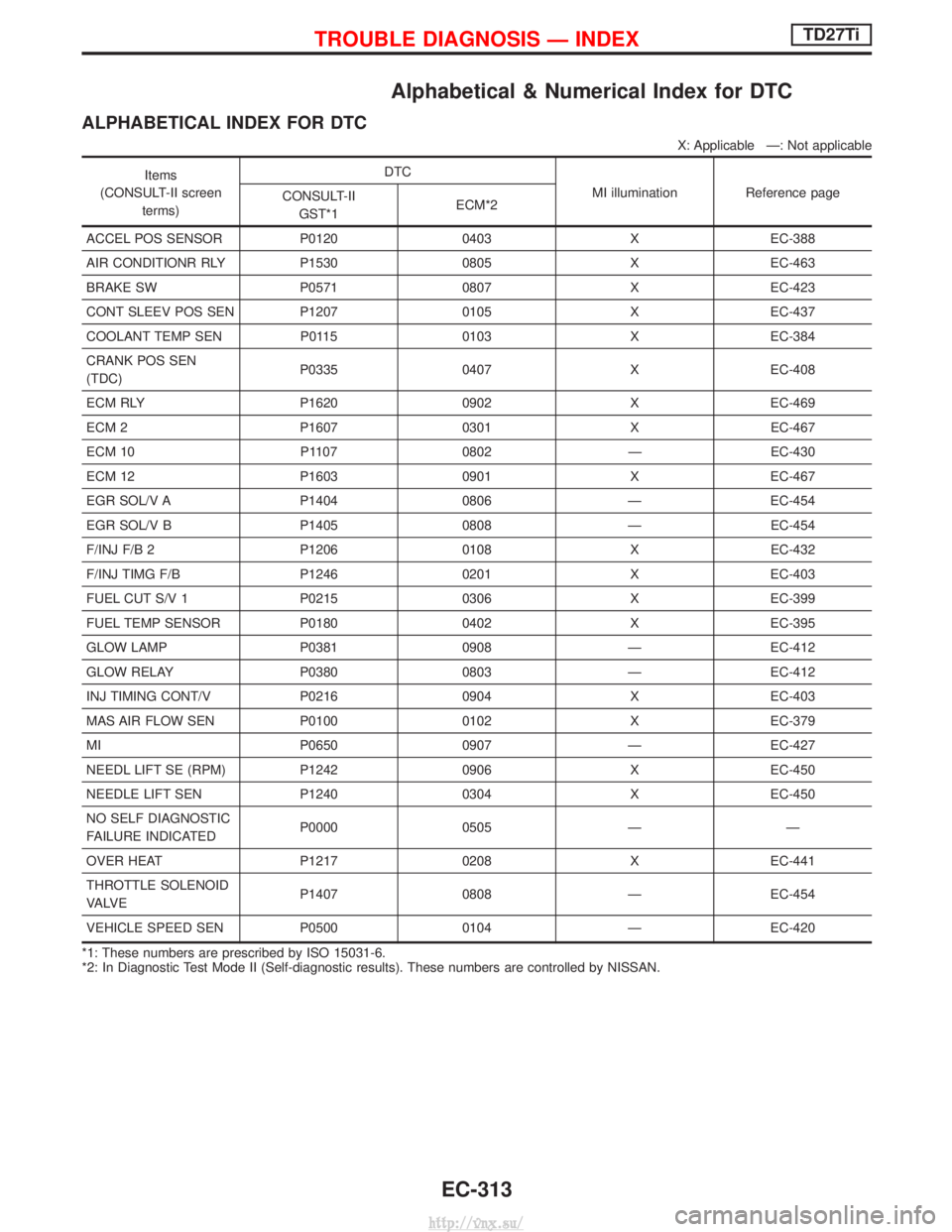
Alphabetical & Numerical Index for DTC
ALPHABETICAL INDEX FOR DTC
X: Applicable Ð: Not applicable
Items
(CONSULT-II screen terms) DTC
MI illuminationReference page
CONSULT-II
GST*1 ECM*2
ACCEL POS SENSOR P0120 0403 X EC-388
AIR CONDITIONR RLY P1530 0805 X EC-463
BRAKE SW P0571 0807 X EC-423
CONT SLEEV POS SEN P1207 0105 X EC-437
COOLANT TEMP SEN P0115 0103 X EC-384
CRANK POS SEN
(TDC) P0335 0407 X EC-408
ECM RLY P1620 0902 X EC-469
ECM 2 P1607 0301 X EC-467
ECM 10 P1107 0802 Ð EC-430
ECM 12 P1603 0901 X EC-467
EGR SOL/V A P1404 0806 Ð EC-454
EGR SOL/V B P1405 0808 Ð EC-454
F/INJ F/B 2 P1206 0108 X EC-432
F/INJ TIMG F/B P1246 0201 X EC-403
FUEL CUT S/V 1 P0215 0306 X EC-399
FUEL TEMP SENSOR P0180 0402 X EC-395
GLOW LAMP P0381 0908 Ð EC-412
GLOW RELAY P0380 0803 Ð EC-412
INJ TIMING CONT/V P0216 0904 X EC-403
MAS AIR FLOW SEN P0100 0102 X EC-379
MI P0650 0907 Ð EC-427
NEEDL LIFT SE (RPM) P1242 0906 X EC-450
NEEDLE LIFT SEN P1240 0304 X EC-450
NO SELF DIAGNOSTIC
FAILURE INDICATED P0000 0505 Ð Ð
OVER HEAT P1217 0208 X EC-441
THROTTLE SOLENOID
VA LV E P1407 0808 Ð EC-454
VEHICLE SPEED SEN P0500 0104 Ð EC-420
*1: These numbers are prescribed by ISO 15031-6.
*2: In Diagnostic Test Mode II (Self-diagnostic results). These numbers are controlled by NISSAN.
TROUBLE DIAGNOSIS Ð INDEXTD27Ti
EC-313
http://vnx.su/
Page 589 of 1833
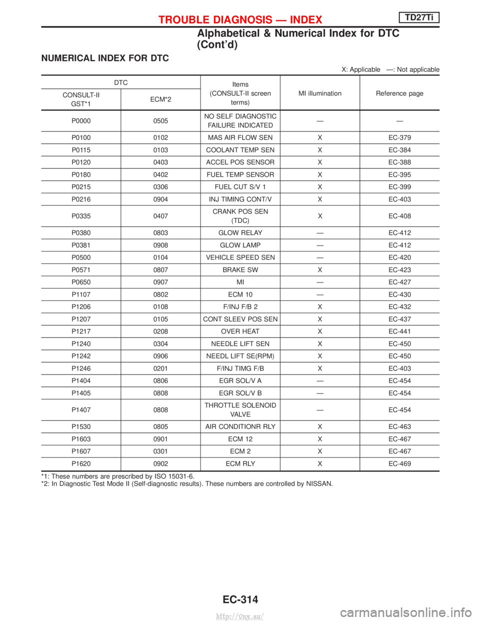
NUMERICAL INDEX FOR DTC
X: Applicable Ð: Not applicable
DTCItems
(CONSULT-II screen terms) MI illumination Reference page
CONSULT-II
GST*1 ECM*2
P0000 0505 NO SELF DIAGNOSTIC
FAILURE INDICATED ÐÐ
P0100 0102 MAS AIR FLOW SEN X EC-379 P0115 0103 COOLANT TEMP SEN X EC-384
P0120 0403 ACCEL POS SENSOR X EC-388
P0180 0402 FUEL TEMP SENSOR X EC-395
P0215 0306 FUEL CUT S/V 1 X EC-399
P0216 0904 INJ TIMING CONT/V X EC-403
P0335 0407 CRANK POS SEN
(TDC) X EC-408
P0380 0803 GLOW RELAY Ð EC-412
P0381 0908 GLOW LAMP Ð EC-412
P0500 0104 VEHICLE SPEED SEN Ð EC-420
P0571 0807 BRAKE SW X EC-423
P0650 0907 MI Ð EC-427 P1107 0802 ECM 10 Ð EC-430
P1206 0108 F/INJ F/B 2 X EC-432
P1207 0105 CONT SLEEV POS SEN X EC-437
P1217 0208 OVER HEAT X EC-441
P1240 0304 NEEDLE LIFT SEN X EC-450
P1242 0906 NEEDL LIFT SE(RPM) X EC-450
P1246 0201 F/INJ TIMG F/B X EC-403
P1404 0806 EGR SOL/V A Ð EC-454
P1405 0808 EGR SOL/V B Ð EC-454
P1407 0808 THROTTLE SOLENOID
VA LV E Ð EC-454
P1530 0805 AIR CONDITIONR RLY X EC-463
P1603 0901 ECM 12 X EC-467
P1607 0301 ECM 2 X EC-467
P1620 0902 ECM RLY X EC-469
*1: These numbers are prescribed by ISO 15031-6.
*2: In Diagnostic Test Mode II (Self-diagnostic results). These numbers are controlled by NISSAN.
TROUBLE DIAGNOSIS Ð INDEXTD27Ti
Alphabetical & Numerical Index for DTC
(Cont'd)
EC-314
http://vnx.su/
Page 678 of 1833

Component Description
INJECTION TIMING CONTROL VALVE
The injection timing control valve is built into the fuel injection
pump. It controls the timer piston to change the fuel injection tim-
ing.
The timing control valve is a solenoid valve located in the line
between high-pressure chamber and low-pressure chamber. It
changes fuel pressure in the high-pressure chamber.
When current flows through the solenoid (the solenoid turns ON),
the timing control valve opens, advancing fuel injection timing.
When current does not flow through it, the timing control valve
closes, retarding injection timing.
The ECM emits an ON-OFF duty signal. The longer the OFF-
duration, the greater the advance angle. The longer the
ON-duration, the greater the retard angle. This means that chang-
ing the ON-OFF duty ratio makes it possible to achieve an optimal
advance angle and accurately control fuel injection timing.
On Board Diagnosis Logic
DTCMalfunction is detected when .... Check Items
(Possible cause)
P0216
0904 I
Injection timing control valve circuit is open or
shorted. I
Harness or connectors
(The injection timing control valve circuit is open or
shorted)
I Injection timing control valve
P1246
0201 I
Injection timing feedback system does not operate
properly. (This system consists essentially of ECM,
injection timing control valve and needle lift sensor.) I
Harness or connectors
[Injection timing control valve, needle lift sensor,
crankshaft position sensor (TDC) circuits]
I Injection timing control valve
I Needle lift sensor
I Crankshaft position sensor (TDC)
I Air in fuel line
DTC P0216 Confirmation Procedure
WITH CONSULT-II
1) Turn ignition switch to ªONº position.
2) Select ªDATA MONITORº mode with CONSULT-II.
3) Wait at least 2 seconds.
WITHOUT CONSULT-II
1) Turn ignition switch to ªONº position.
2) Wait at least 2 seconds.
3) Turn ignition switch to ªLOCKº position, wait at least 5 seconds
and then turn to ªONº position.
4) Perform ªDiagnostic Test Mode IIº (Self-diagnostic results).
SEF638S
DTC P0216 INJ TIMING CONT/V, DTC P1246 F/INJ TIMG F/BTD27Ti
EC-403
http://vnx.su/
Page 679 of 1833
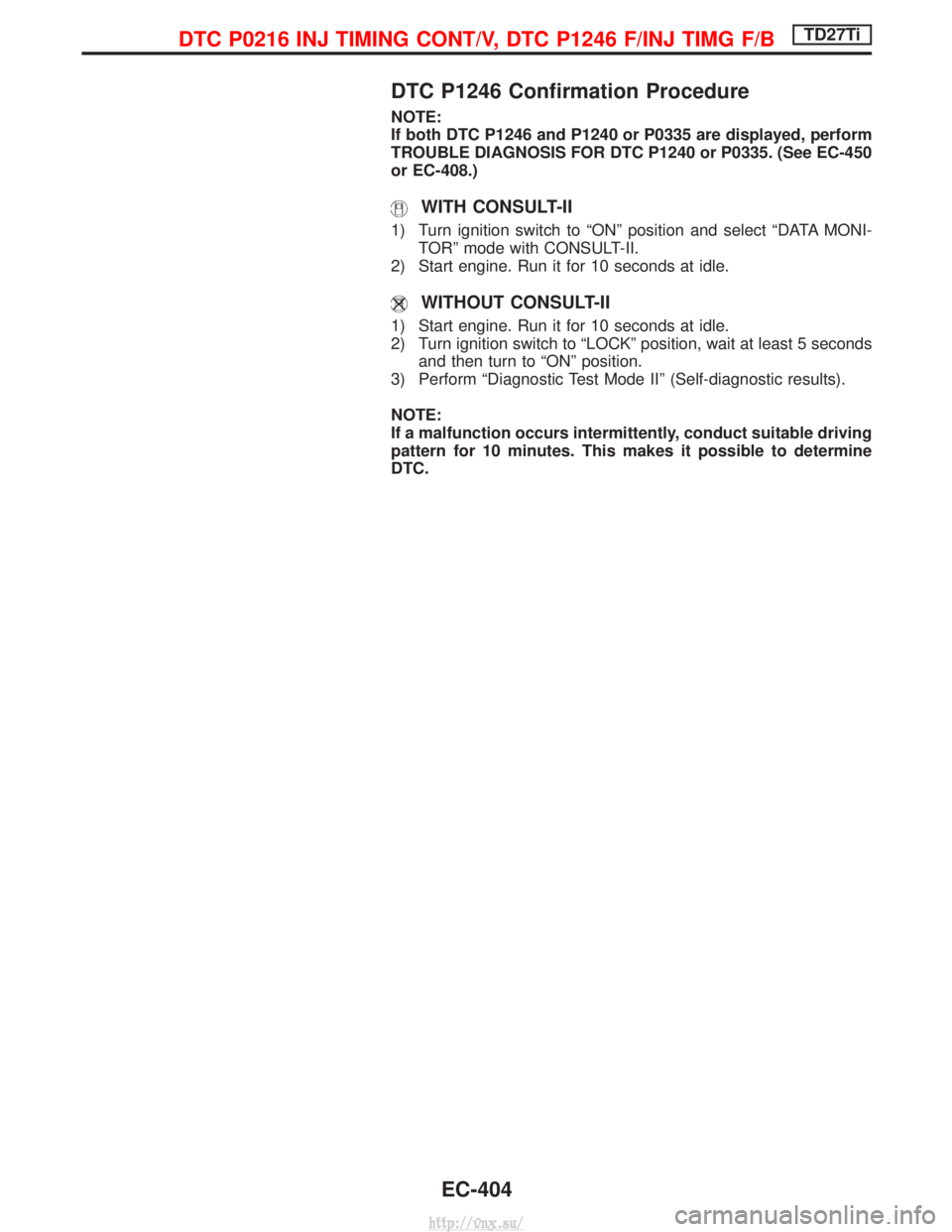
DTC P1246 Confirmation Procedure
NOTE:
If both DTC P1246 and P1240 or P0335 are displayed, perform
TROUBLE DIAGNOSIS FOR DTC P1240 or P0335. (See EC-450
or EC-408.)
WITH CONSULT-II
1) Turn ignition switch to ªONº position and select ªDATA MONI-TORº mode with CONSULT-II.
2) Start engine. Run it for 10 seconds at idle.
WITHOUT CONSULT-II
1) Start engine. Run it for 10 seconds at idle.
2) Turn ignition switch to ªLOCKº position, wait at least 5 seconds and then turn to ªONº position.
3) Perform ªDiagnostic Test Mode IIº (Self-diagnostic results).
NOTE:
If a malfunction occurs intermittently, conduct suitable driving
pattern for 10 minutes. This makes it possible to determine
DTC.
DTC P0216 INJ TIMING CONT/V, DTC P1246 F/INJ TIMG F/BTD27Ti
EC-404
http://vnx.su/
Page 680 of 1833

Wiring Diagram
YEC678A
DTC P0216 INJ TIMING CONT/V, DTC P1246 F/INJ TIMG F/BTD27Ti
EC-405
http://vnx.su/
Page 681 of 1833
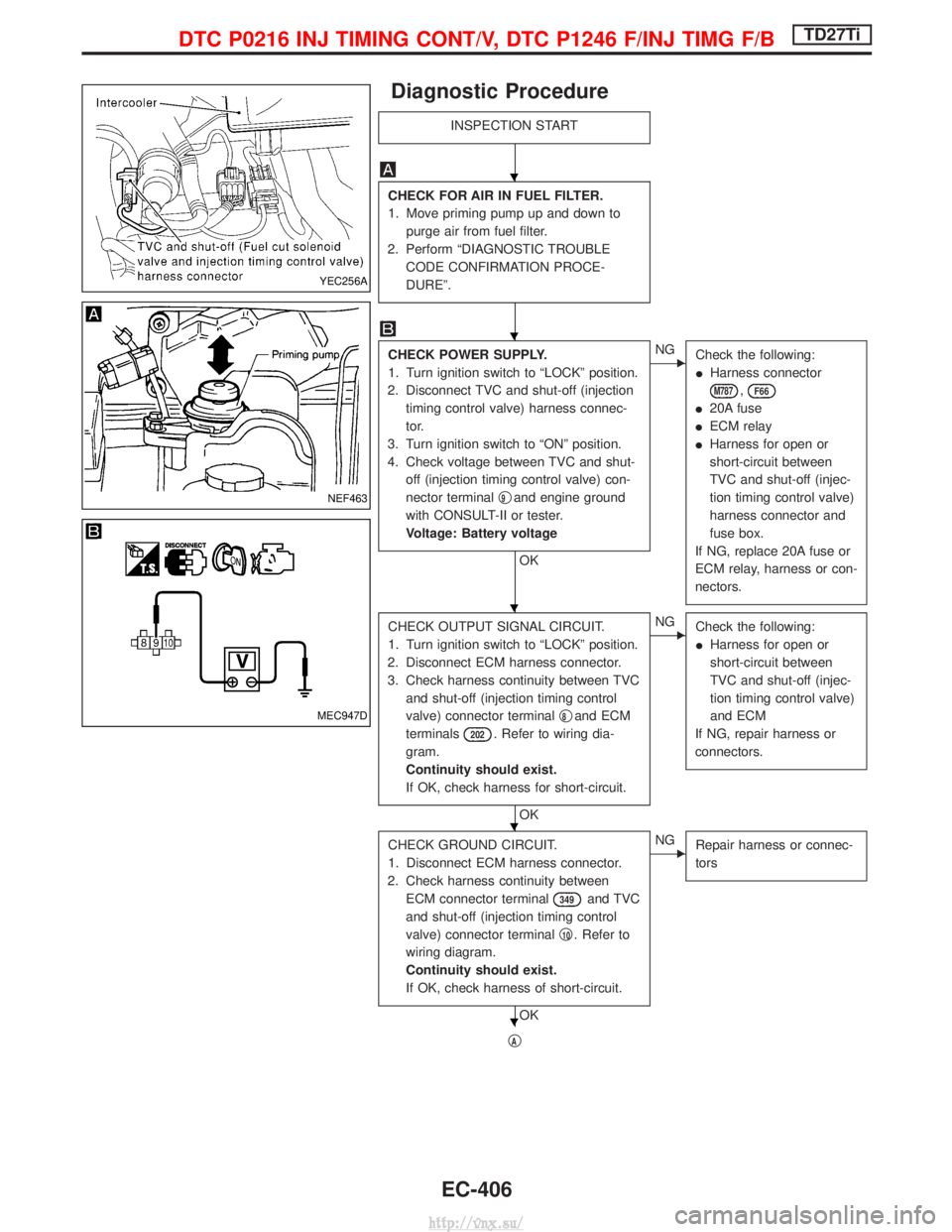
Diagnostic Procedure
INSPECTION START
CHECK FOR AIR IN FUEL FILTER.
1. Move priming pump up and down topurge air from fuel filter.
2. Perform ªDIAGNOSTIC TROUBLE CODE CONFIRMATION PROCE-
DUREº.
CHECK POWER SUPPLY.
1. Turn ignition switch to ªLOCKº position.
2. Disconnect TVC and shut-off (injection timing control valve) harness connec-
tor.
3. Turn ignition switch to ªONº position.
4. Check voltage between TVC and shut- off (injection timing control valve) con-
nector terminal q
9and engine ground
with CONSULT-II or tester.
Voltage: Battery voltage
OK
ENG Check the following:
IHarness connector
M787,F66
I20A fuse
I ECM relay
I Harness for open or
short-circuit between
TVC and shut-off (injec-
tion timing control valve)
harness connector and
fuse box.
If NG, replace 20A fuse or
ECM relay, harness or con-
nectors.
CHECK OUTPUT SIGNAL CIRCUIT.
1. Turn ignition switch to ªLOCKº position.
2. Disconnect ECM harness connector.
3. Check harness continuity between TVC and shut-off (injection timing control
valve) connector terminal q
8and ECM
terminals
202. Refer to wiring dia-
gram.
Continuity should exist.
If OK, check harness for short-circuit.
OK
ENG Check the following:
IHarness for open or
short-circuit between
TVC and shut-off (injec-
tion timing control valve)
and ECM
If NG, repair harness or
connectors.
CHECK GROUND CIRCUIT.
1. Disconnect ECM harness connector.
2. Check harness continuity between ECM connector terminal
349and TVC
and shut-off (injection timing control
valve) connector terminal q
10. Refer to
wiring diagram.
Continuity should exist.
If OK, check harness of short-circuit.
OK
ENG Repair harness or connec-
tors
qA
YEC256A
NEF463
MEC947D
H
H
H
H
H
DTC P0216 INJ TIMING CONT/V, DTC P1246 F/INJ TIMG F/BTD27Ti
EC-406
http://vnx.su/
Page 682 of 1833
![NISSAN TERRANO 2004 Service Repair Manual qA
CHECK COMPONENT
[TVC and shut-off (Injection timing control
valve)].
Refer to ªCOMPONENT INSPECTIONº on
page EC-407.
OK
ENGReplace injection timing
control valve.
Disconnect and reconnect harness NISSAN TERRANO 2004 Service Repair Manual qA
CHECK COMPONENT
[TVC and shut-off (Injection timing control
valve)].
Refer to ªCOMPONENT INSPECTIONº on
page EC-407.
OK
ENGReplace injection timing
control valve.
Disconnect and reconnect harness](/manual-img/5/57394/w960_57394-681.png)
qA
CHECK COMPONENT
[TVC and shut-off (Injection timing control
valve)].
Refer to ªCOMPONENT INSPECTIONº on
page EC-407.
OK
ENGReplace injection timing
control valve.
Disconnect and reconnect harness con-
nectors in the circuit. Then retest.
Trouble is not fixed.
Check ECM pin terminals for damage and
check the connection of ECM harness
connector. Reconnect ECM harness con-
nector and retest.
INSPECTION END
Component Inspection
[TVC AND SHUT-OFF (INJECTION TIMING CONTROL
VALVE)]
1. Disconnect TVC and shut-off (injection timing control valve) harness connector.
2. Check resistance between terminals q
9andq10.
Resistance: Approximately 15W [at 25ÉC (77ÉF)]
If NG, replace injection timing control valve.
MEC958D
H
H
H
H
DTC P0216 INJ TIMING CONT/V, DTC P1246 F/INJ TIMG F/BTD27Ti
Diagnostic Procedure (Cont'd)
EC-407
http://vnx.su/