2004 NISSAN TERRANO turn signal
[x] Cancel search: turn signalPage 45 of 1833
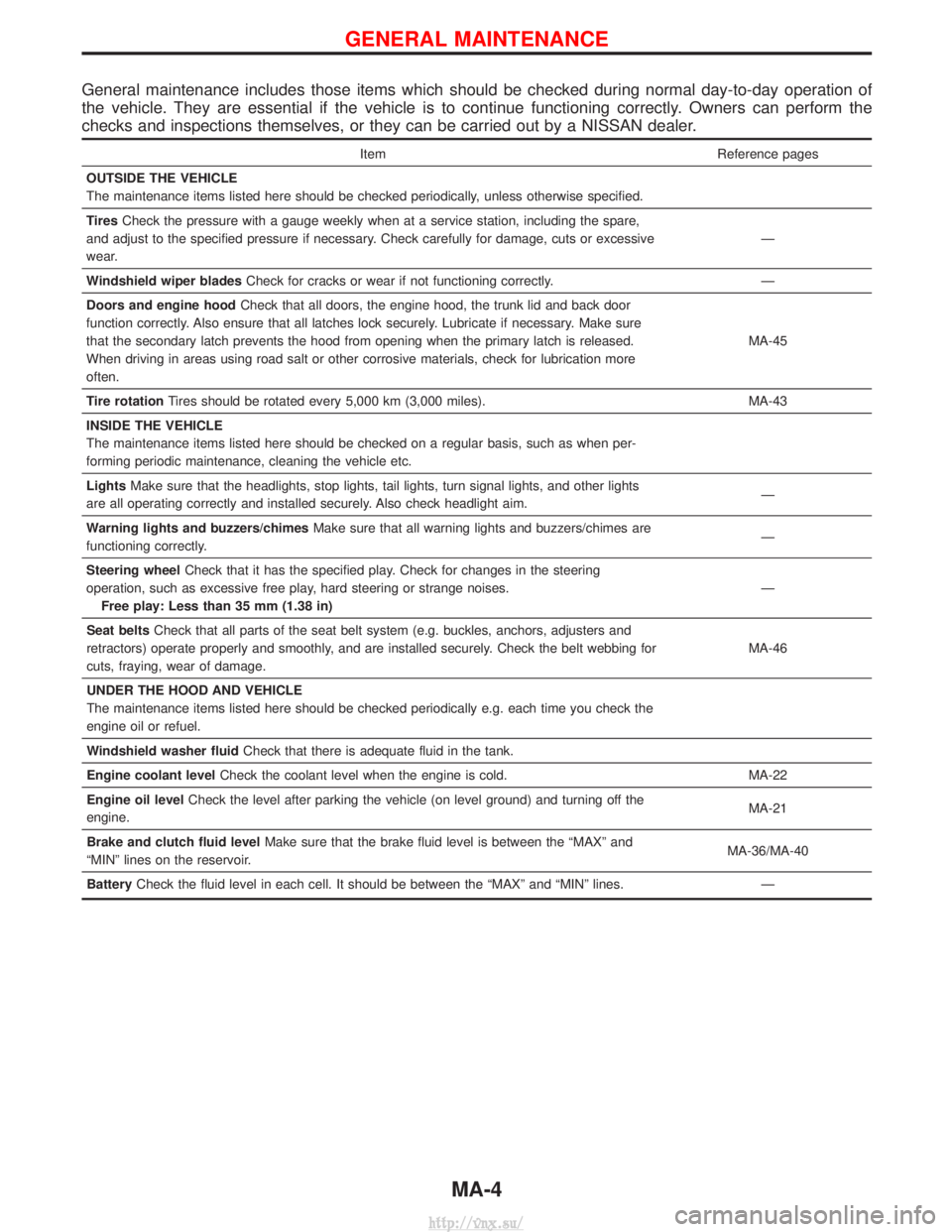
General maintenance includes those items which should be checked during normal day-to-day operation of
the vehicle. They are essential if the vehicle is to continue functioning correctly. Owners can perform the
checks and inspections themselves, or they can be carried out by a NISSAN dealer.
ItemReference pages
OUTSIDE THE VEHICLE
The maintenance items listed here should be checked periodically, unless otherwise specified.
Tires Check the pressure with a gauge weekly when at a service station, including the spare,
and adjust to the specified pressure if necessary. Check carefully for damage, cuts or excessive
wear. Ð
Windshield wiper blades Check for cracks or wear if not functioning correctly. Ð
Doors and engine hood Check that all doors, the engine hood, the trunk lid and back door
function correctly. Also ensure that all latches lock securely. Lubricate if necessary. Make sure
that the secondary latch prevents the hood from opening when the primary latch is released.
When driving in areas using road salt or other corrosive materials, check for lubrication more
often. MA-45
Tire rotation Tires should be rotated every 5,000 km (3,000 miles). MA-43
INSIDE THE VEHICLE
The maintenance items listed here should be checked on a regular basis, such as when per-
forming periodic maintenance, cleaning the vehicle etc.
Lights Make sure that the headlights, stop lights, tail lights, turn signal lights, and other lights
are all operating correctly and installed securely. Also check headlight aim. Ð
Warning lights and buzzers/chimes Make sure that all warning lights and buzzers/chimes are
functioning correctly. Ð
Steering wheel Check that it has the specified play. Check for changes in the steering
operation, such as excessive free play, hard steering or strange noises. Free play: Less than 35 mm (1.38 in) Ð
Seat belts Check that all parts of the seat belt system (e.g. buckles, anchors, adjusters and
retractors) operate properly and smoothly, and are installed securely. Check the belt webbing for
cuts, fraying, wear of damage. MA-46
UNDER THE HOOD AND VEHICLE
The maintenance items listed here should be checked periodically e.g. each time you check the
engine oil or refuel.
Windshield washer fluid Check that there is adequate fluid in the tank.
Engine coolant level Check the coolant level when the engine is cold. MA-22
Engine oil level Check the level after parking the vehicle (on level ground) and turning off the
engine. MA-21
Brake and clutch fluid level Make sure that the brake fluid level is between the ªMAXº and
ªMINº lines on the reservoir. MA-36/MA-40
Battery Check the fluid level in each cell. It should be between the ªMAXº and ªMINº lines. Ð
GENERAL MAINTENANCE
MA-4
http://vnx.su/
Page 297 of 1833

Fuel Injection Timing Control System
DESCRIPTION
The target fuel injection timing in accordance with the engine speed and the fuel injection amount are recorded
as a map in the ECM beforehand. The ECM and the injection pump control unit exchange signals and per-
form feedback control for optimum injection timing in accordance with the map.
Air Conditioning Cut Control
DESCRIPTION
Input/output signal chart
SensorInput Signal to ECM ECM Function Actuator
Air conditioner switch Air conditioner ªONº signal
Air conditioner cut
controlAir conditioner relay
Accelerator position sensor
Accelerator valve opening
angle
Vehicle speed sensor Vehicle speed
Engine coolant temperature sensor Engine coolant temperature
System description
This system improves acceleration when the air conditioner is used.
When the accelerator pedal is fully depressed, the air conditioner is turned off for a few seconds.
When engine coolant temperature becomes excessively high, the air conditioner is turned off. This continues
until the engine coolant temperature returns to normal.
Fuel Cut Control (at no load & high engine
speed)
DESCRIPTION
Input/output signal chart
SensorInput Signal to ECM ECM Function Actuator
Vehicle speed sensor Vehicle speed
Fuel cut controlElectronic control fuel injec-
tion pump
Park/Neutral position (PNP) switch
Neutral position
Accelerator position switch or Accelerator
switch (F/C) Accelerator position
Engine coolant temperature sensor Engine coolant temperature
Crankshaft position sensor (TDC) Engine speed
If the engine speed is above 2,700 rpm with no load (for example, in neutral and engine speed over 2,700
rpm) fuel will be cut off after some time. The exact time when the fuel is cut off varies based on engine speed.
Fuel cut will operate until the engine speed reaches 1,500 rpm, then fuel cut is cancelled.
NOTE:
This function is different from deceleration control listed under ªFuel Injection Control Systemº, EC-20.
ENGINE AND EMISSION BASIC CONTROL SYSTEM
DESCRIPTIONZD30DDTi
EC-22
http://vnx.su/
Page 338 of 1833
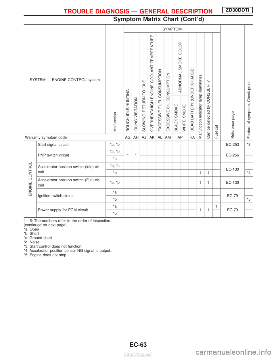
SYSTEM Ð ENGINE CONTROL system
Malfunction
SYMPTOM
Reference page
Feature of symptom, Check pointROUGH IDLE/HUNTING
IDLING VIBRATION
SLOW/NO RETURN TO IDLE
OVERHEAT/HIGH ENGINE COOLANT TEMPERATURE
EXCESSIVE FUEL CONSUMPTION
EXCESSIVE OIL CONSUMPTION
ABNORMAL SMOKE COLOR
DEAD BATTERY (UNDER CHARGE)
Malfunction indicator lamp illuminates.
Can be detected by CONSULT-II?
Fuel cut BLACK SMOKE
WHITE SMOKEWarranty symptom code
AG AH AJ AK AL AM AP HA
ENGINE CONTROL
Start signal circuit*a, *b EC-253 *3
PNP switch circuit *a, *b
1 1 EC-256
*c
Accelerator position switch (Idle) cir-
cuit *a, *c
EC-130
*b 1 1 *4
Accelerator position switch (Full) cir-
cuit *a, *b 1 1 EC-130
Ignition switch circuit *a
EC-79
*b *5
Power supply for ECM circuit *a
111
EC-79
*b
1 - 5: The numbers refer to the order of inspection.
(continued on next page)
*a: Open
*b: Short
*c: Ground short
*d: Noise
*3: Start control does not function.
*4: Accelerator position sensor NG signal is output.
*5: Engine does not stop.
TROUBLE DIAGNOSIS Ð GENERAL DESCRIPTIONZD30DDTi
Symptom Matrix Chart (Cont'd)
EC-63
http://vnx.su/
Page 341 of 1833
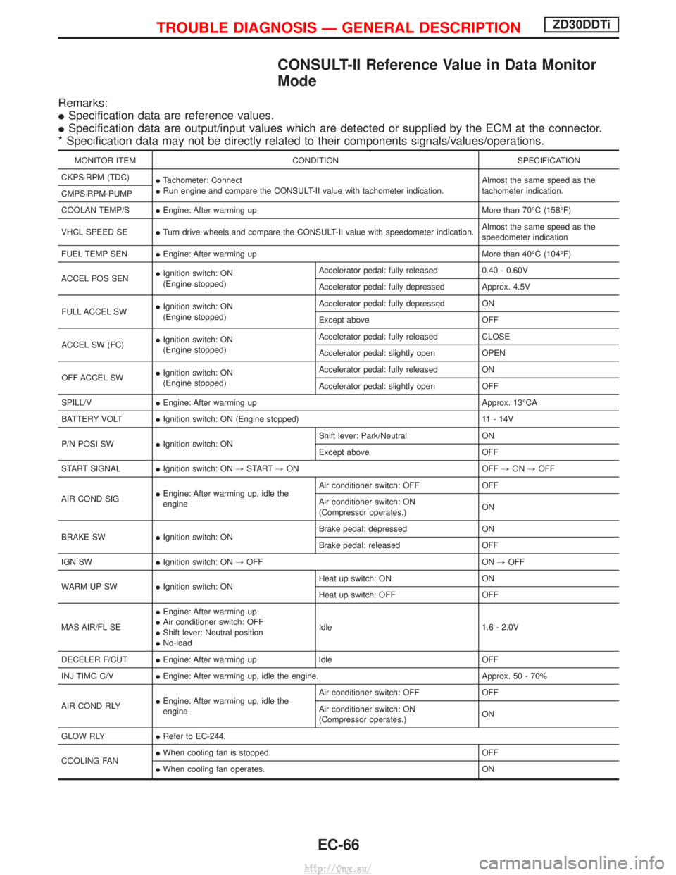
CONSULT-II Reference Value in Data Monitor
Mode
Remarks:
ISpecification data are reference values.
I Specification data are output/input values which are detected or supplied by the ECM at the connector.
* Specification data may not be directly related to their components signals/values/operations.
MONITOR ITEM CONDITION SPECIFICATION
CKPS×RPM (TDC) ITachometer: Connect
I Run engine and compare the CONSULT-II value with tachometer indication. Almost the same speed as the
tachometer indication.
CMPS×RPM-PUMP
COOLAN TEMP/S IEngine: After warming up More than 70ÉC (158ÉF)
VHCL SPEED SE ITurn drive wheels and compare the CONSULT-II value with speedometer indication. Almost the same speed as the
speedometer indication
FUEL TEMP SEN IEngine: After warming up More than 40ÉC (104ÉF)
ACCEL POS SEN I
Ignition switch: ON
(Engine stopped) Accelerator pedal: fully released
0.40 - 0.60V
Accelerator pedal: fully depressed Approx. 4.5V
FULL ACCEL SW I
Ignition switch: ON
(Engine stopped) Accelerator pedal: fully depressed ON
Except above
OFF
ACCEL SW (FC) I
Ignition switch: ON
(Engine stopped) Accelerator pedal: fully released
CLOSE
Accelerator pedal: slightly open OPEN
OFF ACCEL SW I
Ignition switch: ON
(Engine stopped) Accelerator pedal: fully released
ON
Accelerator pedal: slightly open OFF
SPILL/V IEngine: After warming up Approx. 13ÉCA
BATTERY VOLT IIgnition switch: ON (Engine stopped) 11 - 14V
P/N POSI SW IIgnition switch: ON Shift lever: Park/Neutral
ON
Except above OFF
START SIGNAL IIgnition switch: ON ,START ,ON OFF ,ON ,OFF
AIR COND SIG I
Engine: After warming up, idle the
engine Air conditioner switch: OFF OFF
Air conditioner switch: ON
(Compressor operates.)
ON
BRAKE SW IIgnition switch: ON Brake pedal: depressed ON
Brake pedal: released OFF
IGN SW IIgnition switch: ON ,OFF ON ,OFF
WARM UP SW IIgnition switch: ON Heat up switch: ON ON
Heat up switch: OFF OFF
MAS AIR/FL SE I
Engine: After warming up
I Air conditioner switch: OFF
I Shift lever: Neutral position
I No-load Idle 1.6 - 2.0V
DECELER F/CUT IEngine: After warming up Idle OFF
INJ TIMG C/V IEngine: After warming up, idle the engine. Approx. 50 - 70%
AIR COND RLY I
Engine: After warming up, idle the
engine Air conditioner switch: OFF OFF
Air conditioner switch: ON
(Compressor operates.)
ON
GLOW RLY IRefer to EC-244.
COOLING FAN I
When cooling fan is stopped. OFF
I When cooling fan operates. ON
TROUBLE DIAGNOSIS Ð GENERAL DESCRIPTIONZD30DDTi
EC-66
http://vnx.su/
Page 345 of 1833
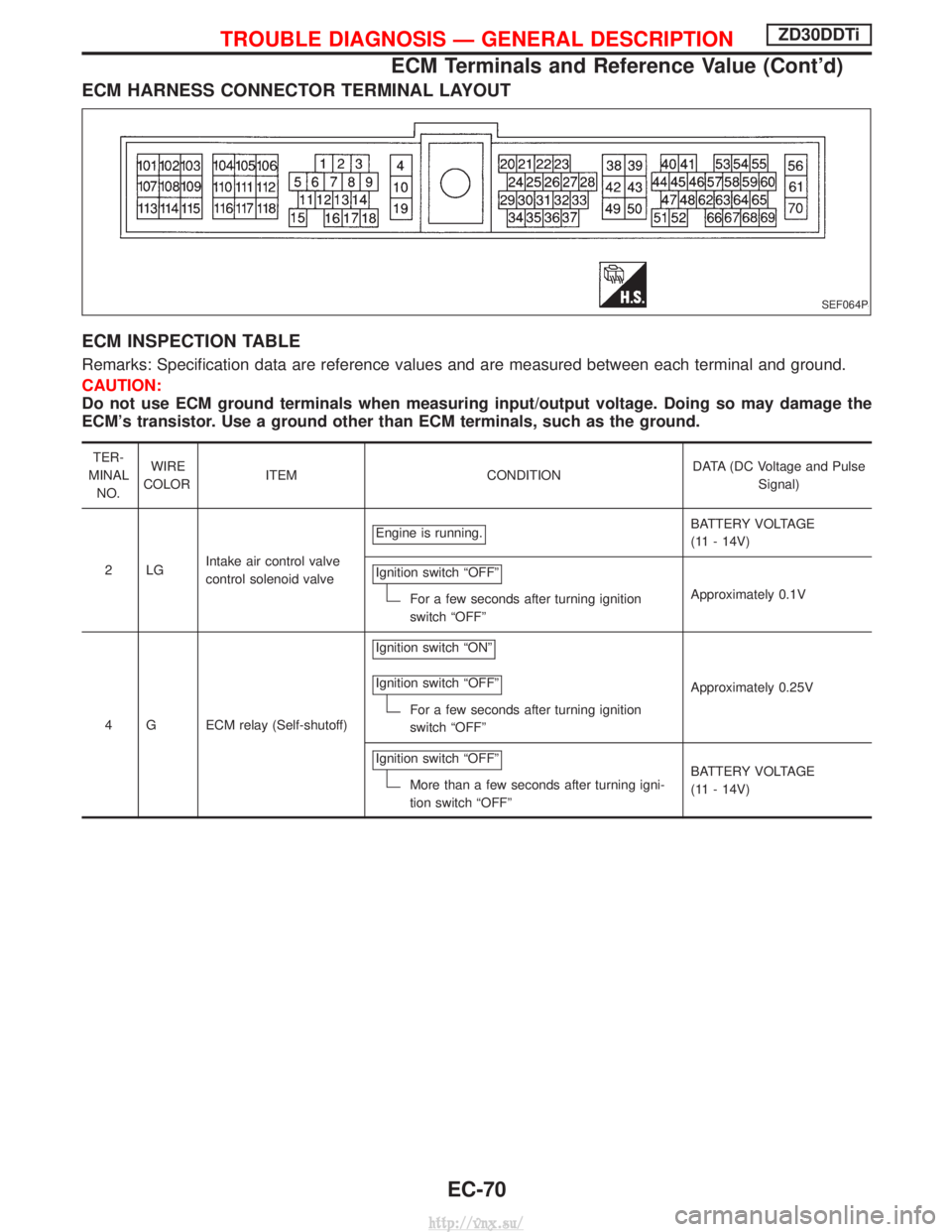
ECM HARNESS CONNECTOR TERMINAL LAYOUT
ECM INSPECTION TABLE
Remarks: Specification data are reference values and are measured between each terminal and ground.
CAUTION:
Do not use ECM ground terminals when measuring input/output voltage. Doing so may damage the
ECM's transistor. Use a ground other than ECM terminals, such as the ground.
TER-
MINAL NO. WIRE
COLOR ITEM CONDITION DATA (DC Voltage and Pulse
Signal)
2LG Intake air control valve
control solenoid valve Engine is running.
BATTERY VOLTAGE
(11 - 14V)
Ignition switch ªOFFº
For a few seconds after turning ignition
switch ªOFFº Approximately 0.1V
4 G ECM relay (Self-shutoff) Ignition switch ªONº
Ignition switch ªOFFº
For a few seconds after turning ignition
switch ªOFFº
Approximately 0.25V
Ignition switch ªOFFº
More than a few seconds after turning igni-
tion switch ªOFFº BATTERY VOLTAGE
(11 - 14V)
SEF064P
TROUBLE DIAGNOSIS Ð GENERAL DESCRIPTIONZD30DDTi
ECM Terminals and Reference Value (Cont'd)
EC-70
http://vnx.su/
Page 349 of 1833
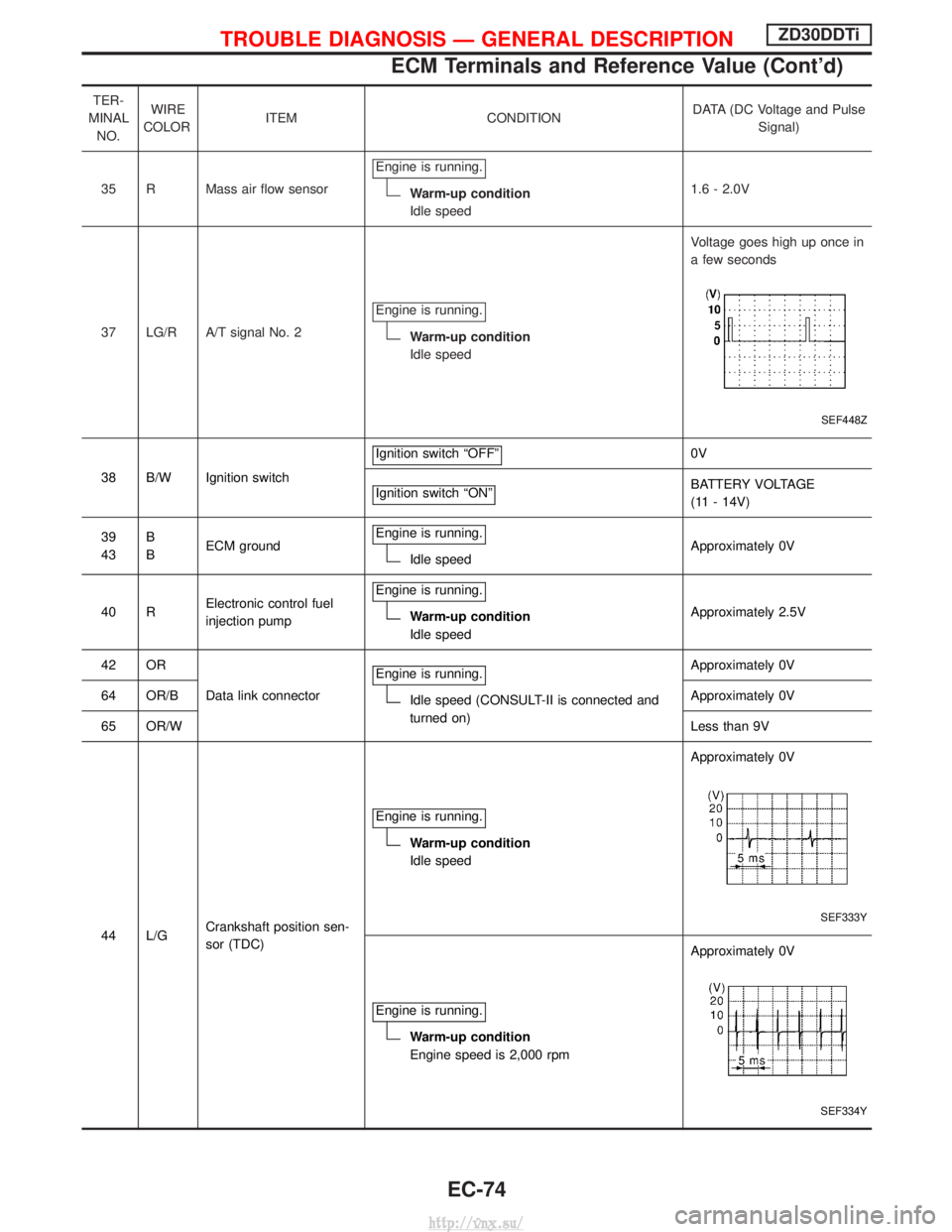
TER-
MINAL NO. WIRE
COLOR ITEM CONDITION DATA (DC Voltage and Pulse
Signal)
35 R Mass air flow sensor Engine is running.
Warm-up condition
Idle speed 1.6 - 2.0V
37 LG/R A/T signal No. 2 Engine is running.
Warm-up condition
Idle speed Voltage goes high up once in
a few seconds
SEF448Z
38 B/W Ignition switch
Ignition switch ªOFFº
0V
Ignition switch ªONº
BATTERY VOLTAGE
(11 - 14V)
39
43 B
B
ECM ground Engine is running.
Idle speed Approximately 0V
40 R Electronic control fuel
injection pump Engine is running.
Warm-up condition
Idle speed
Approximately 2.5V
42 OR Data link connector Engine is running.
Idle speed (CONSULT-II is connected and
turned on) Approximately 0V
64 OR/B Approximately 0V
65 OR/W Less than 9V
44 L/G Crankshaft position sen-
sor (TDC) Engine is running.
Warm-up condition
Idle speed
Approximately 0V
SEF333Y
Engine is running.
Warm-up condition
Engine speed is 2,000 rpmApproximately 0V
SEF334Y
TROUBLE DIAGNOSIS Ð GENERAL DESCRIPTIONZD30DDTi
ECM Terminals and Reference Value (Cont'd)
EC-74
http://vnx.su/
Page 351 of 1833
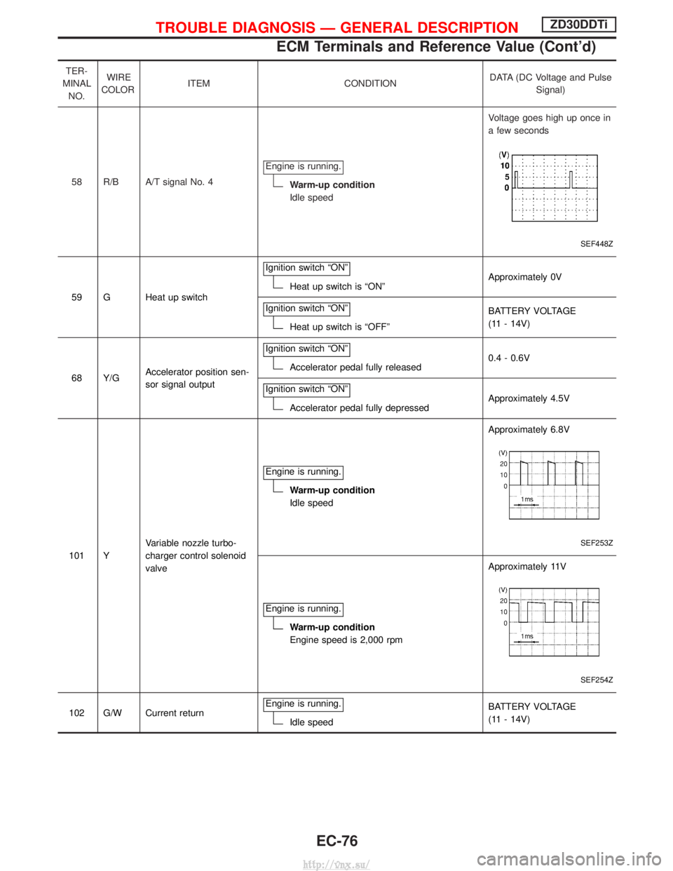
TER-
MINAL NO. WIRE
COLOR ITEM CONDITION DATA (DC Voltage and Pulse
Signal)
58 R/B A/T signal No. 4 Engine is running.
Warm-up condition
Idle speed Voltage goes high up once in
a few seconds
SEF448Z
59 G Heat up switch
Ignition switch ªONºHeat up switch is ªONº
Approximately 0V
Ignition switch ªONº
Heat up switch is ªOFFº BATTERY VOLTAGE
(11 - 14V)
68 Y/G Accelerator position sen-
sor signal output Ignition switch ªONº
Accelerator pedal fully released
0.4 - 0.6V
Ignition switch ªONº
Accelerator pedal fully depressed Approximately 4.5V
101 Y Variable nozzle turbo-
charger control solenoid
valve Engine is running.
Warm-up condition
Idle speed
Approximately 6.8V
SEF253Z
Engine is running.
Warm-up condition
Engine speed is 2,000 rpmApproximately 11V
SEF254Z
102 G/W Current return
Engine is running.Idle speed BATTERY VOLTAGE
(11 - 14V)
TROUBLE DIAGNOSIS Ð GENERAL DESCRIPTIONZD30DDTi
ECM Terminals and Reference Value (Cont'd)
EC-76
http://vnx.su/
Page 368 of 1833
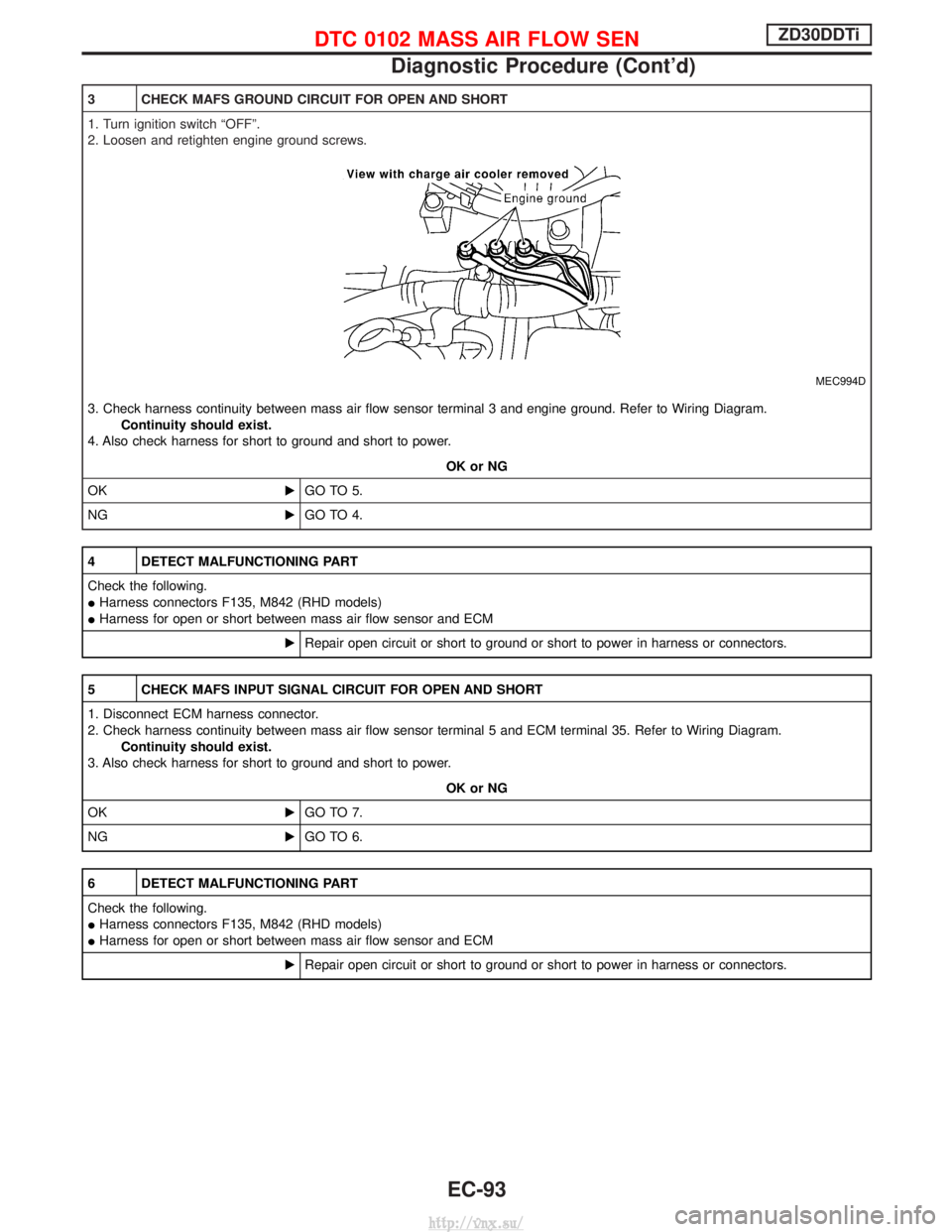
3 CHECK MAFS GROUND CIRCUIT FOR OPEN AND SHORT
1. Turn ignition switch ªOFFº.
2. Loosen and retighten engine ground screws.
MEC994D
3. Check harness continuity between mass air flow sensor terminal 3 and engine ground. Refer to Wiring Diagram.Continuity should exist.
4. Also check harness for short to ground and short to power.
OK or NG
OK EGO TO 5.
NG EGO TO 4.
4 DETECT MALFUNCTIONING PART
Check the following.
IHarness connectors F135, M842 (RHD models)
I Harness for open or short between mass air flow sensor and ECM
ERepair open circuit or short to ground or short to power in harness or connectors.
5 CHECK MAFS INPUT SIGNAL CIRCUIT FOR OPEN AND SHORT
1. Disconnect ECM harness connector.
2. Check harness continuity between mass air flow sensor terminal 5 and ECM terminal 35. Refer to Wiring Diagram.
Continuity should exist.
3. Also check harness for short to ground and short to power.
OK or NG
OK EGO TO 7.
NG EGO TO 6.
6 DETECT MALFUNCTIONING PART
Check the following.
IHarness connectors F135, M842 (RHD models)
I Harness for open or short between mass air flow sensor and ECM
ERepair open circuit or short to ground or short to power in harness or connectors.
DTC 0102 MASS AIR FLOW SENZD30DDTi
Diagnostic Procedure (Cont'd)
EC-93
http://vnx.su/