2004 NISSAN TERRANO turn signal
[x] Cancel search: turn signalPage 1739 of 1833
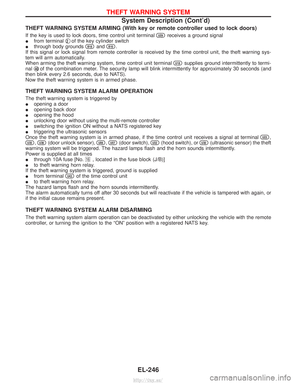
THEFT WARNING SYSTEM ARMING (With key or remote controller used to lock doors)
If the key is used to lock doors, time control unit terminalU29receives a ground signal
I from terminal q
2of the key cylinder switch
I through body grounds
B18andB10.
If this signal or lock signal from remote controller is received by the time control unit, the theft warning sys-
tem will arm automatically.
When arming the theft warning system, time control unit terminal
U18supplies ground intermittently to termi-
nal q
40of the combination meter. The security lamp will blink intermittently for approximately 30 seconds (and
then blink every 2.6 seconds, due to NATS).
Now the theft warning system is in armed phase.
THEFT WARNING SYSTEM ALARM OPERATION
The theft warning system is triggered by
I opening a door
I opening back door
I opening the hood
I unlocking door without using the multi-remote controller
I switching the ignition ON without a NATS registered key
I triggering the ultrasonic sensors
Once the theft warning system is in armed phase, if the time control unit receives a signal at terminal
U25,
U35,U36(door unlock sensor),U06,U07(door switch),U32(hood switch), orU30(ultrasonic sensor) the theft
warning system will be triggered. The hazard lamps flash and the horn sounds intermittently.
Power is supplied at all times
I through 10A fuse [No.
16, located in the fuse block (J/B)]
I to theft warning horn relay.
If the theft warning system is triggered, ground is supplied
I from terminal
U43of the time control unit
I to theft warning horn relay.
The hazard lamps flash and the horn sounds intermittently.
The alarm automatically turns off after 30 seconds but will reactivate if the vehicle is tampered with again, or
if the initial cause remains present.
THEFT WARNING SYSTEM ALARM DISARMING
The theft warning system alarm operation can be deactivated by either unlocking the vehicle with the remote
controller, or turning the ignition to the ªONº position with a registered NATS key.
THEFT WARNING SYSTEM
System Description (Cont'd)
EL-246
http://vnx.su/
Page 1767 of 1833
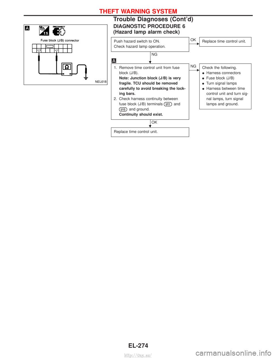
DIAGNOSTIC PROCEDURE 6
(Hazard lamp alarm check)
Push hazard switch to ON.
Check hazard lamp operation.
NG
EOKReplace time control unit.
1. Remove time control unit from fuse
block (J/B).
Note: Junction block (J/B) is very
fragile. TCU should be removed
carefully to avoid breaking the lock-
ing bars.
2. Check harness continuity between fuse block (J/B) terminals
U11and
U15and ground.
Continuity should exist.
OK
ENG Check the following.
IHarness connectors
I Fuse block (J/B)
I Turn signal lamps
I Harness between time
control unit and turn sig-
nal lamps, turn signal
lamps and ground.
Replace time control unit.
NEL618
H
H
THEFT WARNING SYSTEM
Trouble Diagnoses (Cont'd)
EL-274
http://vnx.su/
Page 1818 of 1833
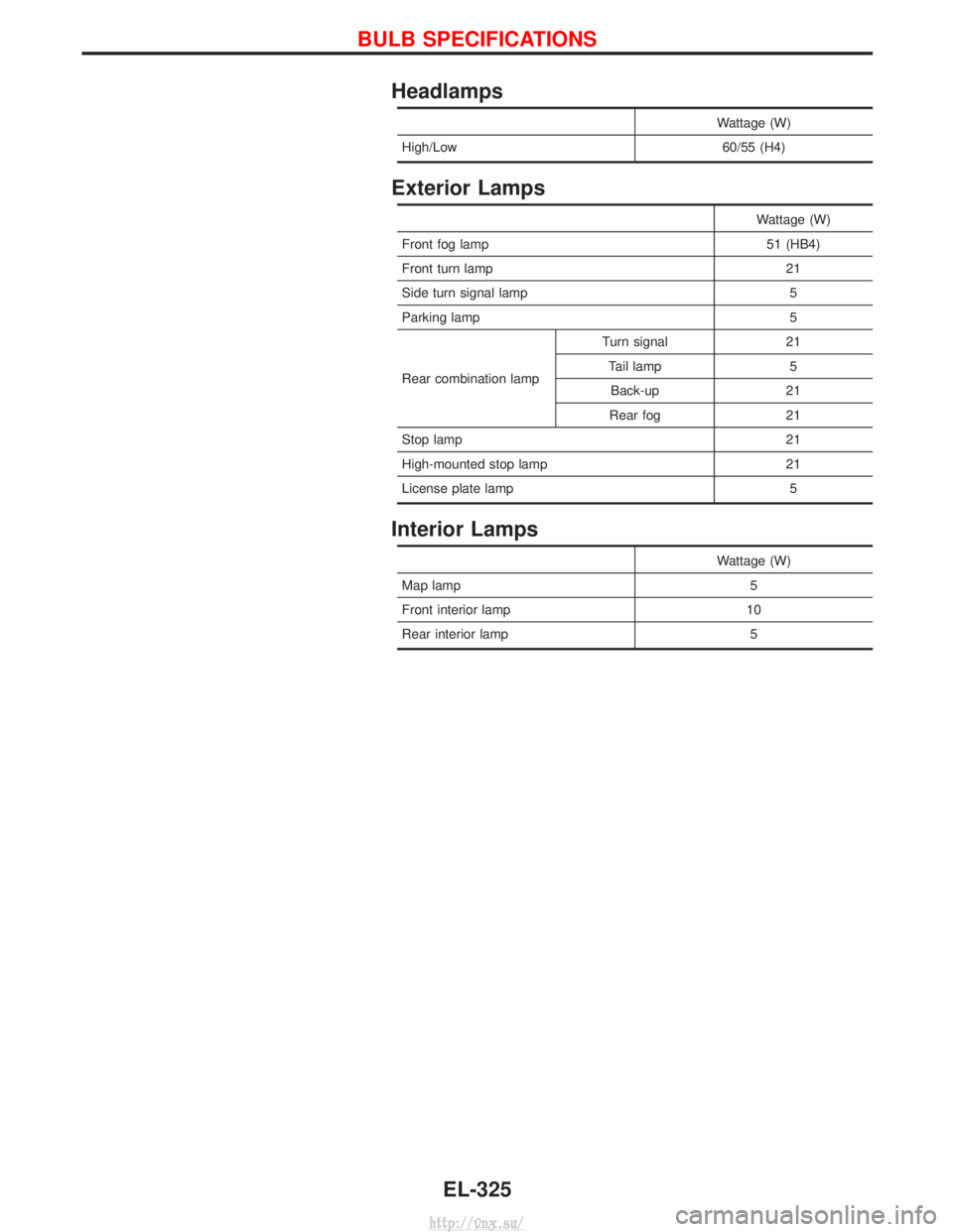
Headlamps
Wattage (W)
High/Low 60/55 (H4)
Exterior Lamps
Wattage (W)
Front fog lamp 51 (HB4)
Front turn lamp 21
Side turn signal lamp 5
Parking lamp 5
Rear combination lamp Turn signal 21
Tail lamp 5Back-up 21
Rear fog 21
Stop lamp 21
High-mounted stop lamp 21
License plate lamp 5
Interior Lamps
Wattage (W)
Map lamp 5
Front interior lamp 10
Rear interior lamp 5
BULB SPECIFICATIONS
EL-325
http://vnx.su/
Page 1820 of 1833
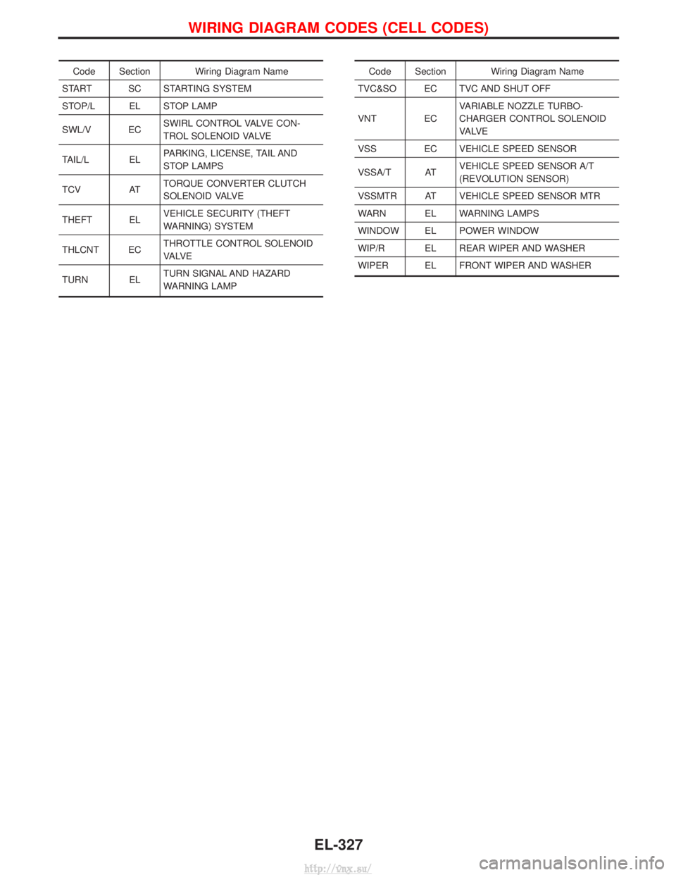
Code Section Wiring Diagram Name
START SC STARTING SYSTEM
STOP/L EL STOP LAMP
SWL/V EC SWIRL CONTROL VALVE CON-
TROL SOLENOID VALVE
TAIL/L EL PARKING, LICENSE, TAIL AND
STOP LAMPS
TCV AT TORQUE CONVERTER CLUTCH
SOLENOID VALVE
THEFT EL VEHICLE SECURITY (THEFT
WARNING) SYSTEM
THLCNT EC THROTTLE CONTROL SOLENOID
VA LV E
TURN EL TURN SIGNAL AND HAZARD
WARNING LAMPCode Section Wiring Diagram Name
TVC&SO EC TVC AND SHUT OFF
VNT EC VARIABLE NOZZLE TURBO-
CHARGER CONTROL SOLENOID
VA LV E
VSS EC VEHICLE SPEED SENSOR
VSSA/T AT VEHICLE SPEED SENSOR A/T
(REVOLUTION SENSOR)
VSSMTR AT VEHICLE SPEED SENSOR MTR
WARN EL WARNING LAMPS
WINDOW EL POWER WINDOW
WIP/R EL REAR WIPER AND WASHER
WIPER EL FRONT WIPER AND WASHER
WIRING DIAGRAM CODES (CELL CODES)
EL-327
http://vnx.su/
Page 1831 of 1833
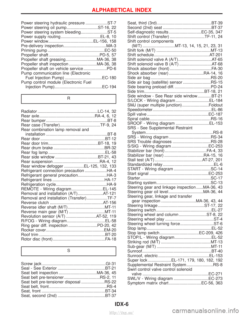
Power steering hydraulic pressure ...................ST-7
Power steering oil pump ...........................ST-16, 22
Power steering system bleeding.......................ST-5
Power supply routing ..................................EL-8, 10
Power window.......................................EL-156, 158
Pre-delivery inspection.....................................MA-3
Priming pump .................................................EC-50
Propeller shaft ............................................PD-5, 57
Propeller shaft greasing...........................MA-36, 38
Propeller shaft inspection ........................MA-36, 38
Propeller shaft on vehicle service ....................PD-6
Pump communication line (ElectronicFuel Injection Pump) ................................EC-180
Pump control module (Electronic Fuel Injection Pump).........................................EC-194
R
Radiator ....................................................LC-14, 32
Rear axle................................................RA-4, 6, 12
Rear bumper .....................................................BT-8
Rear case (Transfer)...................................TF-9, 24
Rear combination lamp removal andinstallation .....................................................BT-8
Rear door ........................................................BT-12
Rear door trim...........................................BT-18, 19
Rear drum brake ............................................BR-32
Rear fog lamp .................................................EL-58
Rear side window .....................................BT-21, 43
Rear suspension ........................................RA-4, 12
Rear window defogger .................EL-125, 132, 133
Refrigerant connection precaution ...................HA-4
Refrigerant general precaution.........................HA-3
Refrigerant lines .............................................HA-17
Refrigeration cycle............................................HA-9
REMOTE - Wiring diagram ...........................EL-145
Removal and installation (A/T)......................AT-121
Removal and installation (Transfer) ..................TF-7
Reverse clutch ..............................................AT-156
Reverse idler shaft (M/T)................................MT-11
Reverse main gear (M/T) ...............................MT-11
Revolution sensor (A/T) ..........................AT-52, 119
R/FOG - Wiring diagram .................................EL-58
Ring gear diff. inspection .........................PD-20, 42
Rocker cover ..................................................EM-20
Roof trim .........................................................BT-20
Rotor disc (front) .............................................FA-18
S
Screw jack .......................................................GI-31
Seal - See Exterior .........................................BT-21
Seat belt inspection .................................MA-36, 45
Seat belt pre-tensioner ...............................RS-2, 11
Seat belt pre-tensioner disposal ....................RS-22
Seat belt, front ..................................................RS-4
Seat, front .......................................................BT-34
Seat, second (2nd) .........................................BT-37 Seat, third (3rd) ...............................................BT-39
Second (2nd) seat ..........................................BT-37
Self-diagnostic results ............................EC-35, 347
Shift control (Transfer) ..............................TF-11, 24
Shift control components
(M/T) ............................MT-13, 14, 15, 21, 23, 31
Shift fork (M/T) ...............................................MT-13
Shift schedule................................................AT-201
Shift solenoid valve A (A/T).............................AT-65
Shift solenoid valve B (A/T) ............................AT-68
Shock absorber (front) ....................................FA-30
Shock absorber (rear) ..............................RA-14, 16
Side air bag ....................................................RS-20
Side air bag (satellite) sensor ........................RS-15
Side bearing preload diff. ...............................PD-24
Side trim....................................................BT-18, 21
Side window - See Rear side window ............BT-21
S/LOCK - Wiring diagram .............................EL-184
SMJ (super multiple junction) .......................Foldout
Speedometer...................................................EL-86
Spill valve .....................................................EC-187
Spiral cable.....................................................RS-16
SROOF - Wiring diagram .............................EL-153
SRS - See Supplemental Restraint System ..........................................................RS-8
SRS - Wiring diagram ....................................RS-34
SRS Trouble diagnoses .................................RS-28
S/SIG - Wiring diagram ................................EC-253
Stabilizer bar (front) ....................................FA-4, 33
Stabilizer bar (rear) ..................................RA-15, 16
Stall test (A/T) .........................................AT-27, 201
Standardized relay ............................................EL-6
START - Wiring diagram ................................SC-14
Start signal ...................................................EC-253
Starter .............................................................SC-17
Starting system...............................................SC-13
Steering gear and linkage inspection ......MA-36, 43
Steering gear oil level ..............................MA-36, 44
Steering gear, linkage and transfer gear inspection ..............................MA-36, 43, 44
Steering linkage ........................................ST-17, 22
Steering switch................................................EL-27
Steering wheel and column ........................ST-8, 22
Steering wheel play ..........................................ST-4
Steering wheel turning force .............................ST-6
Stop lamp ........................................................EL-52
Stop lamp switch ..................................EC-209, 426
STOP/L - Wiring diagram................................EL-52
Striking rod (M/T) ...........................................MT-13
Sub-gear (M/T) ...............................................MT-11
Sunroof............................................................BT-40
Sunroof, electric ............................................EL-153
Super lock ....................EL-171, 179, 180, 182, 192
Supplemental Restraint System .......................RS-8
Swirl control valve control solenoid valve .........................................................EC-271
SWL/V - Wiring diagram ..............................EC-273
Symptom matrix chart ............................EC-56, 363
ALPHABETICAL INDEX
IDX-6
http://vnx.su/
Page 1832 of 1833
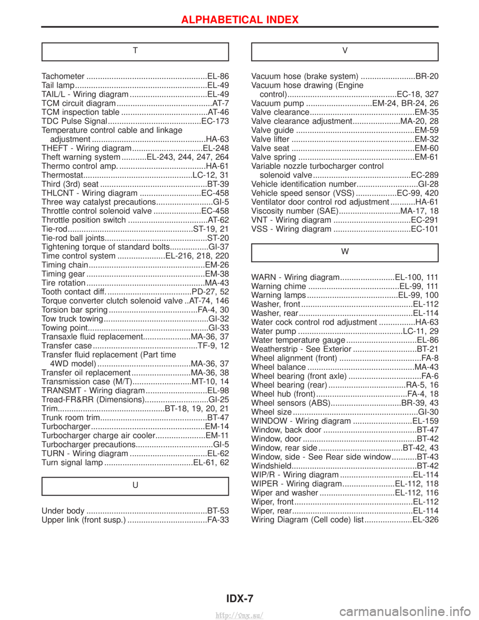
T
Tachometer .....................................................EL-86
Tail lamp ..........................................................EL-49
TAIL/L - Wiring diagram ..................................EL-49
TCM circuit diagram ..........................................AT-7
TCM inspection table ......................................AT-46
TDC Pulse Signal .........................................EC-173
Temperature control cable and linkageadjustment ..................................................HA-63
THEFT - Wiring diagram...............................EL-248
Theft warning system ...........EL-243, 244, 247, 264
Thermo control amp. ......................................HA-61
Thermostat................................................LC-12, 31
Third (3rd) seat ...............................................BT-39
THLCNT - Wiring diagram ...........................EC-458
Three way catalyst precautions.........................GI-5
Throttle control solenoid valve .....................EC-458
Throttle position switch ...................................AT-62
Tie-rod .......................................................ST-19, 21
Tie-rod ball joints.............................................ST-20
Tightening torque of standard bolts.................GI-37
Time control system .....................EL-216, 218, 220
Timing chain ...................................................EM-26
Timing gear ....................................................EM-38
Tire rotation ....................................................MA-43
Tooth contact diff. .....................................PD-27, 52
Torque converter clutch solenoid valve ..AT-74, 146
Torsion bar spring .......................................FA-4, 30
Tow truck towing ..............................................GI-32
Towing point.....................................................GI-33
Transaxle fluid replacement.....................MA-36, 37
Transfer case ..............................................TF-9, 12
Transfer fluid replacement (Part time 4WD model) .........................................MA-36, 37
Transfer oil replacement ..........................MA-36, 38
Transmission case (M/T)..........................MT-10, 14
TRANSMT - Wiring diagram ...........................EL-98
Tread-FR&RR (Dimensions)............................GI-25
Trim...............................................BT-18, 19, 20, 21
Trunk room trim...............................................BT-47
Turbocharger ..................................................EM-14
Turbocharger charge air cooler......................EM-11
Turbocharger precautions..................................GI-5
TURN - Wiring diagram ..................................EL-62
Turn signal lamp .......................................EL-61, 62
U
Under body .....................................................BT-53
Upper link (front susp.) ...................................FA-33 V
Vacuum hose (brake system) ........................BR-20
Vacuum hose drawing (Engine
control)................................................EC-18, 327
Vacuum pump .............................EM-24, BR-24, 26
Valve clearance..............................................EM-35
Valve clearance adjustment.....................MA-20, 28
Valve guide ....................................................EM-59
Valve lifter ......................................................EM-32
Valve seat ......................................................EM-60
Valve spring ...................................................EM-61
Variable nozzle turbocharger control solenoid valve ...........................................EC-289
Vehicle identification number...........................GI-28
Vehicle speed sensor (VSS) ..................EC-99, 420
Ventilator door control rod adjustment ...........HA-61
Viscosity number (SAE)...........................MA-17, 18
VNT - Wiring diagram ..................................EC-291
VSS - Wiring diagram ..................................EC-101
W
WARN - Wiring diagram........................EL-100, 111
Warning chime ........................................EL-99, 111
Warning lamps ........................................EL-99, 100
Washer, front .................................................EL-112
Washer, rear ..................................................EL-114
Water cock control rod adjustment ................HA-63
Water pump ..............................................LC-11, 29
Water temperature gauge ...............................EL-86
Weatherstrip - See Exterior ............................BT-21
Wheel alignment (front) ....................................FA-8
Wheel balance ...............................................MA-43
Wheel bearing (front axle) ................................FA-6
Wheel bearing (rear) ..................................RA-5, 16
Wheel hub (front) ........................................FA-4, 18
Wheel sensors (ABS)...............................BR-39, 43
Wheel size .......................................................GI-30
WINDOW - Wiring diagram ..........................EL-159
Window, back door .........................................BT-47
Window, door ..................................................BT-42
Window, rear side .....................................BT-42, 43
Window, side - See Rear side window ...........BT-43
Windshield.......................................................BT-42
WIP/R - Wiring diagram ................................EL-114
WIPER - Wiring diagram .......................EL-112, 118
Wiper and washer .................................EL-112, 116
Wiper, front ....................................................EL-112
Wiper, rear.....................................................EL-114
Wiring Diagram (Cell code) list .....................EL-326
ALPHABETICAL INDEX
IDX-7
http://vnx.su/