2004 NISSAN TERRANO ESP
[x] Cancel search: ESPPage 3 of 1833

FOREWORD
This manual contains maintenance and repair procedures for NISSAN
TERRANO, model R20 series.
In order to assure your safety and the efficient functioning of the vehicle,
this manual should be read thoroughly. It is especially important that the
PRECAUTIONS in the GI section be completely understood before starting
any repair task.
All information in this manual is based on the latest product information
at the time of publication. The right is reserved to make changes in speci-
fications and methods at any time without notice.
IMPORTANT SAFETY NOTICE
The proper performance of service is essential for both the safety of the
technician and the efficient functioning of the vehicle.
The service methods in this Service Manual are described in such a man-
ner that the service may be performed safely and accurately.
Service varies with the procedures used, the skills of the technician and the
tools and parts available. Accordingly, anyone using service procedures,
tools or parts which are not specifically recommended by NISSAN must
first completely satisfy himself that neither his safety nor the vehicle's
safety will be jeopardized by the service method selected.
NISSAN EUROPE S.A.S.
Service Engineering SectionParis, France
http://vnx.su/
Page 5 of 1833

Observe the following precautions to ensure safe and proper
servicing. These precautions are not described in each indi-
vidual section.
1. Do not operate the engine for an extended period of time with-out proper exhaust ventilation.
Keep the work area well ventilated and free of any inflammable
materials. Special care should be taken when handling any
inflammable or poisonous materials, such as gasoline, refriger-
ant gas, etc. When working in a pit or other enclosed area, be
sure to properly ventilate the area before working with hazard-
ous materials.
Do not smoke while working on the vehicle.
2. Before jacking up the vehicle, apply wheel chocks or other tire blocks to the wheels to prevent the vehicle from moving. After
jacking up the vehicle, support the vehicle weight with safety
stands at the points designated for proper lifting and towing
before working on the vehicle.
These operations should be done on a level surface.
3. When removing a heavy component such as the engine or transaxle/transmission, take care not to lose your balance and
drop it. Also, do not allow it to strike adjacent parts, especially
the brake tubes and master cylinder.
4. Before starting repairs which do not require battery power, always turn off the ignition switch, then disconnect the ground
cable from the battery to prevent accidental short circuit.
5. To prevent serious burns, avoid contact with hot metal parts such as the radiator, exhaust manifold, tail pipe and muffler. Do
not remove the radiator cap when the engine is hot.
SGI285
SGI231
SGI232
SGI233
PRECAUTIONS
GI-2
http://vnx.su/
Page 16 of 1833
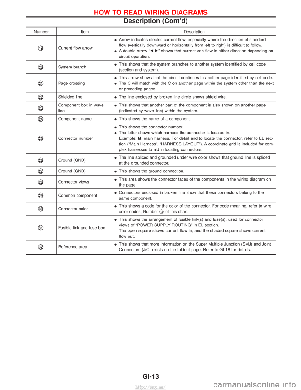
NumberItem Description
q19Current flow arrowI
Arrow indicates electric current flow, especially where the direction of standard
flow (vertically downward or horizontally from left to right) is difficult to follow.
I A double arrow ªF Ð
Eº shows that current can flow in either direction depending on
circuit operation.
q20System branch I
This shows that the system branches to another system identified by cell code
(section and system).
q21Page crossing I
This arrow shows that the circuit continues to another page identified by cell code.
I The C will match with the C on another page within the system other than the next
or preceding pages.
q22Shielded line IThe line enclosed by broken line circle shows shield wire.
q23Component box in wave
line I
This shows that another part of the component is also shown on another page
(indicated by wave line) within the system.
q24Component name IThis shows the name of a component.
q25Connector number I
This shows the connector number.
I The letter shows which harness the connector is located in.
Example: M: main harness. For detail and to locate the connector, refer to EL sec-
tion (ªMain Harnessº, ªHARNESS LAYOUTº). A coordinate grid is included for com-
plex harnesses to aid in locating connectors.
q26Ground (GND) I
The line spliced and grounded under wire color shows that ground line is spliced
at the grounded connector.
q27Ground (GND) IThis shows the ground connection.
q28Connector views I
This area shows the connector faces of the components in the wiring diagram on
the page.
q29Common component I
Connectors enclosed in broken line show that these connectors belong to the
same component.
q30Connector color I
This shows a code for the color of the connector. For code meaning, refer to wire
color codes, Number q14of this chart.
q31Fusible link and fuse box I
This shows the arrangement of fusible link(s) and fuse(s), used for connector
views of ªPOWER SUPPLY ROUTINGº in EL section.
The open square shows current flow in, and the shaded square shows current
flow out.
q32Reference area I
This shows that more information on the Super Multiple Junction (SMJ) and Joint
Connectors (J/C) exists on the foldout page. Refer to GI-18 for details.
HOW TO READ WIRING DIAGRAMS
Description (Cont'd)
GI-13
http://vnx.su/
Page 141 of 1833
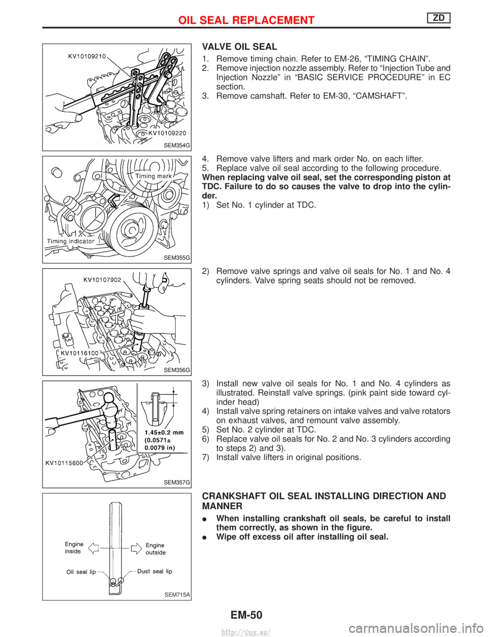
VALVE OIL SEAL
1. Remove timing chain. Refer to EM-26, ªTIMING CHAINº.
2. Remove injection nozzle assembly. Refer to ªInjection Tube andInjection Nozzleº in ªBASIC SERVICE PROCEDUREº in EC
section.
3. Remove camshaft. Refer to EM-30, ªCAMSHAFTº.
4. Remove valve lifters and mark order No. on each lifter.
5. Replace valve oil seal according to the following procedure.
When replacing valve oil seal, set the corresponding piston at
TDC. Failure to do so causes the valve to drop into the cylin-
der.
1) Set No. 1 cylinder at TDC.
2) Remove valve springs and valve oil seals for No. 1 and No. 4 cylinders. Valve spring seats should not be removed.
3) Install new valve oil seals for No. 1 and No. 4 cylinders as illustrated. Reinstall valve springs. (pink paint side toward cyl-
inder head)
4) Install valve spring retainers on intake valves and valve rotators on exhaust valves, and remount valve assembly.
5) Set No. 2 cylinder at TDC.
6) Replace valve oil seals for No. 2 and No. 3 cylinders according to steps 2) and 3).
7) Install valve lifters in original positions.
CRANKSHAFT OIL SEAL INSTALLING DIRECTION AND
MANNER
I When installing crankshaft oil seals, be careful to install
them correctly, as shown in the figure.
I Wipe off excess oil after installing oil seal.
SEM354G
SEM355G
SEM356G
SEM357G
SEM715A
OIL SEAL REPLACEMENTZD
EM-50
http://vnx.su/
Page 143 of 1833
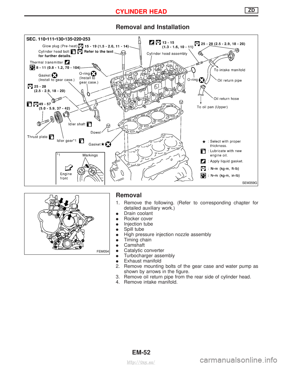
Removal and Installation
Removal
1. Remove the following. (Refer to corresponding chapter fordetailed auxiliary work.)
I Drain coolant
I Rocker cover
I Injection tube
I Spill tube
I High pressure injection nozzle assembly
I Timing chain
I Camshaft
I Catalytic converter
I Turbocharger assembly
I Exhaust manifold
2. Remove mounting bolts of the gear case and water pump as shown by arrows in the figure.
3. Remove oil return pipe from the rear side of cylinder head.
4. Remove intake manifold.
SEM359G
FEM054
CYLINDER HEADZD
EM-52
http://vnx.su/
Page 146 of 1833
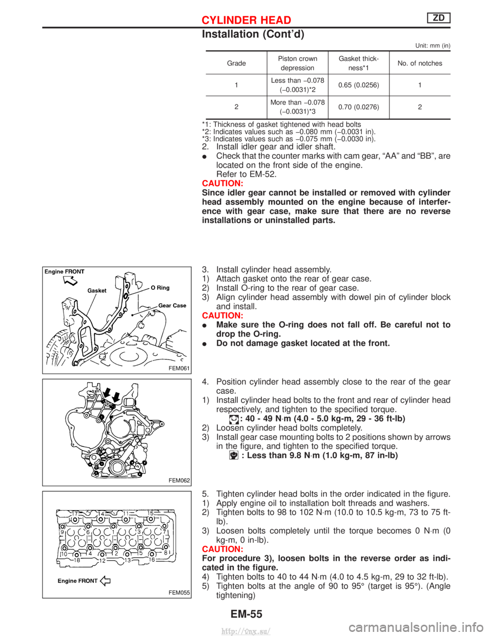
Unit: mm (in)
GradePiston crown
depression Gasket thick-
ness*1 No. of notches
1 Less than þ0.078
(þ0.0031)*2 0.65 (0.0256) 1
2 More than þ0.078
(þ0.0031)*3 0.70 (0.0276) 2
*1: Thickness of gasket tightened with head bolts
*2: Indicates values such as þ0.080 mm (þ0.0031 in).
*3: Indicates values such as þ0.075 mm (þ0.0030 in).
2. Install idler gear and idler shaft.
I
Check that the counter marks with cam gear, ªAAº and ªBBº, are
located on the front side of the engine.
Refer to EM-52.
CAUTION:
Since idler gear cannot be installed or removed with cylinder
head assembly mounted on the engine because of interfer-
ence with gear case, make sure that there are no reverse
installations or uninstalled parts.
3. Install cylinder head assembly.
1) Attach gasket onto the rear of gear case.
2) Install O-ring to the rear of gear case.
3) Align cylinder head assembly with dowel pin of cylinder block and install.
CAUTION:
I Make sure the O-ring does not fall off. Be careful not to
drop the O-ring.
I Do not damage gasket located at the front.
4. Position cylinder head assembly close to the rear of the gear case.
1) Install cylinder head bolts to the front and rear of cylinder head respectively, and tighten to the specified torque.
:40-49N ×m (4.0 - 5.0 kg-m, 29 - 36 ft-lb)
2) Loosen cylinder head bolts completely.
3) Install gear case mounting bolts to 2 positions shown by arrows in the figure, and tighten to the specified torque.
: Less than 9.8 N ×m (1.0 kg-m, 87 in-lb)
5. Tighten cylinder head bolts in the order indicated in the figure.
1) Apply engine oil to installation bolt threads and washers.
2) Tighten bolts to 98 to 102 N×m (10.0 to 10.5 kg-m, 73 to 75 ft- lb).
3) Loosen bolts completely until the torque becomes 0 N ×m(0
kg-m, 0 in-lb).
CAUTION:
For procedure 3), loosen bolts in the reverse order as indi-
cated in the figure.
4) Tighten bolts to 40 to 44 N ×m (4.0 to 4.5 kg-m, 29 to 32 ft-lb).
5) Tighten bolts at the angle of 90 to 95É (target is 95É). (Angle tightening)
FEM061
FEM062
FEM055
CYLINDER HEADZD
Installation (Cont'd)
EM-55
http://vnx.su/
Page 215 of 1833
WARNING:
a. Situate vehicle on a flat and solid surface.
b. Place chocks at front and back of rear wheels.
c. Do not remove engine until exhaust system has completelycooled off.
d. For safety during subsequent steps, the tension of wires should be slackened against the engine.
e. Be sure to hoist engine in a safe manner.
f. For engines not equipped with engine slingers, attach proper slingers and bolts described in PARTS CATALOG.
CAUTION:
I When lifting engine, be careful not to strike adjacent parts,
especially, brake lines and brake master cylinder.
I In hoisting the engine, always use engine slingers in a safe
manner.
ENGINE REMOVALTD27Ti
EM-124
http://vnx.su/
Page 229 of 1833
Assembly
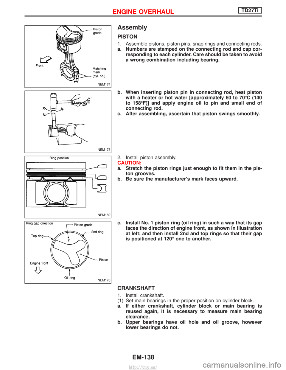
PISTON
1. Assemble pistons, piston pins, snap rings and connecting rods.
a. Numbers are stamped on the connecting rod and cap cor-responding to each cylinder. Care should be taken to avoid
a wrong combination including bearing.
b. When inserting piston pin in connecting rod, heat piston with a heater or hot water [approximately 60 to 70ÉC (140
to 158ÉF)] and apply engine oil to pin and small end of
connecting rod.
c. After assembling, ascertain that piston swings smoothly.
2. Install piston assembly.
CAUTION:
a. Stretch the piston rings just enough to fit them in the pis- ton grooves.
b. Be sure the manufacturer's mark faces upward.
c. Install No. 1 piston ring (oil ring) in such a way that its gap faces the direction of engine front, as shown in illustration
at left; and then install 2nd and top rings so that their gap
is positioned at 120É one to another.
CRANKSHAFT
1. Install crankshaft.
(1) Set main bearings in the proper position on cylinder block.
a. If either crankshaft, cylinder block or main bearing isreused again, it is necessary to measure main bearing
clearance.
b. Upper bearings have oil hole and oil groove, however lower bearings do not.
NEM174
NEM175
NEM182
NEM176
ENGINE OVERHAULTD27Ti
EM-138
http://vnx.su/