2004 NISSAN TERRANO ESP
[x] Cancel search: ESPPage 547 of 1833
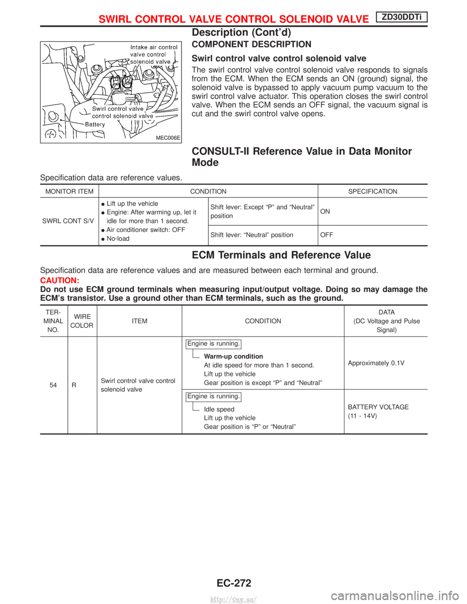
COMPONENT DESCRIPTION
Swirl control valve control solenoid valve
The swirl control valve control solenoid valve responds to signals
from the ECM. When the ECM sends an ON (ground) signal, the
solenoid valve is bypassed to apply vacuum pump vacuum to the
swirl control valve actuator. This operation closes the swirl control
valve. When the ECM sends an OFF signal, the vacuum signal is
cut and the swirl control valve opens.
CONSULT-II Reference Value in Data Monitor
Mode
Specification data are reference values.
MONITOR ITEMCONDITION SPECIFICATION
SWRL CONT S/V I
Lift up the vehicle
I Engine: After warming up, let it
idle for more than 1 second.
I Air conditioner switch: OFF
I No-load Shift lever: Except ªPº and ªNeutralº
position
ON
Shift lever: ªNeutralº position OFF
ECM Terminals and Reference Value
Specification data are reference values and are measured between each terminal and ground.
CAUTION:
Do not use ECM ground terminals when measuring input/output voltage. Doing so may damage the
ECM's transistor. Use a ground other than ECM terminals, such as the ground.
TER-
MINAL NO. WIRE
COLOR ITEM CONDITION D ATA
(DC Voltage and Pulse Signal)
54 R Swirl control valve control
solenoid valve Engine is running.
Warm-up condition
At idle speed for more than 1 second.
Lift up the vehicle
Gear position is except ªPº and ªNeutralº
Approximately 0.1V
Engine is running.
Idle speed
Lift up the vehicle
Gear position is ªPº or ªNeutralº BATTERY VOLTAGE
(11 - 14V)
MEC006E
SWIRL CONTROL VALVE CONTROL SOLENOID VALVEZD30DDTi
Description (Cont'd)
EC-272
http://vnx.su/
Page 605 of 1833
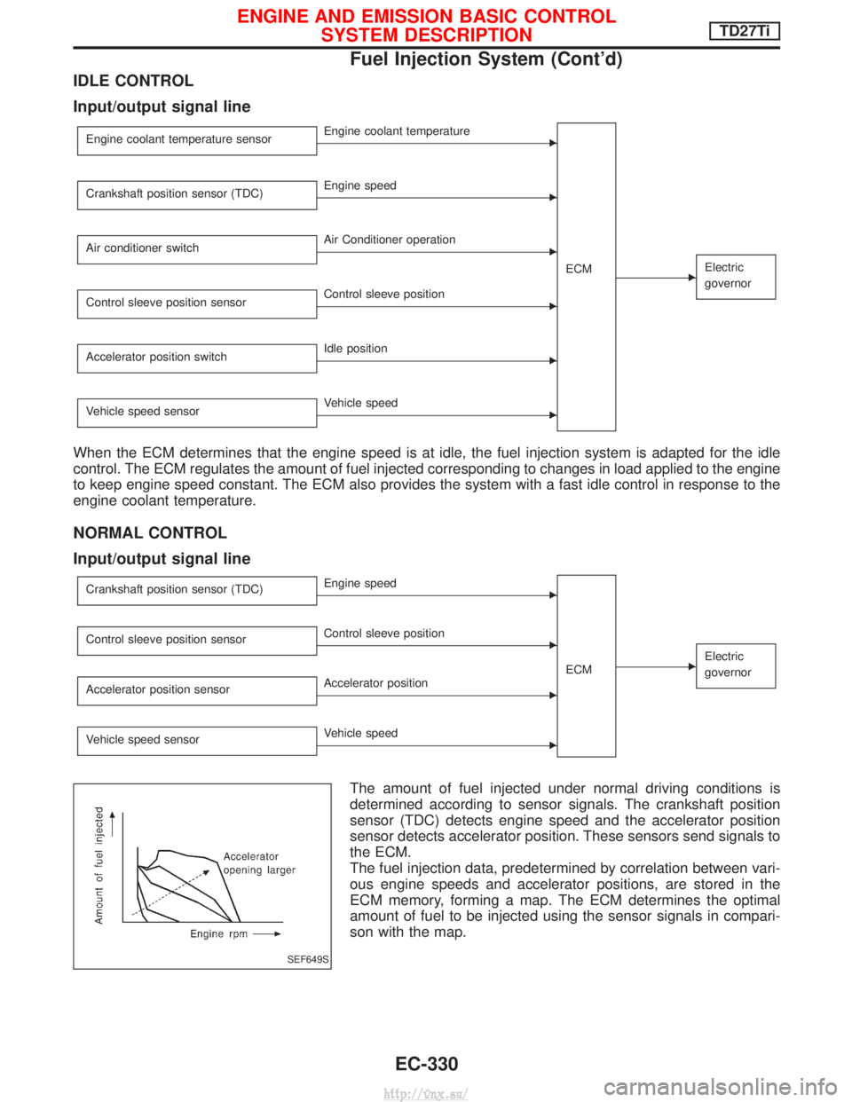
IDLE CONTROL
Input/output signal line
Engine coolant temperature sensorEEngine coolant temperatureECM
EElectric
governor
Crankshaft position sensor (TDC)EEngine speed
Air conditioner switch
EAir Conditioner operation
Control sleeve position sensor
EControl sleeve position
Accelerator position switch
EIdle position
Vehicle speed sensor
EVehicle speed
When the ECM determines that the engine speed is at idle, the fuel injection system is adapted for the idle
control. The ECM regulates the amount of fuel injected corresponding to changes in load applied to the engine
to keep engine speed constant. The ECM also provides the system with a fast idle control in response to the
engine coolant temperature.
NORMAL CONTROL
Input/output signal line
Crankshaft position sensor (TDC)EEngine speed
ECM
EElectric
governor
Control sleeve position sensorEControl sleeve position
Accelerator position sensor
EAccelerator position
Vehicle speed sensor
EVehicle speed
The amount of fuel injected under normal driving conditions is
determined according to sensor signals. The crankshaft position
sensor (TDC) detects engine speed and the accelerator position
sensor detects accelerator position. These sensors send signals to
the ECM.
The fuel injection data, predetermined by correlation between vari-
ous engine speeds and accelerator positions, are stored in the
ECM memory, forming a map. The ECM determines the optimal
amount of fuel to be injected using the sensor signals in compari-
son with the map.
SEF649S
ENGINE AND EMISSION BASIC CONTROL SYSTEM DESCRIPTIONTD27Ti
Fuel Injection System (Cont'd)
EC-330
http://vnx.su/
Page 614 of 1833
Test and Adjustment
WARNING:
When using nozzle tester, be careful not to allow diesel fuel
sprayed from nozzle to contact your hands or body, and make
sure your eyes are properly protected with goggles.
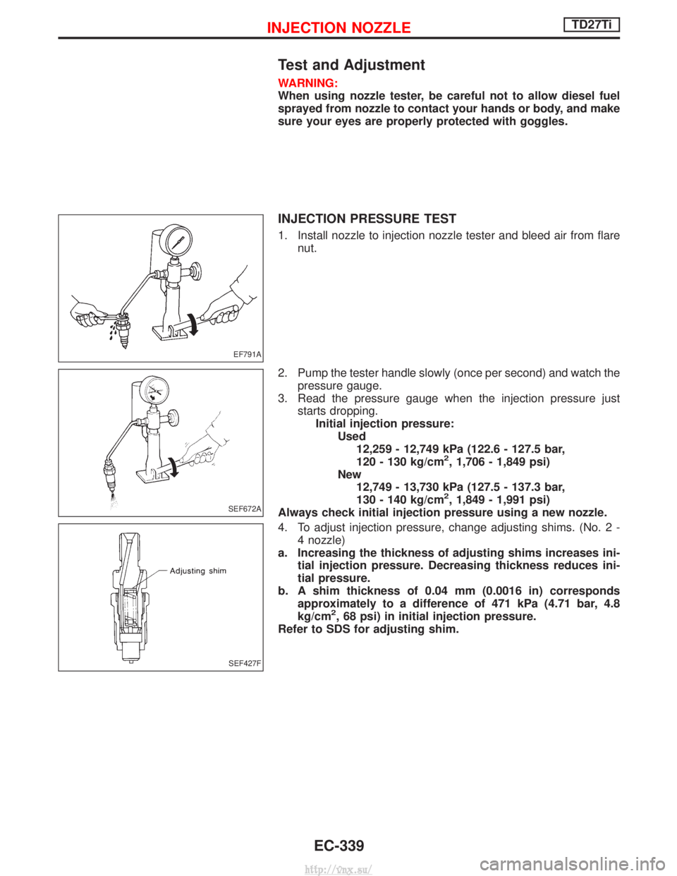
INJECTION PRESSURE TEST
1. Install nozzle to injection nozzle tester and bleed air from flarenut.
2. Pump the tester handle slowly (once per second) and watch the pressure gauge.
3. Read the pressure gauge when the injection pressure just starts dropping.Initial injection pressure: Used12,259 - 12,749 kPa (122.6 - 127.5 bar,
120 - 130 kg/cm
2, 1,706 - 1,849 psi)
New 12,749 - 13,730 kPa (127.5 - 137.3 bar,
130 - 140 kg/cm
2, 1,849 - 1,991 psi)
Always check initial injection pressure using a new nozzle.
4. To adjust injection pressure, change adjusting shims. (No. 2 - 4 nozzle)
a. Increasing the thickness of adjusting shims increases ini- tial injection pressure. Decreasing thickness reduces ini-
tial pressure.
b. A shim thickness of 0.04 mm (0.0016 in) corresponds approximately to a difference of 471 kPa (4.71 bar, 4.8
kg/cm
2, 68 psi) in initial injection pressure.
Refer to SDS for adjusting shim.
EF791A
SEF672A
SEF427F
INJECTION NOZZLETD27Ti
EC-339
http://vnx.su/
Page 630 of 1833
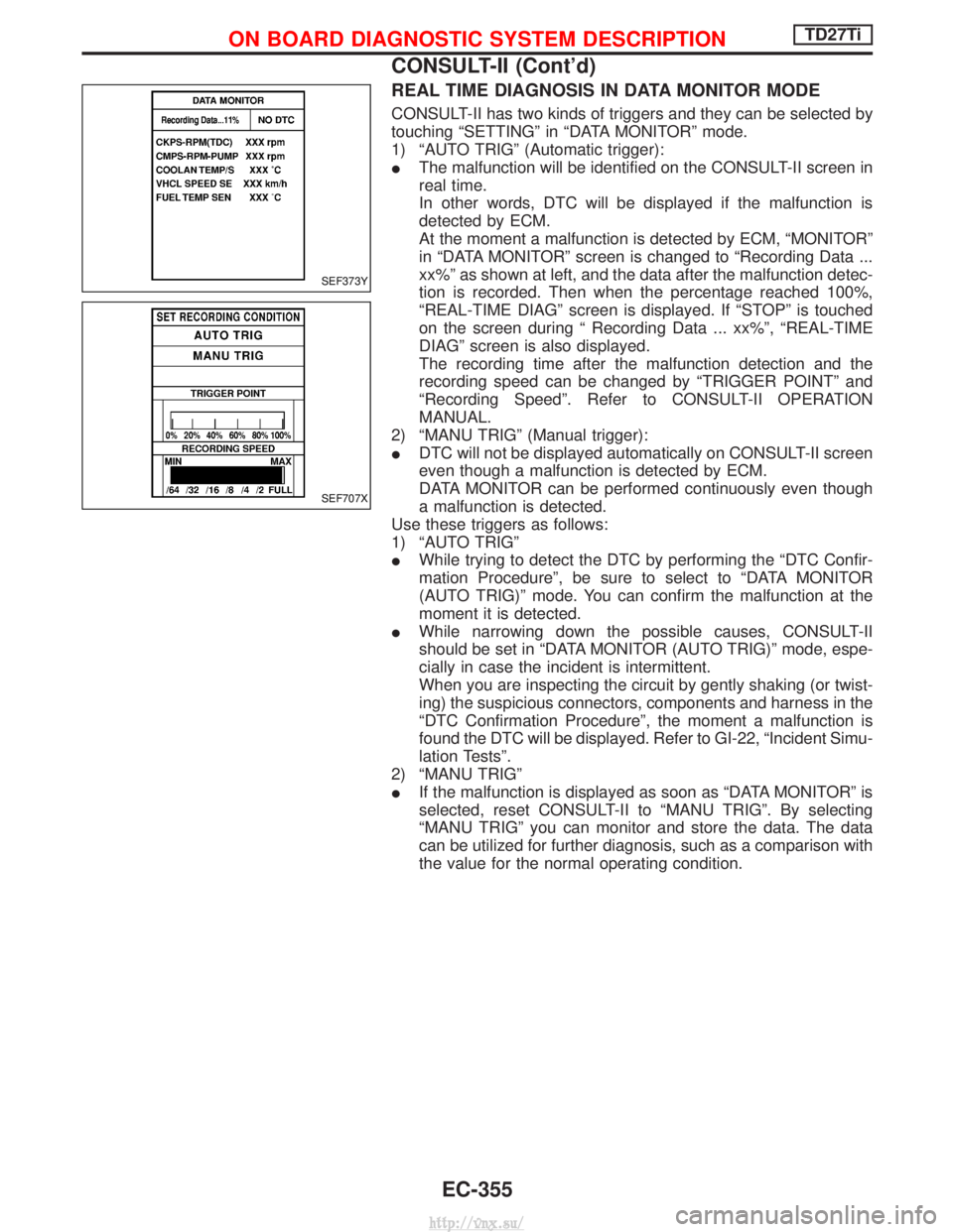
REAL TIME DIAGNOSIS IN DATA MONITOR MODE
CONSULT-II has two kinds of triggers and they can be selected by
touching ªSETTINGº in ªDATA MONITORº mode.
1) ªAUTO TRIGº (Automatic trigger):
IThe malfunction will be identified on the CONSULT-II screen in
real time.
In other words, DTC will be displayed if the malfunction is
detected by ECM.
At the moment a malfunction is detected by ECM, ªMONITORº
in ªDATA MONITORº screen is changed to ªRecording Data ...
xx%º as shown at left, and the data after the malfunction detec-
tion is recorded. Then when the percentage reached 100%,
ªREAL-TIME DIAGº screen is displayed. If ªSTOPº is touched
on the screen during ª Recording Data ... xx%º, ªREAL-TIME
DIAGº screen is also displayed.
The recording time after the malfunction detection and the
recording speed can be changed by ªTRIGGER POINTº and
ªRecording Speedº. Refer to CONSULT-II OPERATION
MANUAL.
2) ªMANU TRIGº (Manual trigger):
I DTC will not be displayed automatically on CONSULT-II screen
even though a malfunction is detected by ECM.
DATA MONITOR can be performed continuously even though
a malfunction is detected.
Use these triggers as follows:
1) ªAUTO TRIGº
I While trying to detect the DTC by performing the ªDTC Confir-
mation Procedureº, be sure to select to ªDATA MONITOR
(AUTO TRIG)º mode. You can confirm the malfunction at the
moment it is detected.
I While narrowing down the possible causes, CONSULT-II
should be set in ªDATA MONITOR (AUTO TRIG)º mode, espe-
cially in case the incident is intermittent.
When you are inspecting the circuit by gently shaking (or twist-
ing) the suspicious connectors, components and harness in the
ªDTC Confirmation Procedureº, the moment a malfunction is
found the DTC will be displayed. Refer to GI-22, ªIncident Simu-
lation Testsº.
2) ªMANU TRIGº
I If the malfunction is displayed as soon as ªDATA MONITORº is
selected, reset CONSULT-II to ªMANU TRIGº. By selecting
ªMANU TRIGº you can monitor and store the data. The data
can be utilized for further diagnosis, such as a comparison with
the value for the normal operating condition.
SEF373Y
SEF707X
ON BOARD DIAGNOSTIC SYSTEM DESCRIPTIONTD27Ti
CONSULT-II (Cont'd)
EC-355
http://vnx.su/
Page 632 of 1833
Introduction
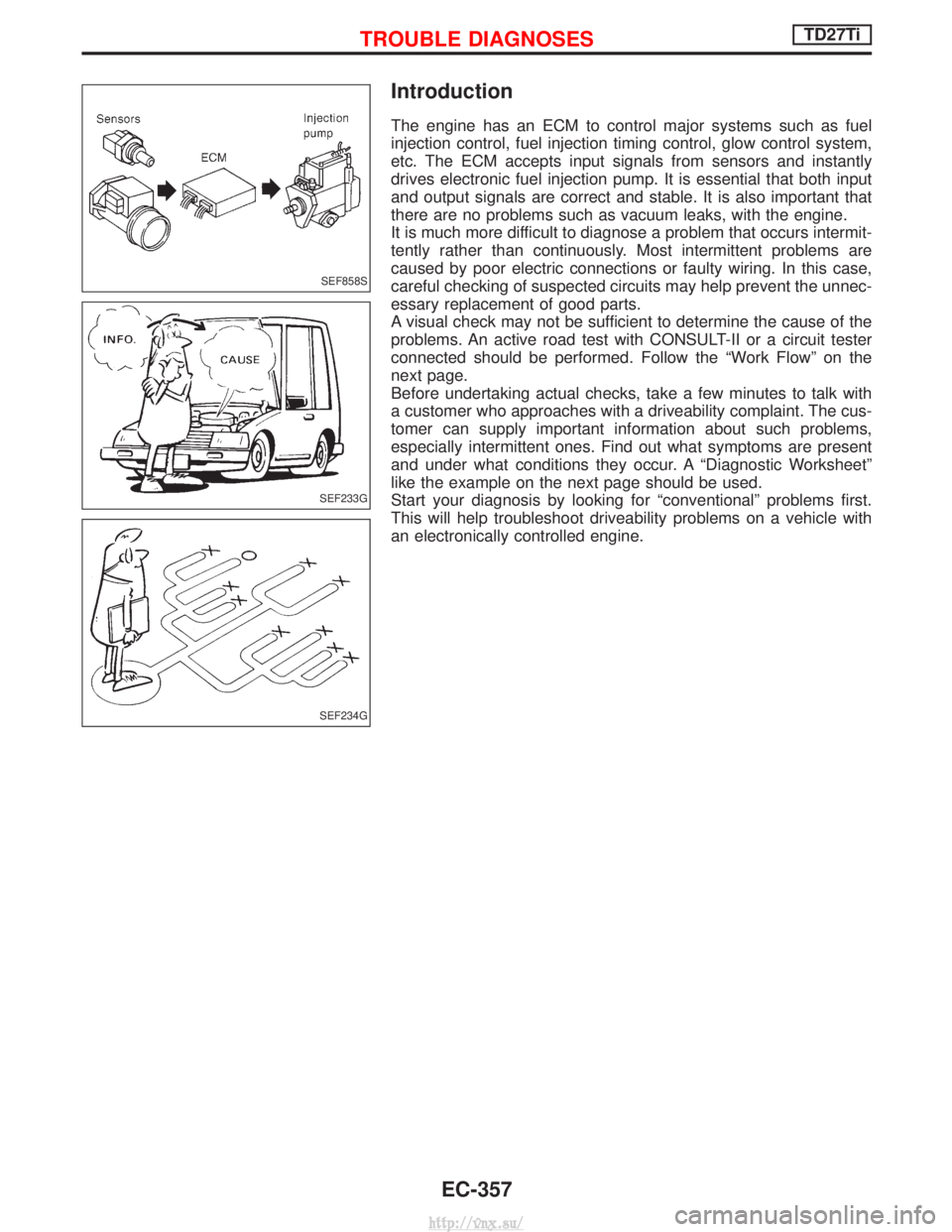
The engine has an ECM to control major systems such as fuel
injection control, fuel injection timing control, glow control system,
etc. The ECM accepts input signals from sensors and instantly
drives electronic fuel injection pump. It is essential that both input
and output signals are correct and stable. It is also important that
there are no problems such as vacuum leaks, with the engine.
It is much more difficult to diagnose a problem that occurs intermit-
tently rather than continuously. Most intermittent problems are
caused by poor electric connections or faulty wiring. In this case,
careful checking of suspected circuits may help prevent the unnec-
essary replacement of good parts.
A visual check may not be sufficient to determine the cause of the
problems. An active road test with CONSULT-II or a circuit tester
connected should be performed. Follow the ªWork Flowº on the
next page.
Before undertaking actual checks, take a few minutes to talk with
a customer who approaches with a driveability complaint. The cus-
tomer can supply important information about such problems,
especially intermittent ones. Find out what symptoms are present
and under what conditions they occur. A ªDiagnostic Worksheetº
like the example on the next page should be used.
Start your diagnosis by looking for ªconventionalº problems first.
This will help troubleshoot driveability problems on a vehicle with
an electronically controlled engine.
SEF858S
SEF233G
SEF234G
TROUBLE DIAGNOSESTD27Ti
EC-357
http://vnx.su/
Page 654 of 1833
Component Description
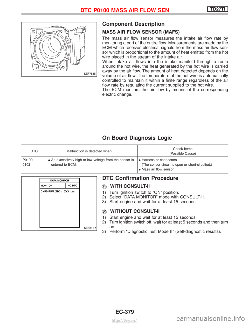
MASS AIR FLOW SENSOR (MAFS)
The mass air flow sensor measures the intake air flow rate by
monitoring a part of the entire flow. Measurements are made by the
ECM which receives electrical signals from the mass air flow sen-
sor which is proportional to the amount of heat emitted from the hot
wire placed in the stream of the intake air.
When intake air flows into the intake manifold through a route
around the hot wire, the heat generated by the hot wire is carried
away by the air flow. The amount of heat detected depends on the
volume of air flow. The temperature of the hot wire is automatically
controlled to maintain it within a finite range regardless of the air
flow rate by regulating the current supplied to the hot wire.
The ECM monitors the air flow by means of the corresponding
electric change.
On Board Diagnosis Logic
DTCMalfunction is detected when... Check Items
(Possible Cause)
P0100
0102 I
An excessively high or low voltage from the sensor is
entered to ECM. I
Harness or connectors
(The sensor circuit is open or short-circuited.)
I Mass air flow sensor
DTC Confirmation Procedure
WITH CONSULT-II
1) Turn ignition switch to ªONº position.
2) Select ªDATA MONITORº mode with CONSULT-II.
3) Start engine and wait for at least 15 seconds.
WITHOUT CONSULT-II
1) Start engine and wait for at least 15 seconds.
2) Turn ignition switch off, wait for at least 5 seconds and then turn
on.
3) Perform ªDiagnostic Test Mode IIº (Self-diagnostic results).
SEF781K
SEF817Y
DTC P0100 MASS AIR FLOW SENTD27Ti
EC-379
http://vnx.su/
Page 688 of 1833
Component Description
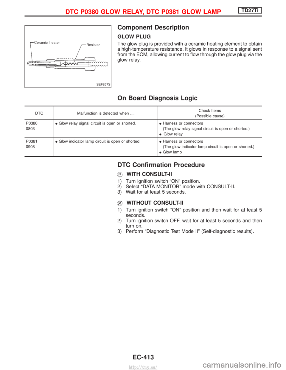
GLOW PLUG
The glow plug is provided with a ceramic heating element to obtain
a high-temperature resistance. It glows in response to a signal sent
from the ECM, allowing current to flow through the glow plug via the
glow relay.
On Board Diagnosis Logic
DTCMalfunction is detected when .... Check Items
(Possible cause)
P0380
0803 I
Glow relay signal circuit is open or shorted. IHarness or connectors
(The glow relay signal circuit is open or shorted.)
I Glow relay
P0381
0908 I
Glow indicator lamp circuit is open or shorted. IHarness or connectors
(The glow indicator lamp circuit is open or shorted.)
I Glow lamp
DTC Confirmation Procedure
WITH CONSULT-II
1) Turn ignition switch ªONº position.
2) Select ªDATA MONITORº mode with CONSULT-II.
3) Wait for at least 5 seconds.
WITHOUT CONSULT-II
1) Turn ignition switch ªONº position and then wait for at least 5
seconds.
2) Turn ignition switch OFF, wait for at least 5 seconds and then turn on.
3) Perform ªDiagnostic Test Mode IIº (Self-diagnostic results).
SEF857S
DTC P0380 GLOW RELAY, DTC P0381 GLOW LAMPTD27Ti
EC-413
http://vnx.su/
Page 708 of 1833
DTC Confirmation Procedure
WITH CONSULT-II
1) Turn ignition switch to ªONº position and select ªDATA MONI-TORº mode with CONSULT-II.
2) Start engine above 1,200 rpm.
3) Run it for 2 seconds above 1,200 rpm. Return engine speed to idle.
WITHOUT CONSULT-II
1) Start engine above 1,200 rpm.
2) Run engine for 2 seconds above 1,200 rpm. Return enginespeed to idle.
3) Turn ignition switch to ªLOCKº position, wait at least 5 seconds and then turn to ªONº position.
4) Perform ªDiagnostic Test Mode IIº (Self-diagnostic results).
NOTE:
If malfunction occurs intermittently, conduct suitable driving
pattern for 10 minutes. This makes it possible to determine
DTC.
DTC P1206 F/INJ F/B 2TD27Ti
EC-433
http://vnx.su/