2004 NISSAN TERRANO ESP
[x] Cancel search: ESPPage 231 of 1833
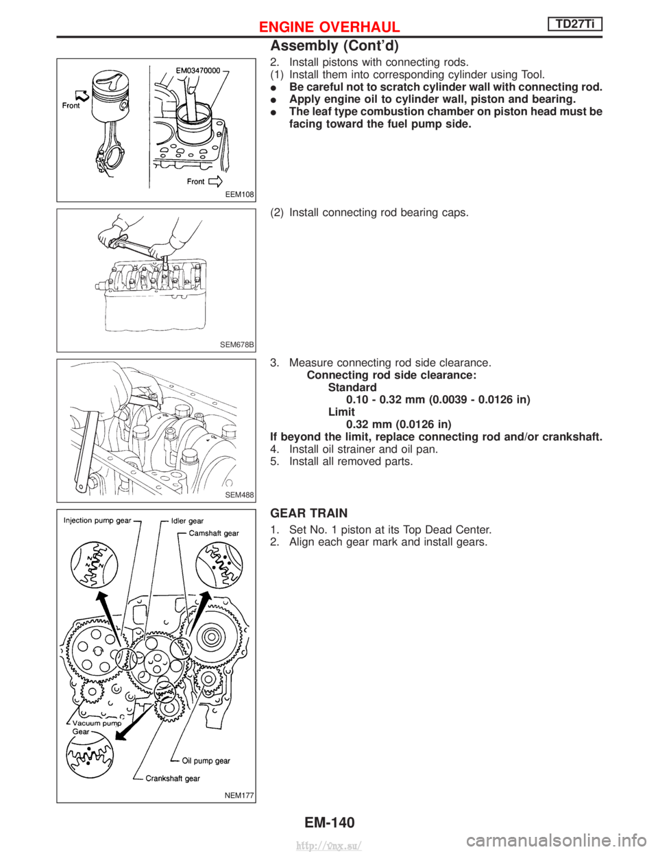
2. Install pistons with connecting rods.
(1) Install them into corresponding cylinder using Tool.
IBe careful not to scratch cylinder wall with connecting rod.
I Apply engine oil to cylinder wall, piston and bearing.
I The leaf type combustion chamber on piston head must be
facing toward the fuel pump side.
(2) Install connecting rod bearing caps.
3. Measure connecting rod side clearance. Connecting rod side clearance:Standard0.10 - 0.32 mm (0.0039 - 0.0126 in)
Limit 0.32 mm (0.0126 in)
If beyond the limit, replace connecting rod and/or crankshaft.
4. Install oil strainer and oil pan.
5. Install all removed parts.
GEAR TRAIN
1. Set No. 1 piston at its Top Dead Center.
2. Align each gear mark and install gears.
EEM108
SEM678B
SEM488
NEM177
ENGINE OVERHAULTD27Ti
Assembly (Cont'd)
EM-140
http://vnx.su/
Page 295 of 1833
Fuel Injection Control System
DESCRIPTION
System description
Three types of fuel injection control are provided to accommodate engine operating conditions; normal control,
idle control and start control. The ECM determines the appropriate fuel injection control. Under each control,
the amount of fuel injected is compensated to improve engine performance.
Pulse signals are exchanged between ECM and electronic control fuel injection pump (control unit is built-in).
The fuel injection pump control unit performs duty control on the spill valve (built into the fuel injection pump)
according to the input signals to compensate the amount of fuel injected to the preset value.
Start control
Input/output signal chart
SensorInput Signal to ECM ECM Function Actuator
Engine coolant temperature sensor Engine coolant temperature
Fuel injection con-
trol (start control)Electronic control fuel injec-
tion pump
Crankshaft position sensor (TDC)
Engine speed
Ignition switch Start signal
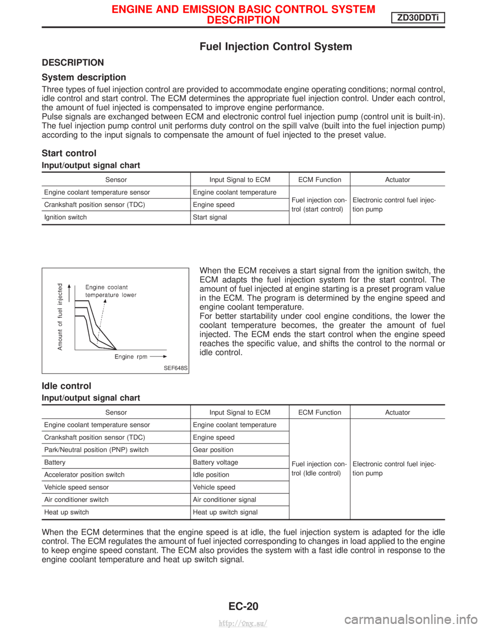
When the ECM receives a start signal from the ignition switch, the
ECM adapts the fuel injection system for the start control. The
amount of fuel injected at engine starting is a preset program value
in the ECM. The program is determined by the engine speed and
engine coolant temperature.
For better startability under cool engine conditions, the lower the
coolant temperature becomes, the greater the amount of fuel
injected. The ECM ends the start control when the engine speed
reaches the specific value, and shifts the control to the normal or
idle control.
Idle control
Input/output signal chart
SensorInput Signal to ECM ECM Function Actuator
Engine coolant temperature sensor Engine coolant temperature
Fuel injection con-
trol (Idle control)Electronic control fuel injec-
tion pump
Crankshaft position sensor (TDC)
Engine speed
Park/Neutral position (PNP) switch Gear position
Battery Battery voltage
Accelerator position switch Idle position
Vehicle speed sensor Vehicle speed
Air conditioner switch Air conditioner signal
Heat up switch Heat up switch signal
When the ECM determines that the engine speed is at idle, the fuel injection system is adapted for the idle
control. The ECM regulates the amount of fuel injected corresponding to changes in load applied to the engine
to keep engine speed constant. The ECM also provides the system with a fast idle control in response to the
engine coolant temperature and heat up switch signal.
SEF648S
ENGINE AND EMISSION BASIC CONTROL SYSTEM
DESCRIPTIONZD30DDTi
EC-20
http://vnx.su/
Page 319 of 1833

REAL TIME DIAGNOSIS IN DATA MONITOR MODE
CONSULT-II has two kinds of triggers and they can be selected by
touching ªSETTINGº in ªDATA MONITORº mode.
1) ªAUTO TRIGº (Automatic trigger):
IThe malfunction will be identified on the CONSULT-II screen in
real time.
In other words, DTC will be displayed if the malfunction is
detected by ECM.
At the moment a malfunction is detected by ECM, ªMONITORº
in ªDATA MONITORº screen is changed to ªRecording Data ...
xx%º as shown at left, and the data after the malfunction detec-
tion is recorded. Then when the percentage reached 100%,
ªREAL-TIME DIAGº screen is displayed. If ªSTOPº is touched
on the screen during ªRecording Data ... xx%º, ªREAL-TIME
DIAGº screen is also displayed.
The recording time after the malfunction detection and the
recording speed can be changed by ªTRIGGER POINTº and
ªRecording Speedº. Refer to CONSULT-II OPERATION
MANUAL.
2) ªMANU TRIGº (Manual trigger):
I DTC will not be displayed automatically on CONSULT-II screen
even though a malfunction is detected by ECM.
DATA MONITOR can be performed continuously even though
a malfunction is detected.
Use these triggers as follows:
1) ªAUTO TRIGº
I While trying to detect the DTC by performing the ªDTC Confir-
mation Procedureº, be sure to select to ªDATA MONITOR
(AUTO TRIG)º mode. You can confirm the malfunction at the
moment it is detected.
I While narrowing down the possible causes, CONSULT-II
should be set in ªDATA MONITOR (AUTO TRIG)º mode, espe-
cially in case the incident is intermittent.
When you are inspecting the circuit by gently shaking (or twist-
ing) the suspicious connectors, components and harness in the
ªDTC Confirmation Procedureº, the moment a malfunction is
found the DTC will be displayed. (Refer to GI section, ªIncident
Simulation Testsº in ªHOW TO PERFORM EFFICIENT DIAG-
NOSIS FOR AN ELECTRICAL INCIDENTº.)
2) ªMANU TRIGº
I If the malfunction is displayed as soon as ªDATA MONITORº is
selected, reset CONSULT-II to ªMANU TRIGº. By selecting
ªMANU TRIGº you can monitor and store the data. The data
can be utilized for further diagnosis, such as a comparison with
the value for the normal operating condition.
SEF373Y
SEF707X
ON BOARD DIAGNOSTIC SYSTEM DESCRIPTIONZD30DDTi
CONSULT-II (Cont'd)
EC-44
http://vnx.su/
Page 321 of 1833
Introduction
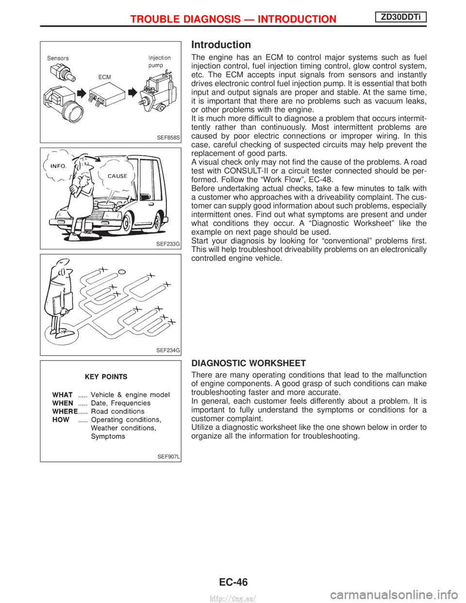
The engine has an ECM to control major systems such as fuel
injection control, fuel injection timing control, glow control system,
etc. The ECM accepts input signals from sensors and instantly
drives electronic control fuel injection pump. It is essential that both
input and output signals are proper and stable. At the same time,
it is important that there are no problems such as vacuum leaks,
or other problems with the engine.
It is much more difficult to diagnose a problem that occurs intermit-
tently rather than continuously. Most intermittent problems are
caused by poor electric connections or improper wiring. In this
case, careful checking of suspected circuits may help prevent the
replacement of good parts.
A visual check only may not find the cause of the problems. A road
test with CONSULT-II or a circuit tester connected should be per-
formed. Follow the ªWork Flowº, EC-48.
Before undertaking actual checks, take a few minutes to talk with
a customer who approaches with a driveability complaint. The cus-
tomer can supply good information about such problems, especially
intermittent ones. Find out what symptoms are present and under
what conditions they occur. A ªDiagnostic Worksheetº like the
example on next page should be used.
Start your diagnosis by looking for ªconventionalº problems first.
This will help troubleshoot driveability problems on an electronically
controlled engine vehicle.
DIAGNOSTIC WORKSHEET
There are many operating conditions that lead to the malfunction
of engine components. A good grasp of such conditions can make
troubleshooting faster and more accurate.
In general, each customer feels differently about a problem. It is
important to fully understand the symptoms or conditions for a
customer complaint.
Utilize a diagnostic worksheet like the one shown below in order to
organize all the information for troubleshooting.
SEF858S
SEF233G
SEF234G
SEF907L
TROUBLE DIAGNOSIS Ð INTRODUCTIONZD30DDTi
EC-46
http://vnx.su/
Page 325 of 1833
Basic Inspection
Precaution:
Perform Basic Inspection without electrical or mechanical
loads applied;
IShift lever is in neutral position,
I Heat up switch is OFF,
I Headlamp switch is OFF,
I Air conditioner switch is OFF,
I Rear defogger switch is OFF,
I Steering wheel is in the straight-ahead position, etc.
1 INSPECTION START
1. Check service records for any recent repairs that may indicate a related problem.
2. Check the current need for scheduled maintenance, especially for fuel filter and air cleaner filter. Refer to MA section.
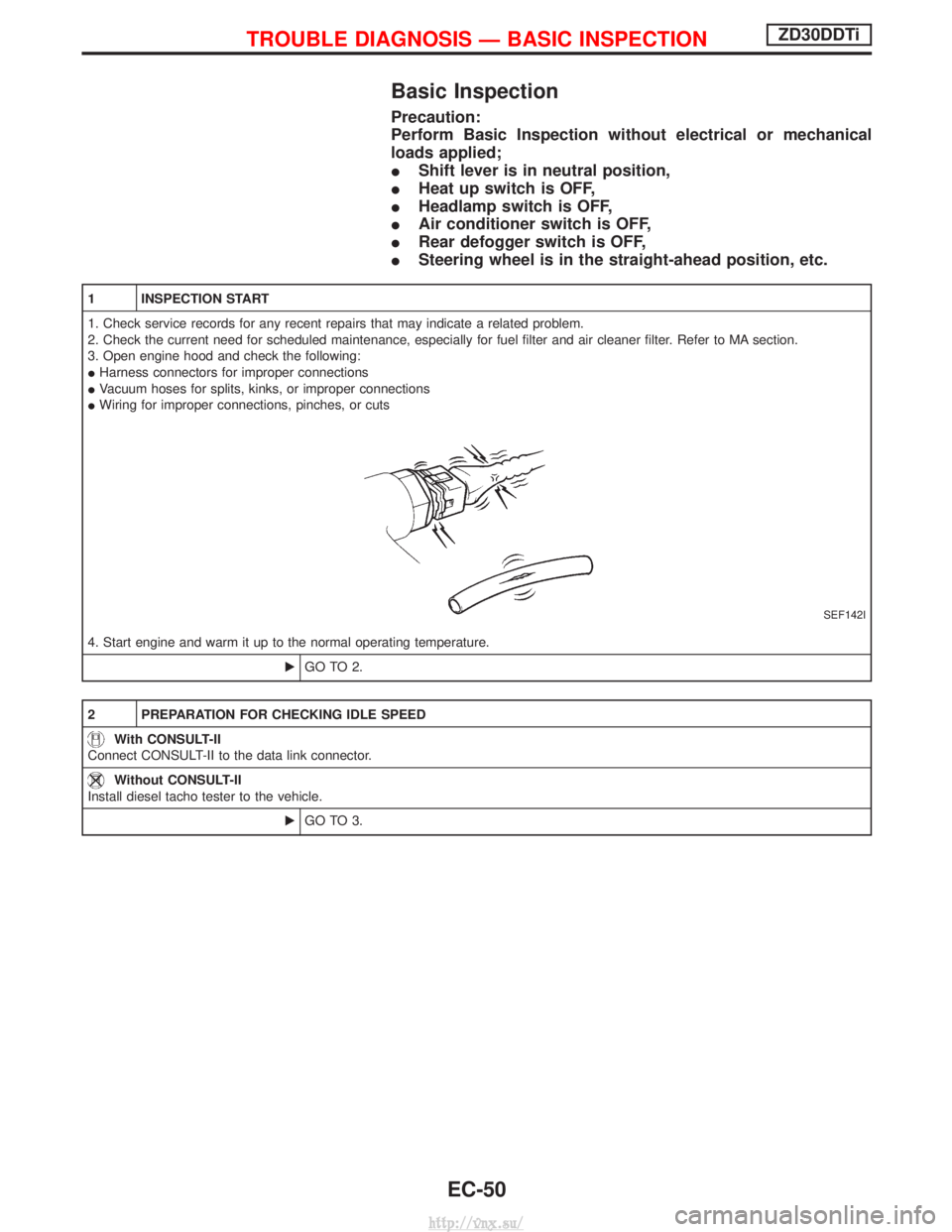
3. Open engine hood and check the following:
IHarness connectors for improper connections
I Vacuum hoses for splits, kinks, or improper connections
I Wiring for improper connections, pinches, or cuts
SEF142I
4. Start engine and warm it up to the normal operating temperature.
EGO TO 2.
2 PREPARATION FOR CHECKING IDLE SPEED
With CONSULT-II
Connect CONSULT-II to the data link connector.
Without CONSULT-II
Install diesel tacho tester to the vehicle.
EGO TO 3.
TROUBLE DIAGNOSIS Ð BASIC INSPECTIONZD30DDTi
EC-50
http://vnx.su/
Page 384 of 1833
Description
SYSTEM DESCRIPTION
SensorInput signal to ECMECM functionActuator
Vehicle speed sensor Vehicle speed
Cooling fan con-
trolCooling fan relay
Engine coolant temperature sensor Engine coolant temperature
Air conditioner switch Air conditioner ªONº signal
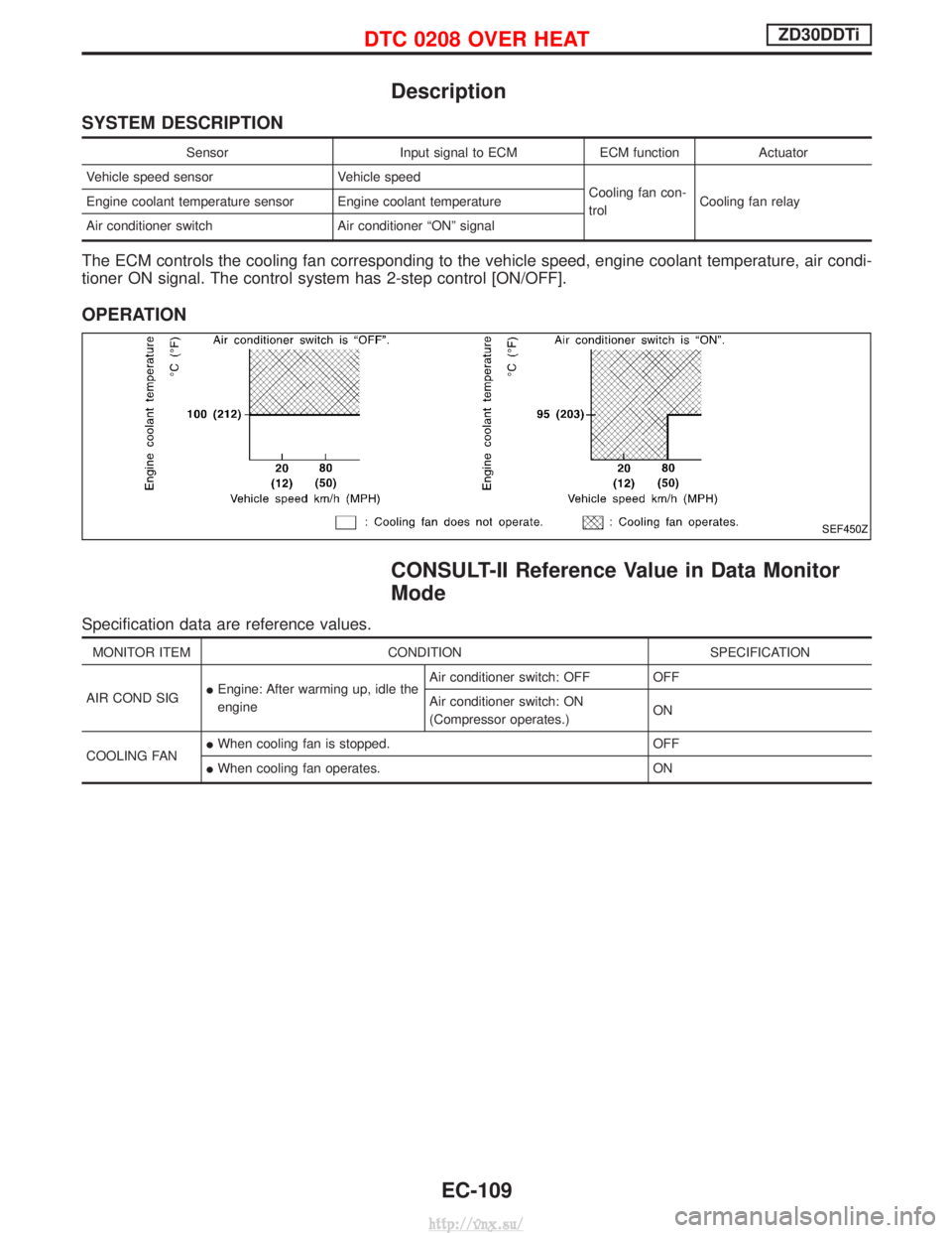
The ECM controls the cooling fan corresponding to the vehicle speed, engine coolant temperature, air condi-
tioner ON signal. The control system has 2-step control [ON/OFF].
OPERATION
CONSULT-II Reference Value in Data Monitor
Mode
Specification data are reference values.
MONITOR ITEM CONDITION SPECIFICATION
AIR COND SIG I
Engine: After warming up, idle the
engine Air conditioner switch: OFF OFF
Air conditioner switch: ON
(Compressor operates.)
ON
COOLING FAN I
When cooling fan is stopped. OFF
I When cooling fan operates. ON
SEF450Z
DTC 0208 OVER HEATZD30DDTi
EC-109
http://vnx.su/
Page 502 of 1833
Description
SYSTEM DESCRIPTION
SensorInput Signal to ECMECM FunctionActuator
Electronic controlled fuel injection pump Fuel injection signal
EGR volume
controlEGR volume control valve
Crankshaft position sensor (TDC) Engine speed
Vehicle speed sensor
Vehicle speed
Engine coolant temperature sensor Engine coolant temperature
Ignition switch Start signal
Throttle position sensor Throttle position
Battery Battery voltage
Mass air flow sensor Amount of intake air
Air conditioner switch Air conditioner operation
Electrical load Electrical load signal
PNP switch Park/Neutral position signal
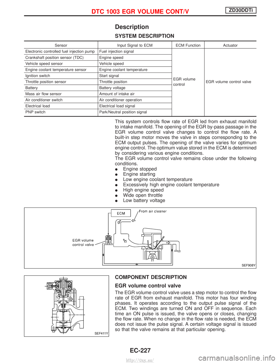
This system controls flow rate of EGR led from exhaust manifold
to intake manifold. The opening of the EGR by-pass passage in the
EGR volume control valve changes to control the flow rate. A
built-in step motor moves the valve in steps corresponding to the
ECM output pulses. The opening of the valve varies for optimum
engine control. The optimum value stored in the ECM is determined
by considering various engine conditions.
The EGR volume control valve remains close under the following
conditions.
IEngine stopped
I Engine starting
I Low engine coolant temperature
I Excessively high engine coolant temperature
I High engine speed
I Wide open throttle
I Low battery voltage
COMPONENT DESCRIPTION
EGR volume control valve
The EGR volume control valve uses a step motor to control the flow
rate of EGR from exhaust manifold. This motor has four winding
phases. It operates according to the output pulse signal of the
ECM. Two windings are turned ON and OFF in sequence. Each
time an ON pulse is issued, the valve opens or closes, changing
the flow rate. When no change in the flow rate is needed, the ECM
does not issue the pulse signal. A certain voltage signal is issued
so that the valve remains at that particular opening.
SEF908Y
SEF411Y
DTC 1003 EGR VOLUME CONT/VZD30DDTi
EC-227
http://vnx.su/
Page 519 of 1833

Description
SYSTEM DESCRIPTION
Sensor Input Signal to ECMECM
Function Actuator
Crankshaft position
sensor (TDC) Engine speed
Glow
control Glow lamp,
Glow relay "
Glow plugs
Engine coolant tem-
perature sensor Engine coolant tem-
perature
When engine coolant temperature is more than approximately 75ÉC
(167ÉF), the glow relay turns off, inactivating the quick-glow control
until coolant temperature drops below approximately 55ÉC (131ÉF).
When coolant temperature is lower than approximately 75ÉC
(167ÉF):
I
Ignition switch ON
After ignition switch has turned to ON, the glow relay turns ON
for a certain period of time in relation to engine coolant
temperature, allowing current to flow through glow plug.
I Cranking
The glow relay turns ON, allowing current to flow through glow
plug.
I Starting
After engine has started, current continues to flow through glow
plug (after-glow mode) for a certain period in relation to engine
coolant temperature.
When engine speed exceeds approximately 4,800 rpm, current
flow through glow plug is interrupted.
The glow indicator lamp turns ON for a certain period of time in
relation to engine coolant temperature at the time glow relay is
turned ON.
COMPONENT DESCRIPTION
Glow plug
I The glow plug is provided with a ceramic heating element to
obtain a high-temperature resistance. It glows in response to a
signal sent from the ECM, allowing current to flow through the
glow plug via the glow relay.
I This engine uses two types of glow plugs.
Type A has a blue or yellow paint mark.
Type B has no paint mark.
The location of the paint mark is shown in the figure.
WARNING:
Do not use two types of glow plugs at the same time.
SEF376Y
SEF280Z
GLOW CONTROL SYSTEMZD30DDTi
EC-244
http://vnx.su/