2004 NISSAN TERRANO ESP
[x] Cancel search: ESPPage 716 of 1833
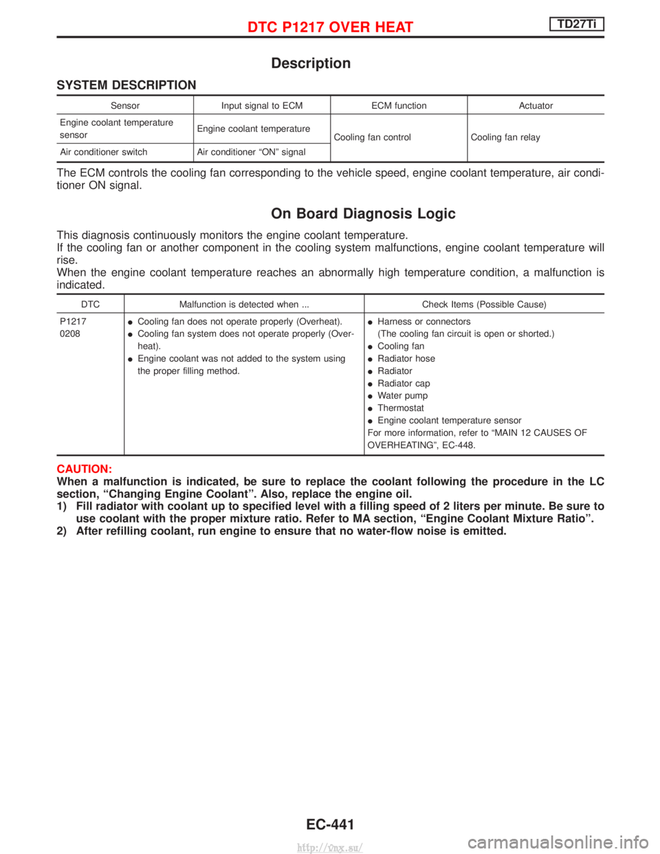
Description
SYSTEM DESCRIPTION
SensorInput signal to ECM ECM functionActuator
Engine coolant temperature
sensor Engine coolant temperature
Cooling fan control Cooling fan relay
Air conditioner switch Air conditioner ªONº signal
The ECM controls the cooling fan corresponding to the vehicle speed, engine coolant temperature, air condi-
tioner ON signal.
On Board Diagnosis Logic
This diagnosis continuously monitors the engine coolant temperature.
If the cooling fan or another component in the cooling system malfunctions, engine coolant temperature will
rise.
When the engine coolant temperature reaches an abnormally high temperature condition, a malfunction is
indicated.
DTC Malfunction is detected when ... Check Items (Possible Cause)
P1217
0208 I
Cooling fan does not operate properly (Overheat).
I Cooling fan system does not operate properly (Over-
heat).
I Engine coolant was not added to the system using
the proper filling method. I
Harness or connectors
(The cooling fan circuit is open or shorted.)
I Cooling fan
I Radiator hose
I Radiator
I Radiator cap
I Water pump
I Thermostat
I Engine coolant temperature sensor
For more information, refer to ªMAIN 12 CAUSES OF
OVERHEATINGº, EC-448.
CAUTION:
When a malfunction is indicated, be sure to replace the coolant following the procedure in the LC
section, ªChanging Engine Coolantº. Also, replace the engine oil.
1) Fill radiator with coolant up to specified level with a filling speed of 2 liters per minute. Be sure to use coolant with the proper mixture ratio. Refer to MA section, ªEngine Coolant Mixture Ratioº.
2) After refilling coolant, run engine to ensure that no water-flow noise is emitted.
DTC P1217 OVER HEATTD27Ti
EC-441
http://vnx.su/
Page 786 of 1833
IRaise the unit with a hoist.
I Position the transmission assembly on a portable jack and
secure it with a suitable tool.
Lift the assembly until the gearbox input shaft faces its hous-
ing.
Move the assembly towards the engine. The assembly must be
rotated slightly so that the starter motor housing clears the
projection on the companion floor. Insert input shaft into its
housing (slightly raising the rear of the transfer box may facili-
tate the introduction of the shaft into its housing).
I Tighten the screws securing the gearbox to the engine.
:39-49N ×m (4.0 - 5.0 kg-m, 29 - 36 ft-lb)
I Connect the electrical wiring. Secure with the respective clips.
I Fit the RPM-sensor to the transmission upper side.
I Fit the exhaust pipe support bracket to the transfer box.
:13-16N ×m (1.3 - 1.6 kg-m ,9-12ft-lb)
I Fit the starter motor. Secure the earth wire to the starter motor
lower screw.
:31-41N ×m (3.2 - 4.2 kg-m, 23 - 30 ft-lb)
I Fit the clutch slave cylinder.
:30-40N ×m (3.1 - 4.1 kg-m, 22 - 30 ft-lb)
I Install fourth crossmember (Note the ªfrontº mark).
Crossmember fixing bolts to chassis:
:41-52N ×m (4.2 - 5.3 kg-m, 30 - 38 ft-lb)
Crossmember fixing bolts to transmission:
:68-87N ×m (6.9 - 8.9 kg-m, 50 - 64 ft-lb)
I Take away the portable jack holding boxes assembly.
I Install fifth crossmember.
:59-78N ×m (6.0 - 8.0 kg-m, 43 - 58 ft-lb)
I Install third crossmember.
: Screws: 41 - 52 N ×m (4.2 - 5.3 kg-m,
30 - 38 ft-lb)
Nuts: 68 - 87 N ×m (6.9 - 8.9 kg-m,
50 - 64 ft-lb)
I Install torsion bar springs. Ð Refer to FA section.
I Install front and rear propeller shafts. Ð Refer to PD section.
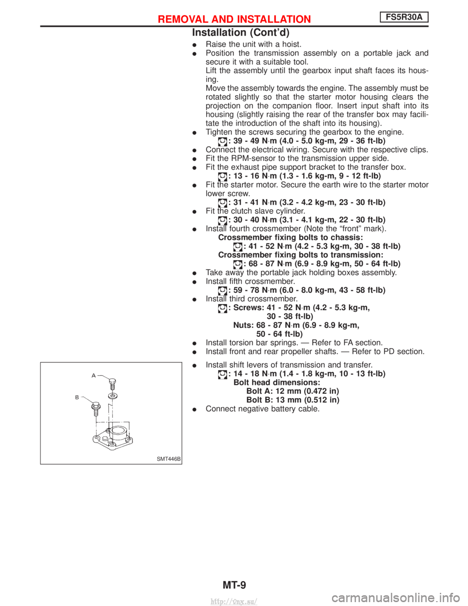
I Install shift levers of transmission and transfer.
:14-18N ×m (1.4 - 1.8 kg-m, 10 - 13 ft-lb)
Bolt head dimensions: Bolt A: 12 mm (0.472 in)
Bolt B: 13 mm (0.512 in)
I Connect negative battery cable.
SMT446B
REMOVAL AND INSTALLATIONFS5R30A
Installation (Cont'd)
MT-9
http://vnx.su/
Page 826 of 1833
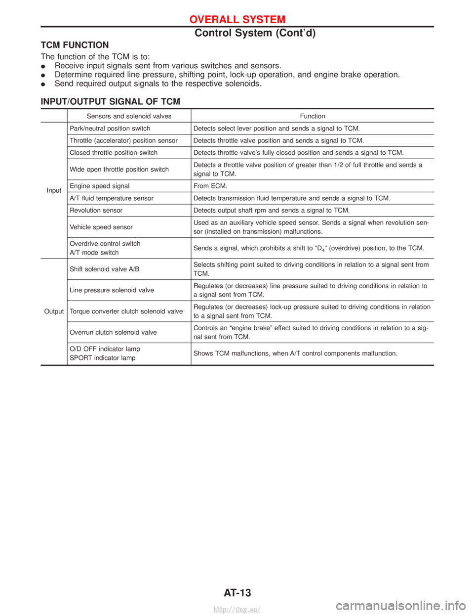
TCM FUNCTION
The function of the TCM is to:
IReceive input signals sent from various switches and sensors.
I Determine required line pressure, shifting point, lock-up operation, and engine brake operation.
I Send required output signals to the respective solenoids.
INPUT/OUTPUT SIGNAL OF TCM
Sensors and solenoid valves Function
Input Park/neutral position switch
Detects select lever position and sends a signal to TCM.
Throttle (accelerator) position sensor Detects throttle valve position and sends a signal to TCM.
Closed throttle position switch Detects throttle valve's fully-closed position and sends a signal to TCM.
Wide open throttle position switch Detects a throttle valve position of greater than 1/2 of full throttle and sends a
signal to TCM.
Engine speed signal From ECM.
A/T fluid temperature sensor Detects transmission fluid temperature and sends a signal to TCM.
Revolution sensor Detects output shaft rpm and sends a signal to TCM.
Vehicle speed sensor Used as an auxiliary vehicle speed sensor. Sends a signal when revolution sen-
sor (installed on transmission) malfunctions.
Overdrive control switch
A/T mode switch Sends a signal, which prohibits a shift to ªD
4º (overdrive) position, to the TCM.
Output Shift solenoid valve A/B
Selects shifting point suited to driving conditions in relation to a signal sent from
TCM.
Line pressure solenoid valve Regulates (or decreases) line pressure suited to driving conditions in relation to
a signal sent from TCM.
Torque converter clutch solenoid valve Regulates (or decreases) lock-up pressure suited to driving conditions in relation
to a signal sent from TCM.
Overrun clutch solenoid valve Controls an ªengine brakeº effect suited to driving conditions in relation to a sig-
nal sent from TCM.
O/D OFF indicator lamp
SPORT indicator lamp Shows TCM malfunctions, when A/T control components malfunction.
OVERALL SYSTEM
Control System (Cont'd)
AT-13
http://vnx.su/
Page 835 of 1833
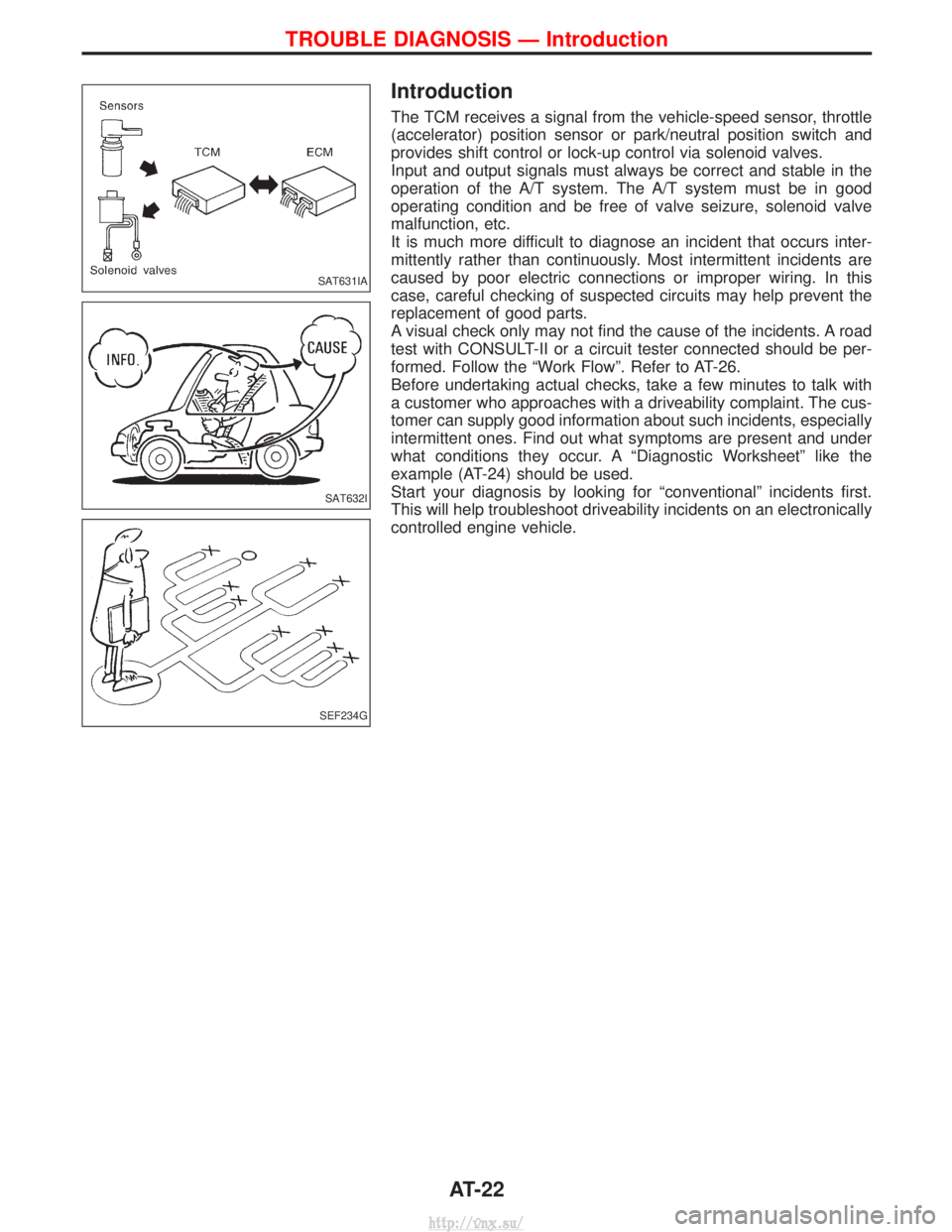
Introduction
The TCM receives a signal from the vehicle-speed sensor, throttle
(accelerator) position sensor or park/neutral position switch and
provides shift control or lock-up control via solenoid valves.
Input and output signals must always be correct and stable in the
operation of the A/T system. The A/T system must be in good
operating condition and be free of valve seizure, solenoid valve
malfunction, etc.
It is much more difficult to diagnose an incident that occurs inter-
mittently rather than continuously. Most intermittent incidents are
caused by poor electric connections or improper wiring. In this
case, careful checking of suspected circuits may help prevent the
replacement of good parts.
A visual check only may not find the cause of the incidents. A road
test with CONSULT-II or a circuit tester connected should be per-
formed. Follow the ªWork Flowº. Refer to AT-26.
Before undertaking actual checks, take a few minutes to talk with
a customer who approaches with a driveability complaint. The cus-
tomer can supply good information about such incidents, especially
intermittent ones. Find out what symptoms are present and under
what conditions they occur. A ªDiagnostic Worksheetº like the
example (AT-24) should be used.
Start your diagnosis by looking for ªconventionalº incidents first.
This will help troubleshoot driveability incidents on an electronically
controlled engine vehicle.
SAT631IA
SAT632I
SEF234G
TROUBLE DIAGNOSIS Ð Introduction
AT-22
http://vnx.su/
Page 843 of 1833
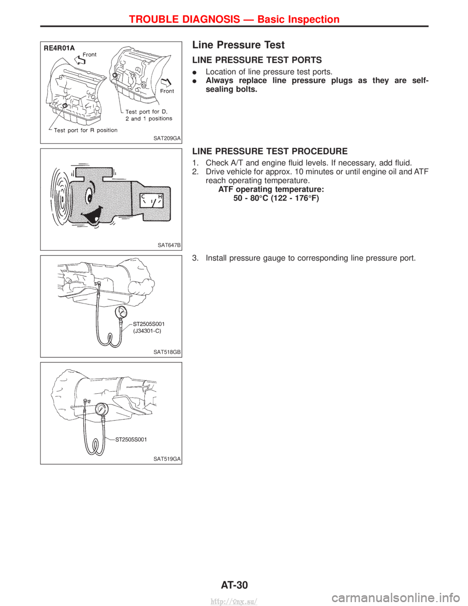
Line Pressure Test
LINE PRESSURE TEST PORTS
ILocation of line pressure test ports.
I Always replace line pressure plugs as they are self-
sealing bolts.
LINE PRESSURE TEST PROCEDURE
1. Check A/T and engine fluid levels. If necessary, add fluid.
2. Drive vehicle for approx. 10 minutes or until engine oil and ATF
reach operating temperature.ATF operating temperature: 50 - 80ÉC (122 - 176ÉF)
3. Install pressure gauge to corresponding line pressure port.
SAT209GA
SAT647B
SAT518GB
SAT519GA
TROUBLE DIAGNOSIS Ð Basic Inspection
AT-30
http://vnx.su/
Page 861 of 1833
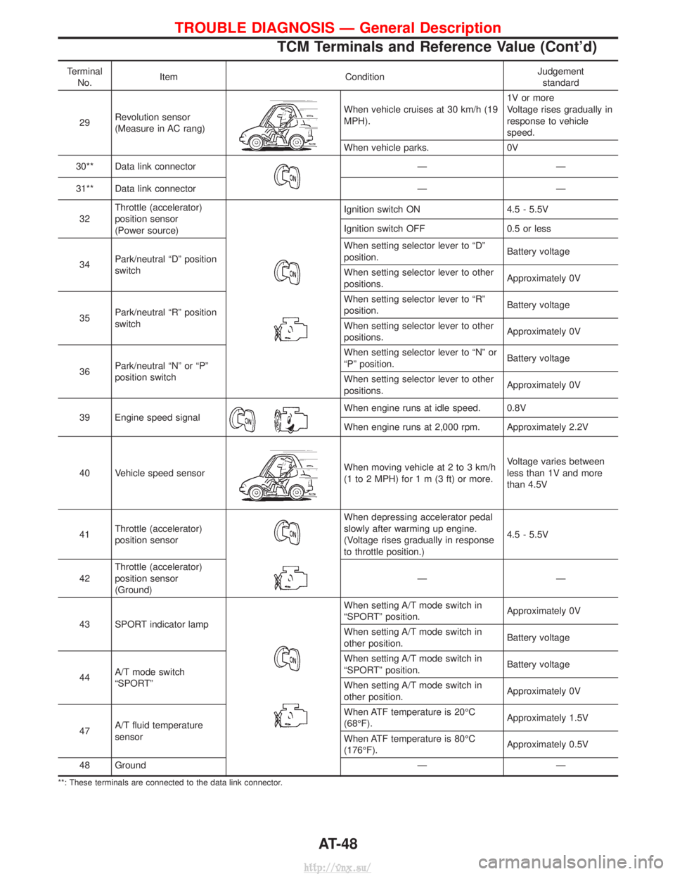
TerminalNo. Item Condition Judgement
standard
29 Revolution sensor
(Measure in AC rang)
When vehicle cruises at 30 km/h (19
MPH). 1V or more
Voltage rises gradually in
response to vehicle
speed.
When vehicle parks. 0V
30** Data link connector
ÐÐ
31** Data link connector Ð Ð
32 Throttle (accelerator)
position sensor
(Power source)
Ignition switch ON
4.5 - 5.5V
Ignition switch OFF 0.5 or less
34 Park/neutral ªDº position
switch When setting selector lever to ªDº
position.
Battery voltage
When setting selector lever to other
positions. Approximately 0V
35 Park/neutral ªRº position
switch When setting selector lever to ªRº
position.
Battery voltage
When setting selector lever to other
positions. Approximately 0V
36 Park/neutral ªNº or ªPº
position switch When setting selector lever to ªNº or
ªPº position.
Battery voltage
When setting selector lever to other
positions. Approximately 0V
39 Engine speed signal
When engine runs at idle speed. 0.8V
When engine runs at 2,000 rpm. Approximately 2.2V
40 Vehicle speed sensor
When moving vehicle at 2 to 3 km/h
(1 to 2 MPH) for1m(3ft)or more.Voltage varies between
less than 1V and more
than 4.5V
41 Throttle (accelerator)
position sensor
When depressing accelerator pedal
slowly after warming up engine.
(Voltage rises gradually in response
to throttle position.) 4.5 - 5.5V
42 Throttle (accelerator)
position sensor
(Ground) ÐÐ
43 SPORT indicator lamp
When setting A/T mode switch in
ªSPORTº position. Approximately 0V
When setting A/T mode switch in
other position. Battery voltage
44 A/T mode switch
ªSPORTº When setting A/T mode switch in
ªSPORTº position.
Battery voltage
When setting A/T mode switch in
other position. Approximately 0V
47 A/T fluid temperature
sensor When ATF temperature is 20ÉC
(68ÉF).
Approximately 1.5V
When ATF temperature is 80ÉC
(176ÉF). Approximately 0.5V
48 Ground Ð Ð
**: These terminals are connected to the data link connector.
TROUBLE DIAGNOSIS Ð General Description
TCM Terminals and Reference Value (Cont'd)
AT-48
http://vnx.su/
Page 866 of 1833
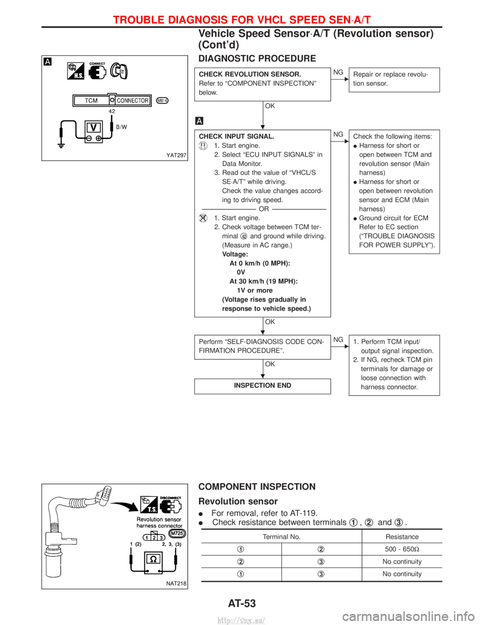
DIAGNOSTIC PROCEDURE
CHECK REVOLUTION SENSOR.
Refer to ªCOMPONENT INSPECTIONº
below.
OK
ENGRepair or replace revolu-
tion sensor.
CHECK INPUT SIGNAL.
1. Start engine.
2. Select ªECU INPUT SIGNALSº in Data Monitor.
3. Read out the value of ªVHCL/S SE×A/Tº while driving.
Check the value changes accord-
ing to driving speed.
---------------------------------------------------------------------------------------------------------------------- -OR -----------------------------------------------------------------------------------------------------------------------
1. Start engine.
2. Check voltage between TCM ter- minal q
42and ground while driving.
(Measure in AC range.)
Voltage: At 0 km/h (0 MPH):0V
At 30 km/h (19 MPH): 1V or more
(Voltage rises gradually in
response to vehicle speed.)
OK
ENG Check the following items:
IHarness for short or
open between TCM and
revolution sensor (Main
harness)
I Harness for short or
open between revolution
sensor and ECM (Main
harness)
I Ground circuit for ECM
Refer to EC section
(ªTROUBLE DIAGNOSIS
FOR POWER SUPPLYº).
Perform ªSELF-DIAGNOSIS CODE CON-
FIRMATION PROCEDUREº.
OK
ENG
1. Perform TCM input/
output signal inspection.
2. If NG, recheck TCM pin terminals for damage or
loose connection with
harness connector.
INSPECTION END
COMPONENT INSPECTION
Revolution sensor
I For removal, refer to AT-119.
I Check resistance between terminals q
1,q2and q3.
Terminal No.
Resistance
q
1q2500 - 650W
q
2q3No continuity
q
1q3No continuity
YAT297
NAT218
H
H
H
TROUBLE DIAGNOSIS FOR VHCL SPEED SEN ×A/T
Vehicle Speed Sensor×A/T (Revolution sensor)
(Cont'd)
AT-53
http://vnx.su/
Page 876 of 1833
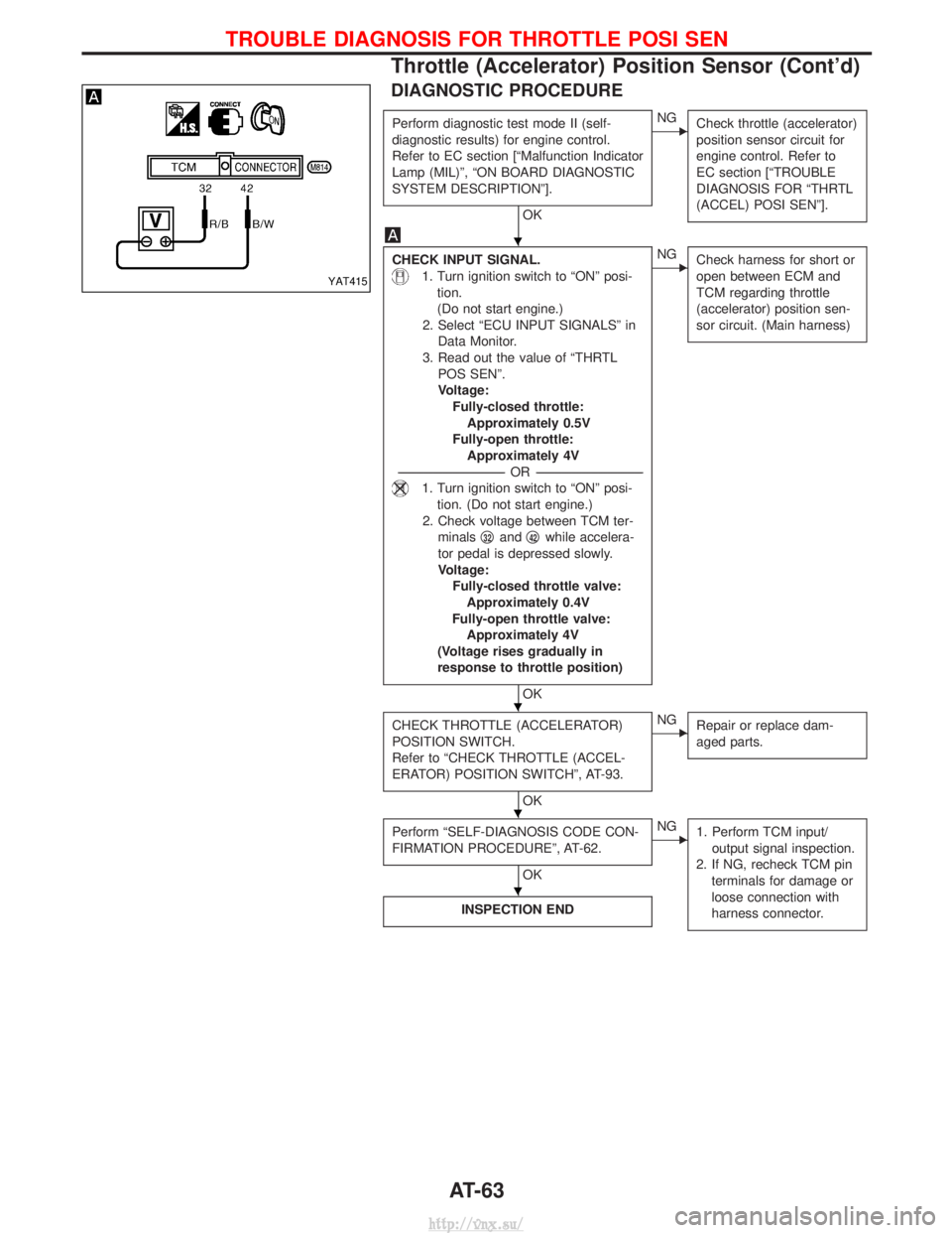
DIAGNOSTIC PROCEDURE
Perform diagnostic test mode II (self-
diagnostic results) for engine control.
Refer to EC section [ªMalfunction Indicator
Lamp (MIL)º, ªON BOARD DIAGNOSTIC
SYSTEM DESCRIPTIONº].
OK
ENGCheck throttle (accelerator)
position sensor circuit for
engine control. Refer to
EC section [ªTROUBLE
DIAGNOSIS FOR ªTHRTL
(ACCEL) POSI SENº].
CHECK INPUT SIGNAL.
1. Turn ignition switch to ªONº posi-
tion.
(Do not start engine.)
2. Select ªECU INPUT SIGNALSº in Data Monitor.
3. Read out the value of ªTHRTL POS SENº.
Voltage:Fully-closed throttle:Approximately 0.5V
Fully-open throttle: Approximately 4V
---------------------------------------------------------------------------------------------------------------------- -OR -----------------------------------------------------------------------------------------------------------------------
1. Turn ignition switch to ªONº posi-
tion. (Do not start engine.)
2. Check voltage between TCM ter- minals q
32andq42while accelera-
tor pedal is depressed slowly.
Voltage: Fully-closed throttle valve:Approximately 0.4V
Fully-open throttle valve: Approximately 4V
(Voltage rises gradually in
response to throttle position)
OK
ENG Check harness for short or
open between ECM and
TCM regarding throttle
(accelerator) position sen-
sor circuit. (Main harness)
CHECK THROTTLE (ACCELERATOR)
POSITION SWITCH.
Refer to ªCHECK THROTTLE (ACCEL-
ERATOR) POSITION SWITCHº, AT-93.
OK
ENGRepair or replace dam-
aged parts.
Perform ªSELF-DIAGNOSIS CODE CON-
FIRMATION PROCEDUREº, AT-62.
OK
ENG1. Perform TCM input/
output signal inspection.
2. If NG, recheck TCM pin terminals for damage or
loose connection with
harness connector.
INSPECTION END
YAT415
H
H
H
H
TROUBLE DIAGNOSIS FOR THROTTLE POSI SEN
Throttle (Accelerator) Position Sensor (Cont'd)
AT-63
http://vnx.su/