2004 NISSAN TERRANO Clutch pump fluid
[x] Cancel search: Clutch pump fluidPage 815 of 1833
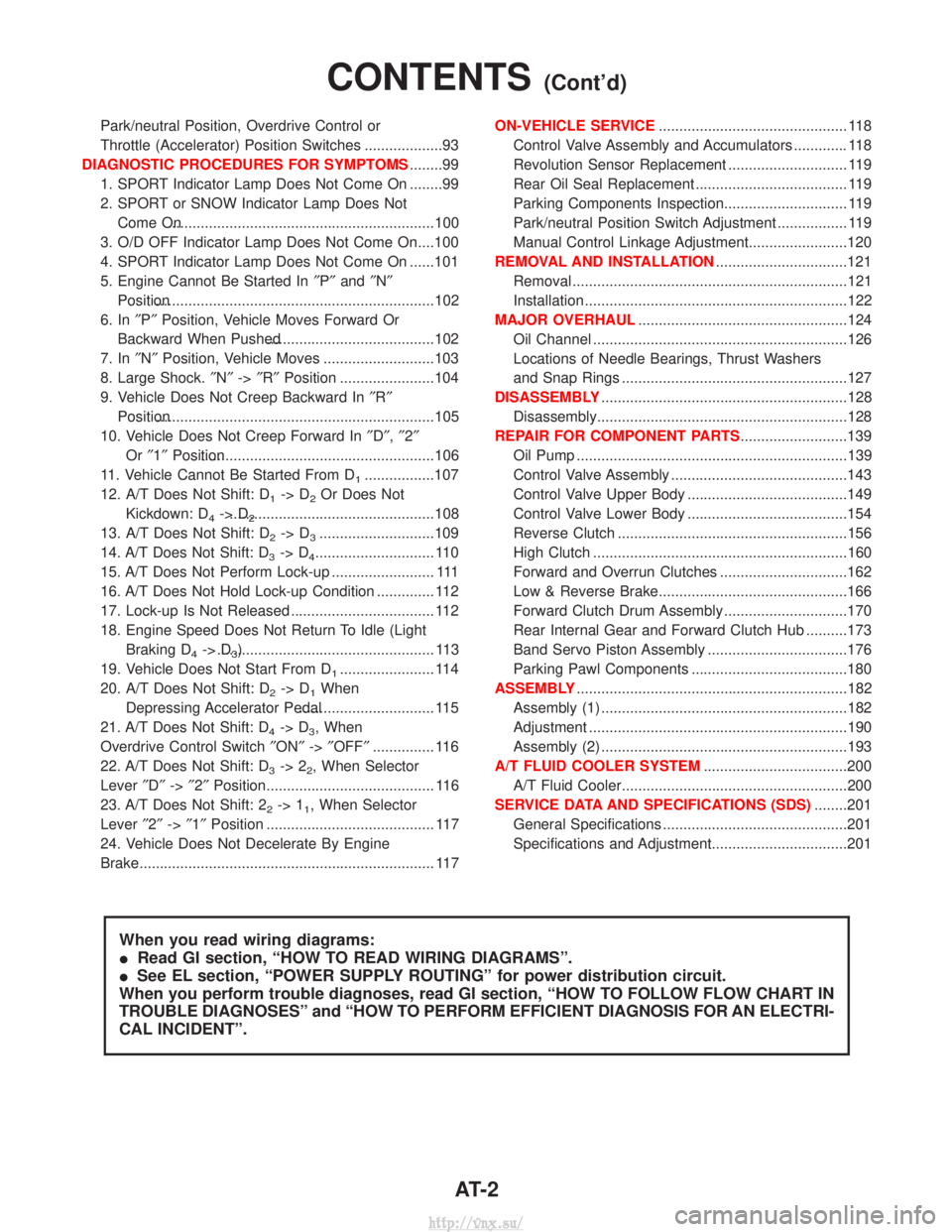
Park/neutral Position, Overdrive Control or
Throttle (Accelerator) Position Switches ...................93
DIAGNOSTIC PROCEDURES FOR SYMPTOMS ........99
1. SPORT Indicator Lamp Does Not Come On ........99
2. SPORT or SNOW Indicator Lamp Does Not Come On.................................................................100
3. O/D OFF Indicator Lamp Does Not Come On....100
4. SPORT Indicator Lamp Does Not Come On ......101
5. Engine Cannot Be Started In ²P² and ²N²
Position....................................................................102
6. In ²P² Position, Vehicle Moves Forward Or
Backward When Pushed.........................................102
7. In ²N² Position, Vehicle Moves ...........................103
8. Large Shock. ²N² ->²R² Position .......................104
9. Vehicle Does Not Creep Backward In ²R²
Position....................................................................105
10. Vehicle Does Not Creep Forward In ²D² ,²2²
Or ²1² Position.........................................................106
11. Vehicle Cannot Be Started From D
1.................107
12. A/T Does Not Shift: D
1-> D2Or Does Not
Kickdown: D
4-> D2..................................................108
13. A/T Does Not Shift: D
2-> D3............................109
14. A/T Does Not Shift: D
3-> D4............................. 110
15. A/T Does Not Perform Lock-up ......................... 111
16. A/T Does Not Hold Lock-up Condition .............. 112
17. Lock-up Is Not Released ................................... 112
18. Engine Speed Does Not Return To Idle (Light Braking D
4-> D3)..................................................... 113
19. Vehicle Does Not Start From D
1....................... 114
20. A/T Does Not Shift: D
2-> D1When
Depressing Accelerator Pedal................................. 115
21. A/T Does Not Shift: D
4-> D3, When
Overdrive Control Switch ²ON² ->²OFF² ............... 116
22. A/T Does Not Shift: D
3-> 22, When Selector
Lever ²D² ->²2² Position......................................... 116
23. A/T Does Not Shift: 2
2-> 11, When Selector
Lever ²2² ->²1² Position ......................................... 117
24. Vehicle Does Not Decelerate By Engine
Brake........................................................................\
117 ON-VEHICLE SERVICE
.............................................. 118
Control Valve Assembly and Accumulators ............. 118
Revolution Sensor Replacement ............................. 119
Rear Oil Seal Replacement ..................................... 119
Parking Components Inspection.............................. 119
Park/neutral Position Switch Adjustment ................. 119
Manual Control Linkage Adjustment........................120
REMOVAL AND INSTALLATION ................................121
Removal ...................................................................121
Installation ................................................................122
MAJOR OVERHAUL ...................................................124
Oil Channel ..............................................................126
Locations of Needle Bearings, Thrust Washers
and Snap Rings .......................................................127
DISASSEMBLY ............................................................128
Disassembly.............................................................128
REPAIR FOR COMPONENT PARTS ..........................139
Oil Pump ..................................................................139
Control Valve Assembly ...........................................143
Control Valve Upper Body .......................................149
Control Valve Lower Body .......................................154
Reverse Clutch ........................................................156
High Clutch ..............................................................160
Forward and Overrun Clutches ...............................162
Low & Reverse Brake..............................................166
Forward Clutch Drum Assembly ..............................170
Rear Internal Gear and Forward Clutch Hub ..........173
Band Servo Piston Assembly ..................................176
Parking Pawl Components ......................................180
ASSEMBLY ..................................................................182
Assembly (1) ............................................................182
Adjustment ...............................................................190
Assembly (2) ............................................................193
A/T FLUID COOLER SYSTEM ...................................200
A/T Fluid Cooler.......................................................200
SERVICE DATA AND SPECIFICATIONS (SDS) ........201
General Specifications .............................................201
Specifications and Adjustment.................................201
When you read wiring diagrams:
I Read GI section, ªHOW TO READ WIRING DIAGRAMSº.
I See EL section, ªPOWER SUPPLY ROUTINGº for power distribution circuit.
When you perform trouble diagnoses, read GI section, ªHOW TO FOLLOW FLOW CHART IN
TROUBLE DIAGNOSESº and ªHOW TO PERFORM EFFICIENT DIAGNOSIS FOR AN ELECTRI-
CAL INCIDENTº.
CONTENTS(Cont'd)
AT- 2
http://vnx.su/
Page 844 of 1833
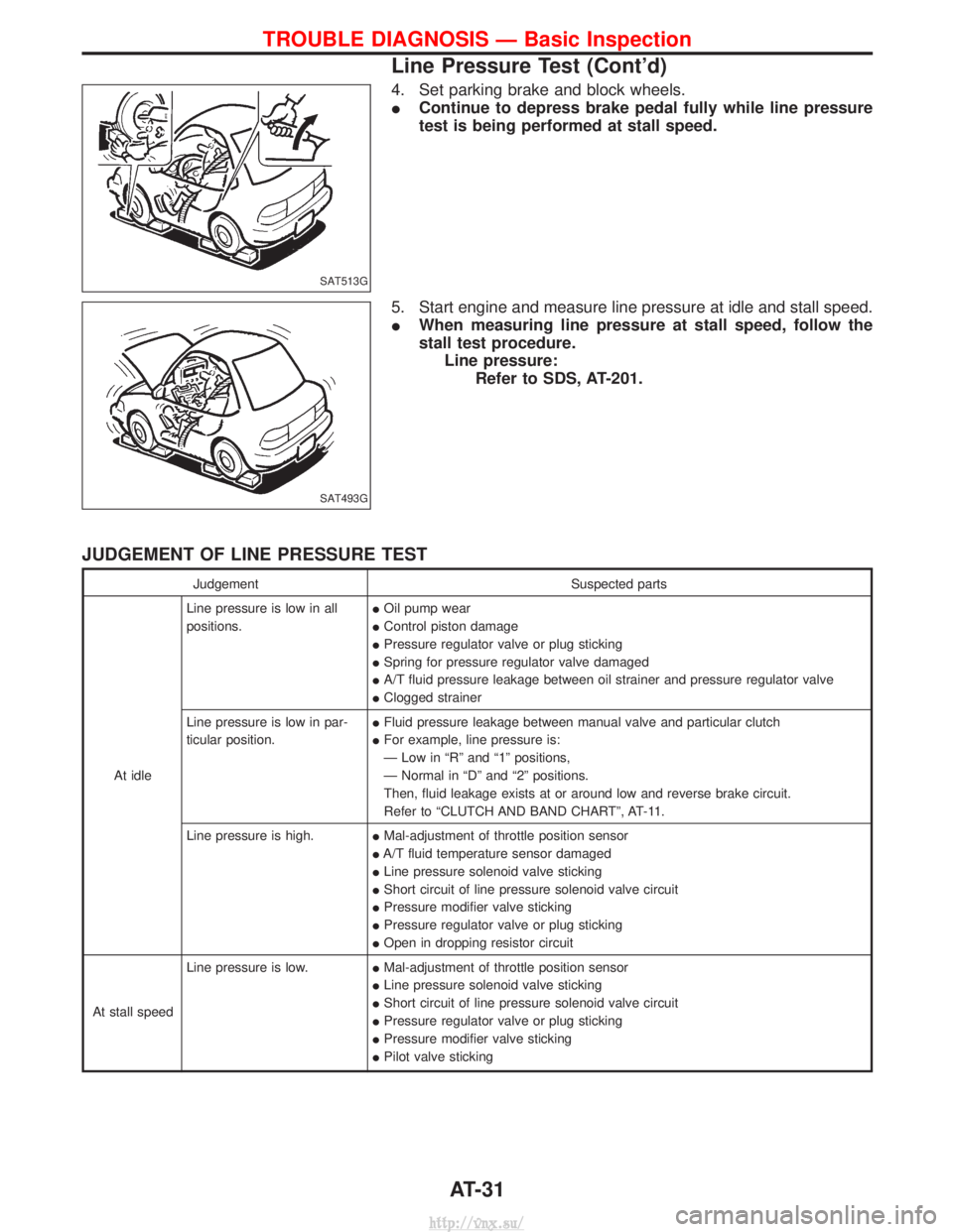
4. Set parking brake and block wheels.
IContinue to depress brake pedal fully while line pressure
test is being performed at stall speed.
5. Start engine and measure line pressure at idle and stall speed.
I When measuring line pressure at stall speed, follow the
stall test procedure.
Line pressure: Refer to SDS, AT-201.
JUDGEMENT OF LINE PRESSURE TEST
Judgement Suspected parts
At idle Line pressure is low in all
positions.
I
Oil pump wear
I Control piston damage
I Pressure regulator valve or plug sticking
I Spring for pressure regulator valve damaged
I A/T fluid pressure leakage between oil strainer and pressure regulator valve
I Clogged strainer
Line pressure is low in par-
ticular position. I
Fluid pressure leakage between manual valve and particular clutch
I For example, line pressure is:
Ð Low in ªRº and ª1º positions,
Ð Normal in ªDº and ª2º positions.
Then, fluid leakage exists at or around low and reverse brake circuit.
Refer to ªCLUTCH AND BAND CHARTº, AT-11.
Line pressure is high. IMal-adjustment of throttle position sensor
I A/T fluid temperature sensor damaged
I Line pressure solenoid valve sticking
I Short circuit of line pressure solenoid valve circuit
I Pressure modifier valve sticking
I Pressure regulator valve or plug sticking
I Open in dropping resistor circuit
At stall speed Line pressure is low.
IMal-adjustment of throttle position sensor
I Line pressure solenoid valve sticking
I Short circuit of line pressure solenoid valve circuit
I Pressure regulator valve or plug sticking
I Pressure modifier valve sticking
I Pilot valve sticking
SAT513G
SAT493G
TROUBLE DIAGNOSIS Ð Basic Inspection
Line Pressure Test (Cont'd)
AT-31
http://vnx.su/
Page 856 of 1833
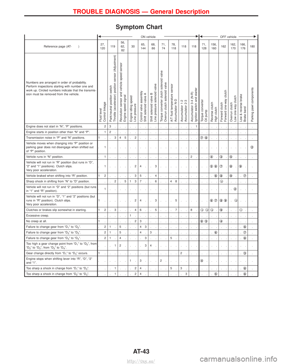
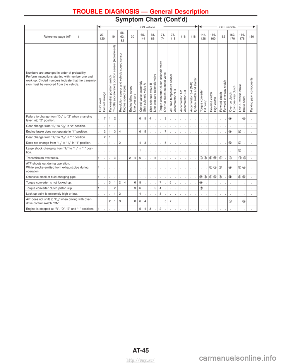
Symptom Chart
FON vehicleEFOFF vehicleE
Reference page (AT- )27,
120 11 9 56,
62,
82 30
65,
144 68,
86 71,
74 78,
11 8 11 8 11 8 71,
128 156,
160 162162,
170 166,
176 180
Numbers are arranged in order of probability.
Perform inspections starting with number one and
work up. Circled numbers indicate that the transmis-
sion must be removed from the vehicle.
Fluid level
Control linkage
Park/neutral position switch
Throttle (accelerator) position sensor (Adjustment)
Revolution sensor and vehicle speed sensor
Engine speed signal
Engine idling speed
Line pressure
Control valve assembly
Shift solenoid valve A
Shift solenoid valve B
Line pressure solenoid valve
Torque converter clutch solenoid valve
Overrun clutch solenoid valve
A/T fluid temperature sensor
Accumulator N-D
Accumulator 1-2
Accumulator 2-3
Accumulator 3-4 (N-R)
Ignition switch and starter
Torque converter
Oil pump
Reverse clutch
High clutch
Forward clutch
Forward one-way clutch
Overrun clutch
Low one-way clutch
Low & reverse brake
Brake band
Parking pawl components
Engine does not start in ªNº, ªPº positions. . 2 3................1. ......... .
Engine starts in position other than ªNº and ªPº. . 1 2 ................. . ......... .
Transmission noise in ªPº and ªNº positions. 1 . . 3 4 5 . 2 ............q
7q6........ .
Vehicle moves when changing into ªPº position or
parking gear does not disengage when shifted out
of ªPº position. . 1.................. .
.........q
2
Vehicle runs in ªNº position.
. 1................2. .. q4.q3.q5... .
Vehicle will not run in ªRº position (but runs in ªDº,
ª2º and ª1º positions). Clutch slips.
Very poor acceleration. . 1.....24..3........ ..
q
5q6q7.q8.q9..
Vehicle braked when shifting into ªRº position. 1 2 .....35..4........ ... q
6q8.q9.. q7.
Sharp shock in shifting from ªNº to ªDº position. . . . 2 . 5137 . . 6 . . 48.... ....q
10..... .
Vehicle will not run in ªDº and ª2º positions (but runs
in ª1º and ªRº position). . 1.................. .
......q
2.. .
Vehicle will not run in ªDº, ª1º and ª2º positions (but
runs in ªRº position). Clutch slips.
Very poor acceleration. 1 ......24..3...5.... ..
q
6q7q8q9.q10.. .
Clutches or brakes slip somewhat in starting. 1 2 . 3 . . . 4 6 . . 5 . . . 7 . . 8 . q
13q12q10.q9... q11..
Excessive creep. . .....1............. . ......... .
No creep at all. 1 ......23........... q
6q5..q4..... .
Failure to change gear from ªD
1ºtoªD2º. . 21.5...43.......... . ........q6.
Failure to change gear from ªD
2ºtoªD3º. . 21.5...4.3......... ... q6.....q7.
Failure to change gear from ªD
3ºtoªD4º. . 21.4....3....5..... . ........q6.
Too high a gear change point from ªD
1ºtoªD2º, from
ªD2ºtoªD3º, from ªD3ºtoªD4º. . ..12....34......... .
......... .
Gear change directly from ªD
1ºtoªD3º occurs. 1 ...............2... . ........q3.
Engine stops when shifting lever into ªRº, ªDº, ª2º
and ª1º. . .....1.3...2.......
q
4......... .
Too sharp a shock in change from ªD
1ºtoªD2º. . ..1...24.....5.3... . ........q6.
Too sharp a shock in change from ªD
2ºtoªD3º. . ..1...24........3.. ... q5.....q6.
TROUBLE DIAGNOSIS Ð General Description
AT-43
http://vnx.su/
Page 857 of 1833
FON vehicleEFOFF vehicleE
Reference page (AT- )27,
120 11 9 56,
62,
82 30
65,
144 68,
86 71,
74 78,
11 8 11 8 11 8 71,
128 156,
160 162162,
170 166,
176 180
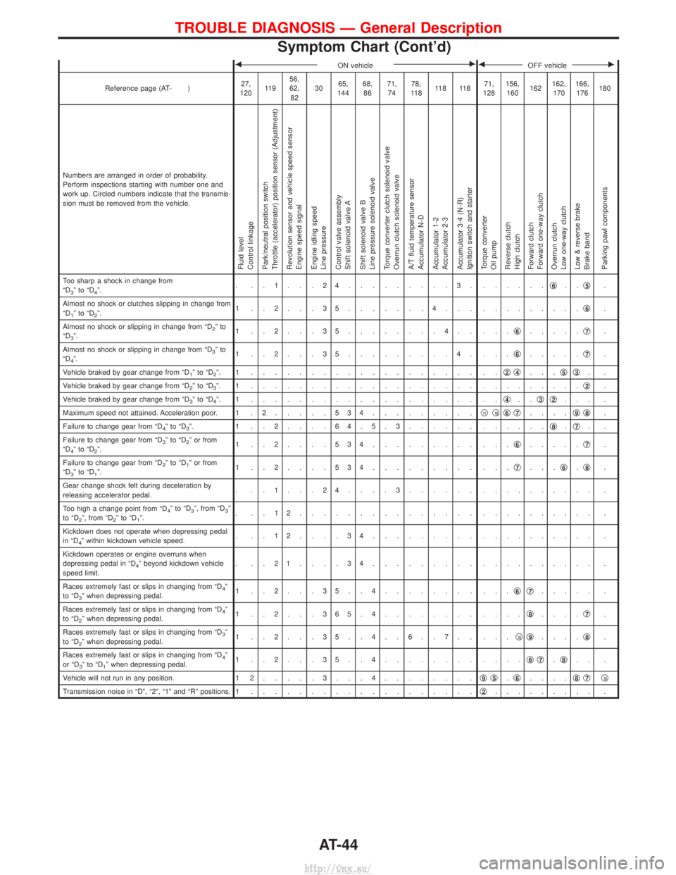
Numbers are arranged in order of probability.
Perform inspections starting with number one and
work up. Circled numbers indicate that the transmis-
sion must be removed from the vehicle.
Fluid level
Control linkage
Park/neutral position switch
Throttle (accelerator) position sensor (Adjustment)
Revolution sensor and vehicle speed sensor
Engine speed signal
Engine idling speed
Line pressure
Control valve assembly
Shift solenoid valve A
Shift solenoid valve B
Line pressure solenoid valve
Torque converter clutch solenoid valve
Overrun clutch solenoid valve
A/T fluid temperature sensor
Accumulator N-D
Accumulator 1-2
Accumulator 2-3
Accumulator 3-4 (N-R)
Ignition switch and starter
Torque converter
Oil pump
Reverse clutch
High clutch
Forward clutch
Forward one-way clutch
Overrun clutch
Low one-way clutch
Low & reverse brake
Brake band
Parking pawl components
Too sharp a shock in change from
ªD3ºtoªD4º. . ..1...24.........3. .
.....q6..q5.
Almost no shock or clutches slipping in change from
ªD
1ºtoªD2º. 1 ..2...35.......4... .
........q6.
Almost no shock or slipping in change from ªD
2ºto
ªD3º. 1 ..2...35........4.. ...
q6.....q7.
Almost no shock or slipping in change from ªD
3ºto
ªD4º. 1 ..2...35.........4. ...
q6.....q7.
Vehicle braked by gear change from ªD
1ºtoªD2º. 1 ................... .. q2q4...q5q3..
Vehicle braked by gear change from ªD
2ºtoªD3º. 1 ................... . ........q2.
Vehicle braked by gear change from ªD
3ºtoªD4º. 1 ................... .. q4..q3q2... .
Maximum speed not attained. Acceleration poor. 1 . 2 .....534.........q
11q10q6q7....q9q8.
Failure to change gear from ªD
4ºtoªD3º. 1 ..2....64.5.3...... . .....q8.q7..
Failure to change gear from ªD
3ºtoªD2º or from
ªD4ºtoªD2º. 1 ..2....534......... ...
q6.....q7.
Failure to change gear from ªD
2ºtoªD1º or from
ªD3ºtoªD1º. 1 ..2....534......... ...
q7...q6.q8.
Gear change shock felt during deceleration by
releasing accelerator pedal. . ..1...24....3...... .
......... .
Too high a change point from ªD
4ºtoªD3º, from ªD3º
to ªD2º, from ªD2ºtoªD1º. . ..12............... .
......... .
Kickdown does not operate when depressing pedal
in ªD
4º within kickdown vehicle speed. . ..12....34......... .
......... .
Kickdown operates or engine overruns when
depressing pedal in ªD
4º beyond kickdown vehicle
speed limit. . ..21....34......... .
......... .
Races extremely fast or slips in changing from ªD
4º
to ªD3º when depressing pedal. 1 ..2...35..4........ ...
q6q7..... .
Races extremely fast or slips in changing from ªD
4º
to ªD2º when depressing pedal. 1 ..2...365.4........ ....
q8....q7.
Races extremely fast or slips in changing from ªD
3º
to ªD2º when depressing pedal. 1 ..2...35..4..6..7.. ...
q10q9....q8.
Races extremely fast or slips in changing from ªD
4º
or ªD3ºtoªD1º when depressing pedal. 1 ..2...35..4........ ....
q6q7.q8.. .
Vehicle will not run in any position. 1 2 .....3...4........ q
9q5.q6.... q8q7q10
Transmission noise in ªDº, ª2º, ª1º and ªRº positions. 1
................... q2......... .
TROUBLE DIAGNOSIS Ð General Description
Symptom Chart (Cont'd)
AT-44
http://vnx.su/
Page 858 of 1833
FON vehicleEFOFF vehicleE
Reference page (AT- )27,
120 11 9 56,
62,
82 30
65,
144 68,
86 71,
74 78,
11 8 11 8 11 8 144,
128 156,
160 162162,
170 166,
176 180
Numbers are arranged in order of probability.
Perform inspections starting with number one and
work up. Circled numbers indicate that the transmis-
sion must be removed from the vehicle.
Fluid level
Control linkage
Park/neutral position switch
Throttle (accelerator) position sensor (Adjustment)
Revolution sensor and vehicle speed sensor
Engine speed signal
Engine idling speed
Line pressure
Control valve assembly
Shift solenoid valve A
Shift solenoid valve B
Line pressure solenoid valve
Torque converter clutch solenoid valve
Overrun clutch solenoid valve
A/T fluid temperature sensor
Accumulator N-D
Accumulator 1-2
Accumulator 2-3
Accumulator 3-4 (N-R)
Ignition switch and starter
Torque converter
Oil pump
Reverse clutch
High clutch
Forward clutch
Forward one-way clutch
Overrun clutch
Low one-way clutch
Low & reverse brake
Brake band
Parking pawl components
Failure to change from ªD3º to ª2º when changing
lever into ª2º position. . 712....654..3...... .
.....q9..q8.
Gear change from ª2
1ºtoª22º in ª2º position. . . 1 ................. . ......... .
Engine brake does not operate in ª1º position. . 2134 . . . 65 . . . 7...... ......q
8.q9..
Gear change from ª1
1ºtoª12º in ª1º position. . 2 1 ................. . ......... .
Does not change from ª1
2ºtoª11º in ª1º position. . . 1 . 2 . . . 4 3 . . . 5 ...... ......q6.q7..
Large shock changing from ª1
2ºtoª11º in ª1º posi-
tion. . .......1........... .
.......q2..
Transmission overheats. 1 . . 3 . . 2 4 6 . . 5 ........q
14q7q8q9q11.q12.q13q10.
ATF shoots out during operation.
White smoke emitted from exhaust pipe during
operation. 1 ................... ..
q
2q3q5.q6.q7q4.
Offensive smell at fluid charging pipe. 1 ................... q
2q3q4q5q7.q8.q9q6.
Torque converter is not locked up. . . 3124 . 68 . . . 7 . 5.....q
9......... .
Torque converter clutch piston slip 1 . . 2 . . . 3 6 . . 5 4 .......q
7......... .
Lock-up point is extremely high or low. . . . 1 2 . . . 4 . . . 3 ....... .......... .
A/T does not shift to ªD
4º when driving with over-
drive control switch ªONº. . .213..864...57..... .
.....q10..q9.
Engine is stopped at ªRº, ªDº, ª2º and ª1º positions. 1 .......543.2....... . ......... .
TROUBLE DIAGNOSIS Ð General Description
Symptom Chart (Cont'd)
AT-45
http://vnx.su/
Page 918 of 1833
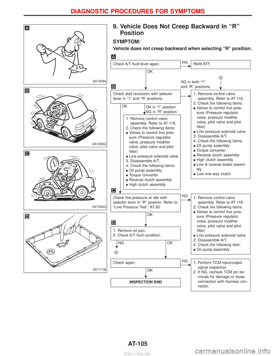
9. Vehicle Does Not Creep Backward In ªRºPosition
SYMPTOM:
Vehicle does not creep backward when selecting ªRº position.
Check A/T fluid level again.
OK
ENG Refill ATF.
qA
NG in both ª1º
and ªRº positions
Check stall revolution with selector
lever in ª1º and ªRº positions.
OK OK in ª1º position
NG in ªRº position
E1. Remove control valve
assembly. Refer to AT-118.
2. Check the following items:
I Valves to control line pres-
sure (Pressure regulator
valve, pressure modifier
valve, pilot valve and pilot
filter)
I Line pressure solenoid valve
3. Disassemble A/T.
4. Check the following items:
I Oil pump assembly
I Torque converter
I Reverse clutch assembly
I High clutch assembly
I Low & reverse brake assem-
bly
I Low one-way clutch
1. Remove control valve
assembly. Refer to AT-118.
2. Check the following items:
I Valves to control line pres-
sure (Pressure regulator
valve, pressure modifier
valve, pilot valve and pilot
filter)
I Line pressure solenoid valve
3. Disassemble A/T.
4. Check the following items:
I Oil pump assembly
I Torque converter
I Reverse clutch assembly
I High clutch assembly
Check line pressure at idle with
selector lever in ªRº position. Refer to
ªLine Pressure Testº, AT-30.
OK
ENG
1. Remove control valve
assembly. Refer to AT-118.
2. Check the following items:
I Valves to control line pres-
sure (Pressure regulator
valve, pressure modifier
valve, pilot valve and pilot
filter)
I Line pressure solenoid valve
3. Disassemble A/T.
4. Check the following item:
I Oil pump assembly
1. Remove oil pan.
2. Check A/T fluid condition.
NG OK
q
A
Check again.
OK
ENG 1. Perform TCM input/output
signal inspection.
2. If NG, recheck TCM pin ter- minals for damage or loose
connection with harness con-
nector.
INSPECTION END
SAT638A
SAT493G
SAT494G
SAT171B
HH
H
H
H
H
H
H
DIAGNOSTIC PROCEDURES FOR SYMPTOMS
AT-105
http://vnx.su/
Page 919 of 1833
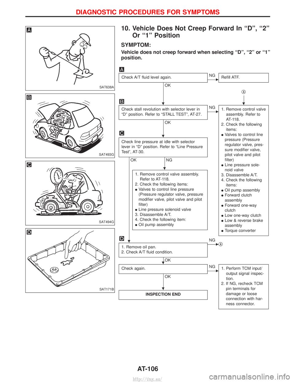
10. Vehicle Does Not Creep Forward In ªDº, ª2ºOr ª1º Position
SYMPTOM:
Vehicle does not creep forward when selecting ªDº, ª2º or ª1º
position.
Check A/T fluid level again.
OK
ENG Refill ATF.
qA
Check stall revolution with selector lever in
ªDº position. Refer to ªSTALL TESTº, AT-27.
OK
ENG1. Remove control valve
assembly. Refer to
AT-118.
2. Check the following items:
I Valves to control line
pressure (Pressure
regulator valve, pres-
sure modifier valve,
pilot valve and pilot
filter)
I Line pressure sole-
noid valve
3. Disassemble A/T.
4. Check the following items:
I Oil pump assembly
I Forward clutch
assembly
I Forward one-way
clutch
I Low one-way clutch
I Low & reverse brake
assembly
I Torque converter
Check line pressure at idle with selector
lever in ªDº position. Refer to ªLine Pressure
Testº, AT-30.
OK NG
1. Remove control valve assembly. Refer to AT-118.
2. Check the following items:
I Valves to control line pressure
(Pressure regulator valve, pressure
modifier valve, pilot valve and pilot
filter)
I Line pressure solenoid valve
3. Disassemble A/T.
4. Check the following item:
I Oil pump assembly
1. Remove oil pan.
2. Check A/T fluid condition.
OK
ENG qA
Check again.
OK
ENG 1. Perform TCM input/
output signal inspec-
tion.
2. If NG, recheck TCM pin terminals for
damage or loose
connection with har-
ness connector.
INSPECTION END
SAT638A
SAT493G
SAT494G
SAT171B
HH
H
H
H
HH
H
DIAGNOSTIC PROCEDURES FOR SYMPTOMS
AT-106
http://vnx.su/
Page 920 of 1833
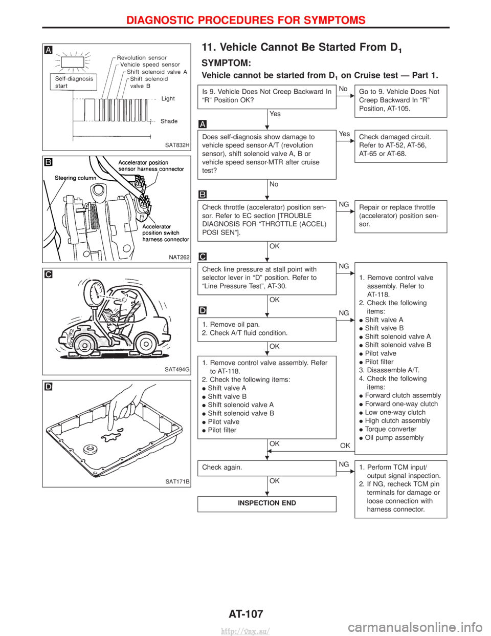
11. Vehicle Cannot Be Started From D1
SYMPTOM:
Vehicle cannot be started from D1on Cruise test Ð Part 1.
Is 9. Vehicle Does Not Creep Backward In
ªRº Position OK?
Ye s
ENoGo to 9. Vehicle Does Not
Creep Backward In ªRº
Position, AT-105.
Does self-diagnosis show damage to
vehicle speed sensor×A/T (revolution
sensor), shift solenoid valve A, B or
vehicle speed sensor×MTR after cruise
test?
No
EYe sCheck damaged circuit.
Refer to AT-52, AT-56,
AT-65 or AT-68.
Check throttle (accelerator) position sen-
sor. Refer to EC section [TROUBLE
DIAGNOSIS FOR ªTHROTTLE (ACCEL)
POSI SENº].
OK
ENGRepair or replace throttle
(accelerator) position sen-
sor.
Check line pressure at stall point with
selector lever in ªDº position. Refer to
ªLine Pressure Testº, AT-30.
OK
ENG
1. Remove control valveassembly. Refer to
AT-118.
2. Check the following items:
I Shift valve A
I Shift valve B
I Shift solenoid valve A
I Shift solenoid valve B
I Pilot valve
I Pilot filter
3. Disassemble A/T.
4. Check the following items:
I Forward clutch assembly
I Forward one-way clutch
I Low one-way clutch
I High clutch assembly
I Torque converter
I Oil pump assembly
1. Remove oil pan.
2. Check A/T fluid condition.
OK
ENG
1. Remove control valve assembly. Refer to AT-118.
2. Check the following items:
I Shift valve A
I Shift valve B
I Shift solenoid valve A
I Shift solenoid valve B
I Pilot valve
I Pilot filter
OKFOK
Check again.
OK
ENG 1. Perform TCM input/
output signal inspection.
2. If NG, recheck TCM pin terminals for damage or
loose connection with
harness connector.
INSPECTION END
SAT832H
NAT262
SAT494G
SAT171B
H
H
H
H
H
HH
H
DIAGNOSTIC PROCEDURES FOR SYMPTOMS
AT-107
http://vnx.su/