2004 NISSAN TERRANO torque
[x] Cancel search: torquePage 4 of 1833

GENERAL INFORMATIONSECTION
GI
CONTENTS
PRECAUTIONS ...............................................................2
Supplemental Restraint System (SRS) ²AIR
BAG² and²SEAT BELT PRE-TENSIONER²
(Dual Air Bag System) .................................................3
Precautions for NATS ..................................................4
Precautions for Multiport Fuel Injection System
or Engine Control System ...........................................5
Precautions for Catalyst ..............................................5
Precautions for Turbocharger ......................................5
Precautions for Fuel ....................................................6
Precautions for Engine Oils .........................................6
HOW TO USE THIS MANUAL ........................................8
HOW TO READ WIRING DIAGRAMS ..........................10
Sample/Wiring Diagram - EXAMPL - ........................10
Description .................................................................12
HOW TO CHECK TERMINAL .......................................19
How to Probe Connectors .........................................19
How to Check Enlarged Contact Spring of
Terminal .....................................................................20
Waterproof Connector Inspection ..............................21
Terminal Lock Inspection ...........................................21
HOW TO PERFORM EFFICIENT DIAGNOSIS FOR
AN ELECTRICAL INCIDENT ........................................22 Work Flow ..................................................................22
Incident Simulation Tests ...........................................23
HOW TO FOLLOW FLOW CHART IN TROUBLE
DIAGNOSES ..................................................................25
CONSULT-II CHECKING SYSTEM ...............................26
Function and System Application ..............................26
Nickel Metal Hydride Battery Replacement...............26
Checking Equipment..................................................26
IDENTIFICATION INFORMATION .................................27
Model Variation ..........................................................27
Identification Number .................................................28
Dimensions ................................................................30
Wheels and Tires .......................................................30
LIFTING POINTS AND TOW TRUCK TOWING ...........31
Garage Jack and Safety Stand .................................31
Screw Jack ................................................................31
4-pole Lift ...................................................................32
Tow Truck Towing ......................................................32
ISO 15031-2 TERMINOLOGY LIST ..............................34
ISO 15031-2 Terminology List ...................................34
TIGHTENING TORQUE OF STANDARD BOLTS ........37
http://vnx.su/
Page 11 of 1833
1.A QUICK REFERENCE INDEX , a black tab (e.g.) is provided on the first page. You can quickly find
the first page of each section by mating it to the section's black tab.
2. THE CONTENTS are listed on the first page of each section.
3. THE TITLE is indicated on the upper portion of each page and shows the part or system.
4. THE PAGE NUMBER of each section consists of two letters which designate the particular section and a
number (e.g. ªBR-5º).
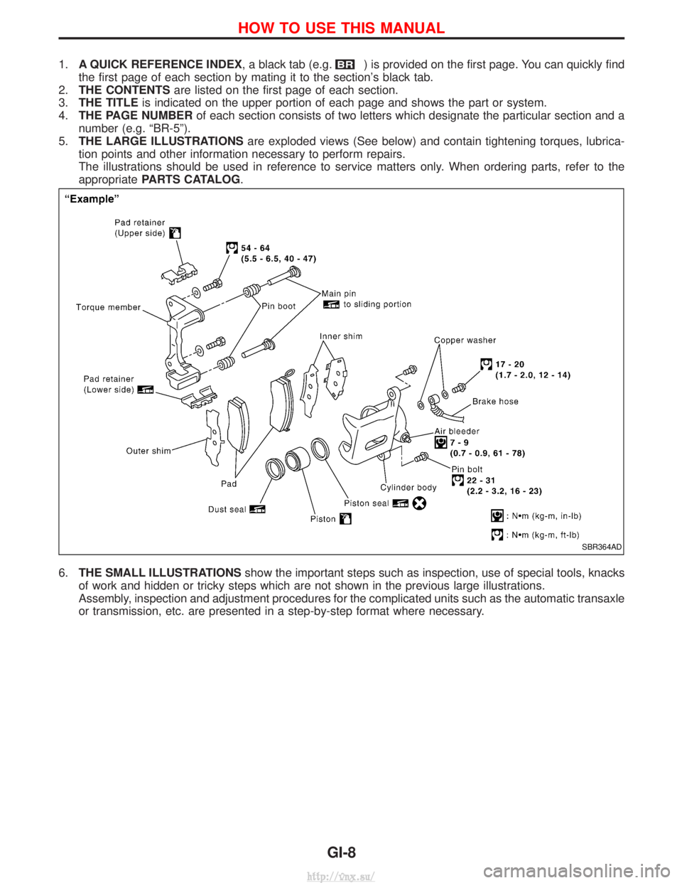
5. THE LARGE ILLUSTRATIONS are exploded views (See below) and contain tightening torques, lubrica-
tion points and other information necessary to perform repairs.
The illustrations should be used in reference to service matters only. When ordering parts, refer to the
appropriate PARTS CATALOG .
6. THE SMALL ILLUSTRATIONS show the important steps such as inspection, use of special tools, knacks
of work and hidden or tricky steps which are not shown in the previous large illustrations.
Assembly, inspection and adjustment procedures for the complicated units such as the automatic transaxle
or transmission, etc. are presented in a step-by-step format where necessary.
SBR364AD
HOW TO USE THIS MANUAL
GI-8
http://vnx.su/
Page 12 of 1833
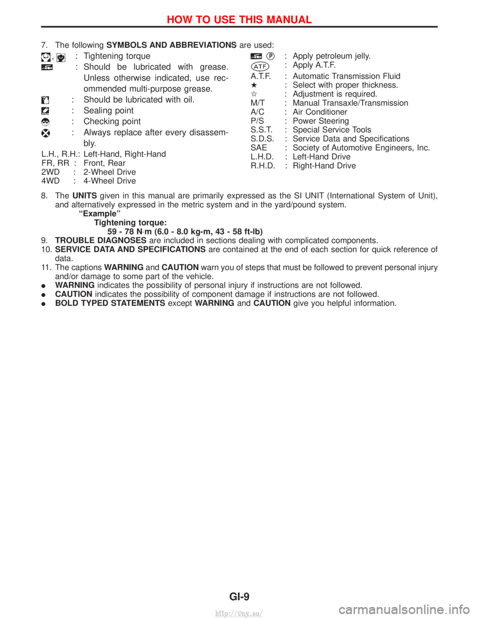
7. The followingSYMBOLS AND ABBREVIATIONS are used:
,: Tightening torque
: Should be lubricated with grease.
Unless otherwise indicated, use rec-
ommended multi-purpose grease.
: Should be lubricated with oil.
: Sealing point
: Checking point
: Always replace after every disassem- bly.
L.H., R.H.: Left-Hand, Right-Hand
FR, RR : Front, Rear
2WD : 2-Wheel Drive
4WD : 4-Wheel Drive
qP: Apply petroleum jelly.
: Apply A.T.F.
A.T.F. : Automatic Transmission Fluid
H : Select with proper thickness.
I : Adjustment is required.
M/T : Manual Transaxle/Transmission
A/C : Air Conditioner
P/S : Power Steering
S.S.T. : Special Service Tools
S.D.S. : Service Data and Specifications
SAE : Society of Automotive Engineers, Inc.
L.H.D. : Left-Hand Drive
R.H.D. : Right-Hand Drive
8. The UNITSgiven in this manual are primarily expressed as the SI UNIT (International System of Unit),
and alternatively expressed in the metric system and in the yard/pound system. ªExampleºTightening torque:59-78N ×m (6.0 - 8.0 kg-m, 43 - 58 ft-lb)
9. TROUBLE DIAGNOSES are included in sections dealing with complicated components.
10. SERVICE DATA AND SPECIFICATIONS are contained at the end of each section for quick reference of
data.
11. The captions WARNINGandCAUTION warn you of steps that must be followed to prevent personal injury
and/or damage to some part of the vehicle.
I WARNING indicates the possibility of personal injury if instructions are not followed.
I CAUTION indicates the possibility of component damage if instructions are not followed.
I BOLD TYPED STATEMENTS exceptWARNING andCAUTION give you helpful information.
HOW TO USE THIS MANUAL
GI-9
http://vnx.su/
Page 39 of 1833

***: Not applicable
NEW TERMNEW ACRONYM/
ABBREVIATION OLD TERM
Powertrain control module PCM ***
Programmable read only memory PROM ***
Pulsed secondary air injection control solenoid
valve PAIRC solenoid valve AIV control solenoid valve
Pulsed secondary air injection system PAIR system Air induction valve (AIV) control
Pulsed secondary air injection valve PAIR valve Air induction valve
Random access memory RAM ***
Read only memory ROM ***
Scan tool ST ***
Secondary air injection pump AIR pump ***
Secondary air injection system AIR system ***
Sequential multiport fuel injection system SFI system Sequential fuel injection
Service reminder indicator SRI ***
Simultaneous multiport fuel injection system *** Simultaneous fuel injection
Smoke puff limiter system SPL system ***
Supercharger SC ***
Supercharger bypass SCB ***
System readiness test SRT ***
Thermal vacuum valve TVV Thermal vacuum valve
Three way catalyst TWC Catalyst
Three way catalytic converter system TWC system ***
Three way + oxidation catalyst TWC + OC Catalyst
Three way + oxidation catalytic converter system TWC + OC system ***
Throttle body TB Throttle chamber
SPI body
Throttle body fuel injection system TBI system Fuel injection control
Throttle position TP Throttle position
Throttle position sensor TPS Throttle sensor
Throttle position switch TP switch Throttle switch
Torque converter clutch solenoid valve TCC solenoid valve Lock-up cancel solenoid
lock-up solenoid
Turbocharger TC Turbocharger
Vehicle speed sensor VSS Vehicle speed sensor
Volume air flow sensor VAFS Air flow meter
Warm up oxidation catalyst WU-OC Catalyst
Warm up oxidation catalytic converter system WU-OC system ***
Warm up three-way catalyst WU-TWC Catalyst
Warm up three-way catalytic converter system WU-TWC system ***
Wide open throttle position switch WOP switch Full switch
ISO 15031-2 TERMINOLOGY LIST
ISO 15031-2 Terminology List (Cont'd)
GI-36
http://vnx.su/
Page 40 of 1833
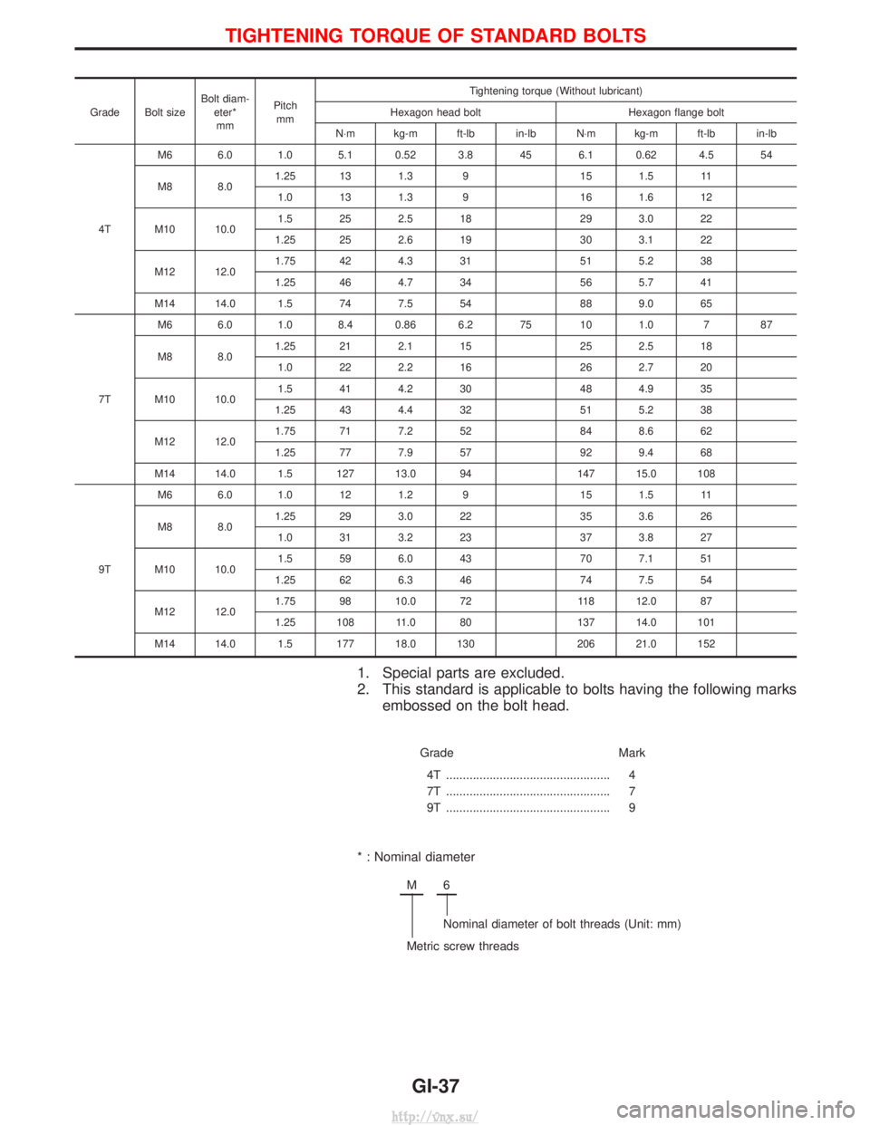
Grade Bolt sizeBolt diam-
eter*mm Pitch
mm Tightening torque (Without lubricant)
Hexagon head bolt Hexagon flange bolt
N×m kg-m ft-lb in-lb N ×m kg-m ft-lb in-lb
4T M6 6.0 1.0 5.1 0.52 3.8 45 6.1 0.62 4.5 54
M8 8.0
1.25 13 1.3 9 15 1.5 11
1.0 13 1.3 9 16 1.6 12
M10 10.0 1.5 25 2.5 18 29 3.0 22
1.25 25 2.6 19 30 3.1 22
M12 12.0 1.75 42 4.3 31 51 5.2 38
1.25 46 4.7 34 56 5.7 41
M14 14.0 1.5 74 7.5 54 88 9.0 65
7T M6 6.0 1.0 8.4 0.86 6.2 75 10 1.0 7 87
M8 8.0
1.25 21 2.1 15 25 2.5 18
1.0 22 2.2 16 26 2.7 20
M10 10.0 1.5 41 4.2 30 48 4.9 35
1.25 43 4.4 32 51 5.2 38
M12 12.0 1.75 71 7.2 52 84 8.6 62
1.25 77 7.9 57 92 9.4 68
M14 14.0 1.5 127 13.0 94 147 15.0 108
9T M6 6.0 1.0 12 1.2 9 15 1.5 11
M8 8.0
1.25 29 3.0 22 35 3.6 26
1.0 31 3.2 23 37 3.8 27
M10 10.0 1.5 59 6.0 43 70 7.1 51
1.25 62 6.3 46 74 7.5 54
M12 12.0 1.75 98 10.0 72 118 12.0 87
1.25 108 11.0 80 137 14.0 101
M14 14.0 1.5 177 18.0 130 206 21.0 152
1. Special parts are excluded.
2. This standard is applicable to bolts having the following marks embossed on the bolt head.
Grade Mark
4T .................................................
7T .................................................
9T ................................................. 4
7
9
* : Nominal diameter
M6
Nominal diameter of bolt threads (Unit: mm)
Metric screw threads
TIGHTENING TORQUE OF STANDARD BOLTS
GI-37
http://vnx.su/
Page 42 of 1833
MAINTENANCE
SECTION
MA
CONTENTS
PRE-DELIVERY INSPECTION ITEMS ............................3
GENERAL MAINTENANCE ............................................4
PERIODIC MAINTENANCE ............................................5
Maintenance Schedule for Diesel Engine Models
(annual mileage < 30,000 km/year) ............................5
Maintenance Schedule for Diesel Engine Models
(annual mileage > 30,000 km/year) ............................8
Maintenance Under Severe Driving Conditions
(annual mileage < 30,000 km/year) .......................... 11
Maintenance Under Severe Driving Conditions
(annual mileage > 30,000 km/year) ..........................14
RECOMMENDED FLUIDS AND LUBRICANTS ...........17
Fluids and Lubricants ................................................17
SAE Viscosity Number ..............................................18
Engine Coolant Mixture Ratio....................................19
TD
ENGINE MAINTENANCE ..............................................20
Retightening Manifold Bolts and Nuts .......................20
Adjusting Intake and Exhaust Valve Clearance ........20
Drive Belt Inspection..................................................20
Changing Engine Oil..................................................21
Changing Oil Filter .....................................................21
Changing Engine Coolant..........................................22
Checking Cooling System .........................................23
Checking and Replacing fuel filter and Draining
Water ........................................................................\
.23
Cleaning and Replacing Air Cleaner Filter (Dry
paper type).................................................................24
Checking Injection Nozzle .........................................25
Checking Idle Speed .................................................26
ZD
ENGINE MAINTENANCE ..............................................28
Checking Tightening Torque ......................................28
Adjusting Intake and Exhaust Valve Clearance ........28
Checking Drive Belt ...................................................28
Removal .....................................................................29 Installation ..................................................................29
Changing Engine Oil..................................................29
Changing Engine Oil Filter ........................................30
Changing Engine Coolant..........................................31
Checking Cooling System .........................................32
Checking and Replacing Fuel Filter and Draining
Water ........................................................................\
.33
Checking Fuel Lines ..................................................34
Cleaning and Replacing Air Cleaner Filter ................35
CHASSIS AND BODY MAINTENANCE .......................36
Checking Exhaust System.........................................36
Checking Clutch Operation........................................36
Checking Clutch Fluid Level and Leaks ....................36
Checking Clutch System ...........................................36
Checking M/T Oil .......................................................36
Changing M/T Oil.......................................................37
Checking Water Entry ................................................37
Checking Transfer Oil ................................................37
Changing Transfer Oil................................................38
Checking Propeller Shaft ...........................................38
Checking Differential Gear Oil ...................................38
Changing Differential Gear Oil ..................................39
Checking Front Wheel Bearing Grease ....................39
Repacking Front Wheel Bearing Grease ..................39
Checking Free-running Hub Grease .........................40
Checking Brake Fluid Level and Leaks.....................40
Checking Brake System ............................................40
Checking Brake Booster, Vacuum Hoses,
Connections and Check Valve ..................................40
Checking Disc Brake .................................................40
Checking Drum Brake ...............................................41
Checking Foot Brake Pedal Operation......................42
Checking Parking Brake ............................................42
Changing Brake Fluid ................................................43
Balancing Wheels ......................................................43
Tire Rotation ..............................................................43
Checking Steering Gear and Linkage .......................43
Checking Fluid Level and Leaks (Power steering) ...44
http://vnx.su/
Page 69 of 1833
Checking Tightening Torque
Checking should be performed while engine is cold.
MANIFOLD BOLTS AND NUTS
Intake and exhaust manifolds:Intake
:25-28N ×m (2.5 - 2.9 kg-m, 18 - 20 ft-lb)
Exhaust
:40-44N ×m (4.0 - 4.5 kg-m, 29 - 32 ft-lb)
Adjusting Intake and Exhaust Valve Clearance
Refer to EM section.
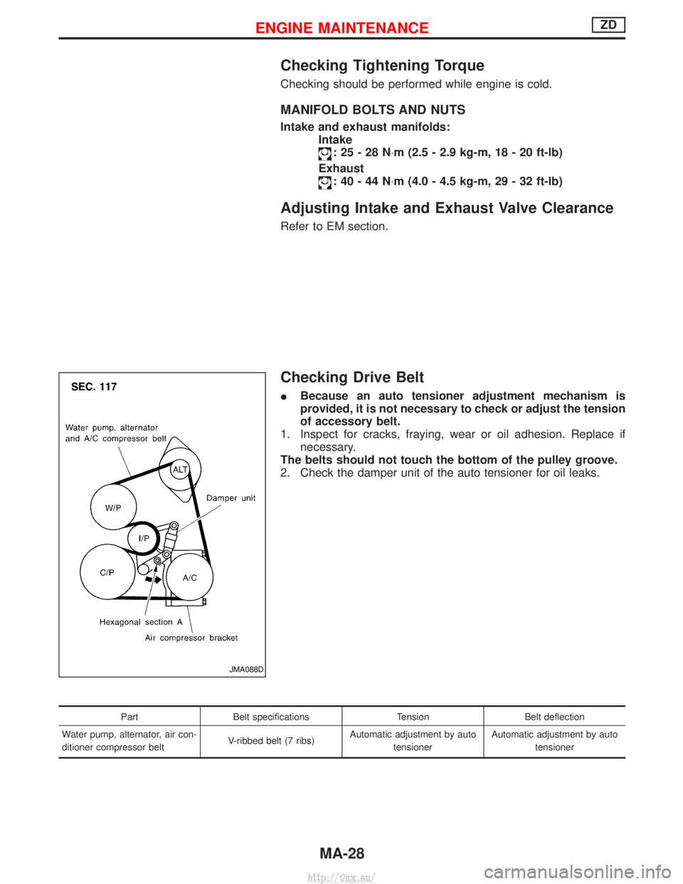
Checking Drive Belt
IBecause an auto tensioner adjustment mechanism is
provided, it is not necessary to check or adjust the tension
of accessory belt.
1. Inspect for cracks, fraying, wear or oil adhesion. Replace if necessary.
The belts should not touch the bottom of the pulley groove.
2. Check the damper unit of the auto tensioner for oil leaks.
Part Belt specifications TensionBelt deflection
Water pump, alternator, air con-
ditioner compressor belt V-ribbed belt (7 ribs)Automatic adjustment by auto
tensioner Automatic adjustment by auto
tensioner
JMA088D
ENGINE MAINTENANCEZD
MA-28
http://vnx.su/
Page 91 of 1833
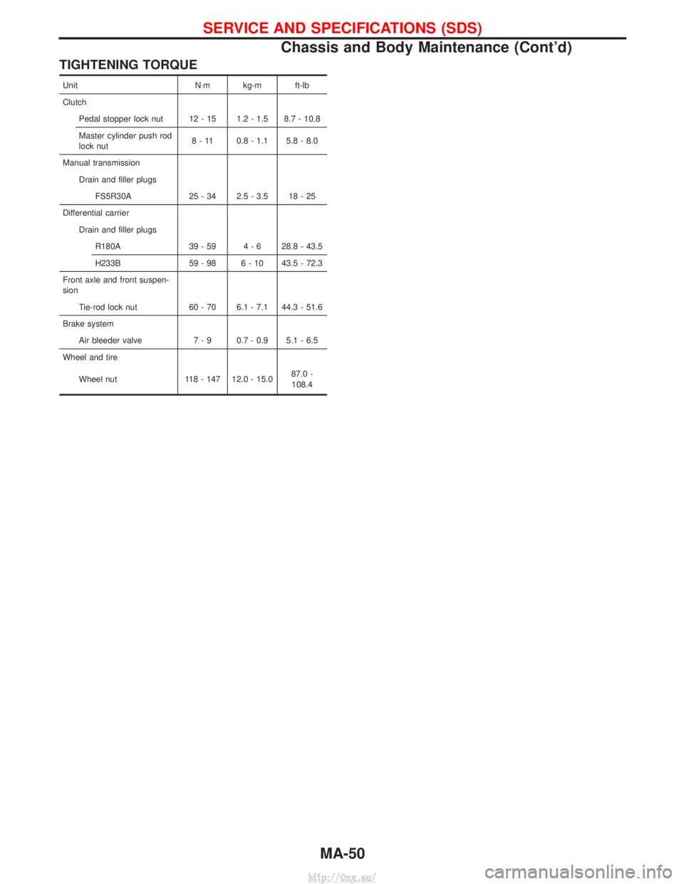
TIGHTENING TORQUE
UnitN×m kg-m ft-lb
Clutch Pedal stopper lock nut 12 - 15 1.2 - 1.5 8.7 - 10.8
Master cylinder push rod
lock nut 8 - 11 0.8 - 1.1 5.8 - 8.0
Manual transmission Drain and filler plugsFS5R30A 25 - 34 2.5 - 3.5 18 - 25
Differential carrier Drain and filler plugsR180A 39 - 59 4 - 6 28.8 - 43.5
H233B 59 - 98 6 - 10 43.5 - 72.3
Front axle and front suspen-
sion Tie-rod lock nut 60 - 70 6.1 - 7.1 44.3 - 51.6
Brake system Air bleeder valve 7 - 9 0.7 - 0.9 5.1 - 6.5
Wheel and tire
Wheel nut 118 - 147 12.0 - 15.0 87.0 -
108.4
SERVICE AND SPECIFICATIONS (SDS)
Chassis and Body Maintenance (Cont'd)
MA-50
http://vnx.su/