2004 NISSAN TERRANO locking
[x] Cancel search: lockingPage 6 of 1833

6. Before servicing the vehicle, protect fenders, upholstery andcarpeting with appropriate covers.
Take caution that keys, buckles or buttons on your person do
not scratch the paint.
7. Clean all disassembled parts in the designated liquid or solvent prior to inspection or assembly.
8. Replace oil seals, gaskets, packings, O-rings, locking washers, cotter pins, self-locking nuts, etc. with new ones.
9. Replace inner and outer races of tapered roller bearings and needle bearings as a set.
10. Arrange the disassembled parts in accordance with their assembled locations and sequence.
11. Do not touch the terminals of electrical components which use microcomputers (such as electronic control units).
Static electricity may damage internal electronic components.
12. After disconnecting vacuum or air hoses, attach a tag to indi- cate the proper connection.
13. Use only the lubricants specified in MA section.
14. Use approved bonding agent, sealants or their equivalents when required.
15. Use tools and recommended special tools where specified for safe and efficient service repairs.
16. When repairing the fuel, oil, water, vacuum or exhaust systems, check all affected lines for leaks.
17. Dispose of drained oil or the solvent used for cleaning parts in an appropriate manner.
Supplemental Restraint System (SRS) ªAIR
BAGº and ªSEAT BELT PRE-TENSIONERº
(Dual Air Bag System)
The Supplemental Restraint System ªAir Bagº and ªSeat Belt Pre-
tensionerº, used along with a seat belt, help to reduce the risk or
severity of injury to the driver and front passenger in a frontal col-
lision. The Supplemental Restraint System consists of air bag mod-
ules (located in the center of the steering wheel and on the instru-
ment panel on the passenger side), seat belt pre-tensioners, a
diagnosis sensor unit, warning lamp, wiring harness and spiral
cable.
WARNING:
ITo avoid rendering the SRS inoperative, which could
increase the risk of personal injury or death (in the event
of a collision which would result in air bag inflation), all
maintenance must be performed by an authorized NISSAN
dealer.
I Improper maintenance, including incorrect removal and
installation of the SRS, can lead to personal injury caused
by unintentional activation of the system.
I Do not use electrical test equipment on any circuit related
to the SRS unless instructed to do so in this Service
Manual. SRS wiring harnesses are covered with yellow
SGI234
SGI646
PRECAUTIONS
GI-3
http://vnx.su/
Page 395 of 1833
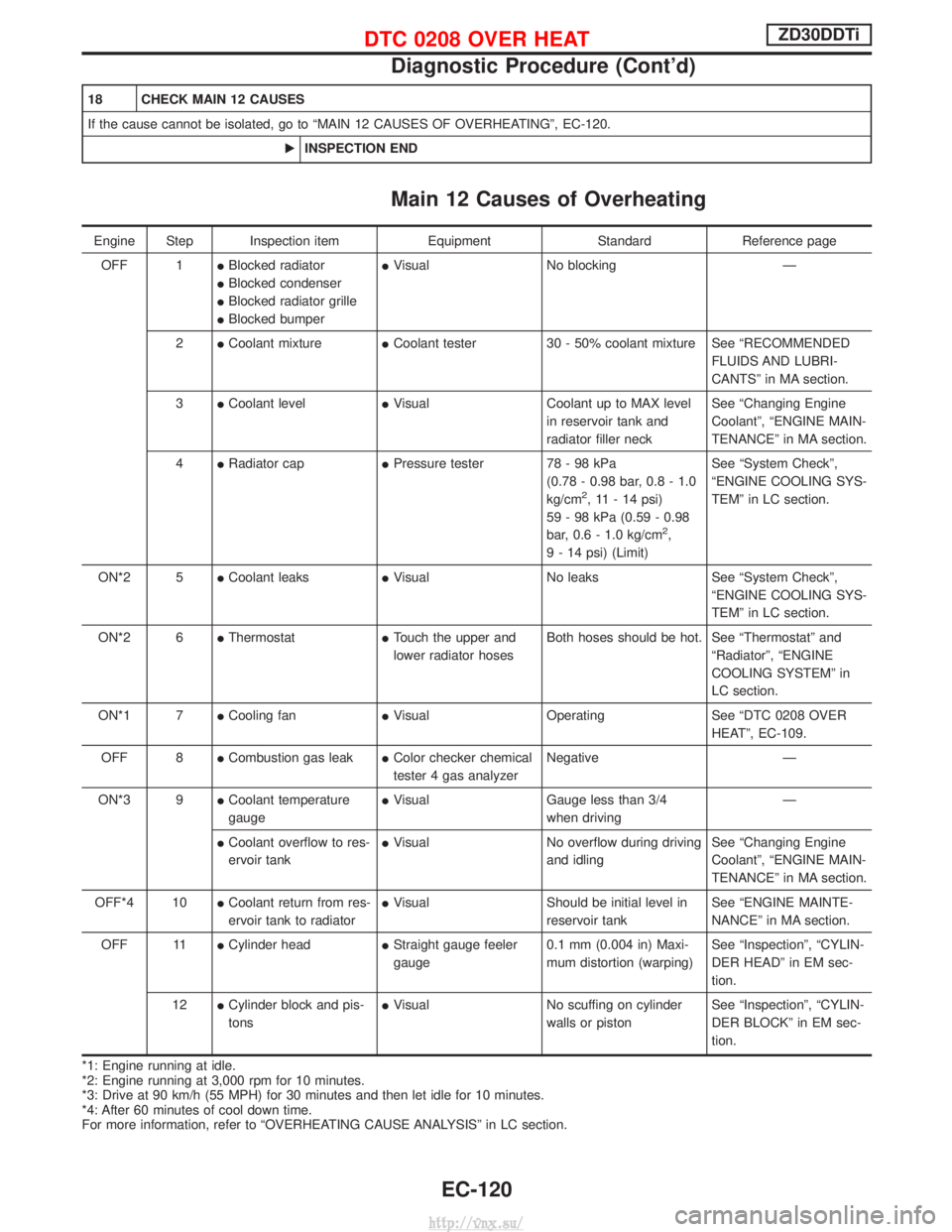
18 CHECK MAIN 12 CAUSES
If the cause cannot be isolated, go to ªMAIN 12 CAUSES OF OVERHEATINGº, EC-120.EINSPECTION END
Main 12 Causes of Overheating
Engine Step Inspection item EquipmentStandardReference page
OFF 1 IBlocked radiator
I Blocked condenser
I Blocked radiator grille
I Blocked bumper I
Visual No blocking Ð
2 ICoolant mixture ICoolant tester 30 - 50% coolant mixture See ªRECOMMENDED
FLUIDS AND LUBRI-
CANTSº in MA section.
3 ICoolant level IVisual Coolant up to MAX level
in reservoir tank and
radiator filler neck See ªChanging Engine
Coolantº, ªENGINE MAIN-
TENANCEº in MA section.
4 IRadiator cap IPressure tester 78 - 98 kPa
(0.78 - 0.98 bar, 0.8 - 1.0
kg/cm
2, 11 - 14 psi)
59 - 98 kPa (0.59 - 0.98
bar, 0.6 - 1.0 kg/cm
2,
9 - 14 psi) (Limit) See ªSystem Checkº,
ªENGINE COOLING SYS-
TEMº in LC section.
ON*2 5 ICoolant leaks IVisual No leaks See ªSystem Checkº,
ªENGINE COOLING SYS-
TEMº in LC section.
ON*2 6 IThermostat ITouch the upper and
lower radiator hoses Both hoses should be hot. See ªThermostatº and
ªRadiatorº, ªENGINE
COOLING SYSTEMº in
LC section.
ON*1 7 ICooling fan IVisual Operating See ªDTC 0208 OVER
HEATº, EC-109.
OFF 8 ICombustion gas leak IColor checker chemical
tester 4 gas analyzer Negative Ð
ON*3 9 ICoolant temperature
gauge I
Visual Gauge less than 3/4
when driving Ð
I Coolant overflow to res-
ervoir tank I
Visual No overflow during driving
and idling See ªChanging Engine
Coolantº, ªENGINE MAIN-
TENANCEº in MA section.
OFF*4 10 ICoolant return from res-
ervoir tank to radiator I
Visual Should be initial level in
reservoir tank See ªENGINE MAINTE-
NANCEº in MA section.
OFF 11 ICylinder head IStraight gauge feeler
gauge 0.1 mm (0.004 in) Maxi-
mum distortion (warping) See ªInspectionº, ªCYLIN-
DER HEADº in EM sec-
tion.
12 ICylinder block and pis-
tons I
Visual No scuffing on cylinder
walls or piston See ªInspectionº, ªCYLIN-
DER BLOCKº in EM sec-
tion.
*1: Engine running at idle.
*2: Engine running at 3,000 rpm for 10 minutes.
*3: Drive at 90 km/h (55 MPH) for 30 minutes and then let idle for 10 minutes.
*4: After 60 minutes of cool down time.
For more information, refer to ªOVERHEATING CAUSE ANALYSISº in LC section.
DTC 0208 OVER HEATZD30DDTi
Diagnostic Procedure (Cont'd)
EC-120
http://vnx.su/
Page 723 of 1833
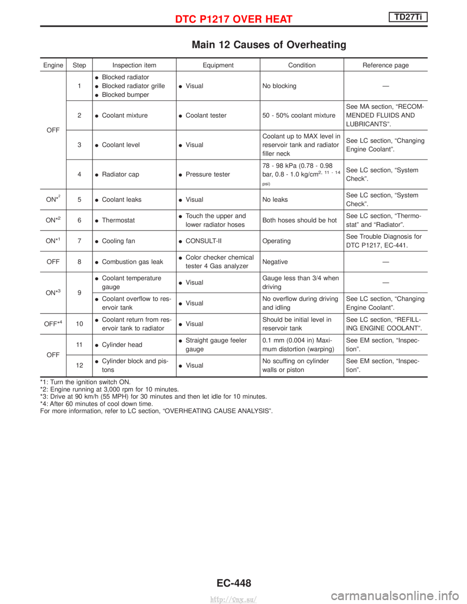
Main 12 Causes of Overheating
Engine Step Inspection itemEquipmentConditionReference page
OFF 1
I
Blocked radiator
I Blocked radiator grille
I Blocked bumper I
Visual No blocking Ð
2 ICoolant mixture ICoolant tester 50 - 50% coolant mixture See MA section, ªRECOM-
MENDED FLUIDS AND
LUBRICANTSº.
3 ICoolant level IVisual Coolant up to MAX level in
reservoir tank and radiator
filler neck See LC section, ªChanging
Engine Coolantº.
4 IRadiator cap IPressure tester 78 - 98 kPa (0.78 - 0.98
bar, 0.8 - 1.0 kg/cm
2,11-14
psi)See LC section, ªSystem
Checkº.
ON*
25 ICoolant leaks IVisual No leaks See LC section, ªSystem
Checkº.
ON*
26 IThermostat I
Touch the upper and
lower radiator hoses Both hoses should be hot See LC section, ªThermo-
statº and ªRadiatorº.
ON*
17 ICooling fan ICONSULT-II Operating See Trouble Diagnosis for
DTC P1217, EC-441.
OFF 8 ICombustion gas leak I
Color checker chemical
tester 4 Gas analyzer Negative Ð
ON*
39 I
Coolant temperature
gauge I
Visual Gauge less than 3/4 when
driving Ð
I Coolant overflow to res-
ervoir tank I
Visual No overflow during driving
and idling See LC section, ªChanging
Engine Coolantº.
OFF*
410 I
Coolant return from res-
ervoir tank to radiator I
Visual Should be initial level in
reservoir tank See LC section, ªREFILL-
ING ENGINE COOLANTº.
OFF 11
ICylinder head I
Straight gauge feeler
gauge 0.1 mm (0.004 in) Maxi-
mum distortion (warping) See EM section, ªInspec-
tionº.
12 I
Cylinder block and pis-
tons I
Visual No scuffing on cylinder
walls or piston See EM section, ªInspec-
tionº.
*1: Turn the ignition switch ON.
*2: Engine running at 3,000 rpm for 10 minutes.
*3: Drive at 90 km/h (55 MPH) for 30 minutes and then let idle for 10 minutes.
*4: After 60 minutes of cool down time.
For more information, refer to LC section, ªOVERHEATING CAUSE ANALYSISº.
DTC P1217 OVER HEATTD27Ti
EC-448
http://vnx.su/
Page 759 of 1833
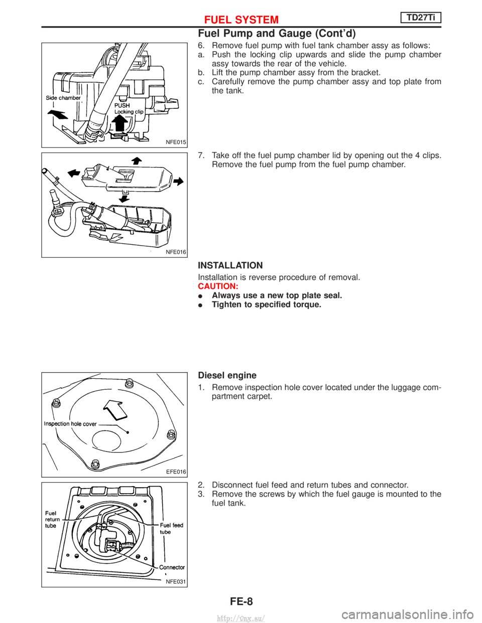
6. Remove fuel pump with fuel tank chamber assy as follows:
a. Push the locking clip upwards and slide the pump chamberassy towards the rear of the vehicle.
b. Lift the pump chamber assy from the bracket.
c. Carefully remove the pump chamber assy and top plate from the tank.
7. Take off the fuel pump chamber lid by opening out the 4 clips. Remove the fuel pump from the fuel pump chamber.
INSTALLATION
Installation is reverse procedure of removal.
CAUTION:
IAlways use a new top plate seal.
I Tighten to specified torque.
Diesel engine
1. Remove inspection hole cover located under the luggage com-
partment carpet.
2. Disconnect fuel feed and return tubes and connector.
3. Remove the screws by which the fuel gauge is mounted to the fuel tank.
NFE015
NFE016
EFE016
NFE031
FUEL SYSTEMTD27Ti
Fuel Pump and Gauge (Cont'd)
FE-8
http://vnx.su/
Page 1080 of 1833
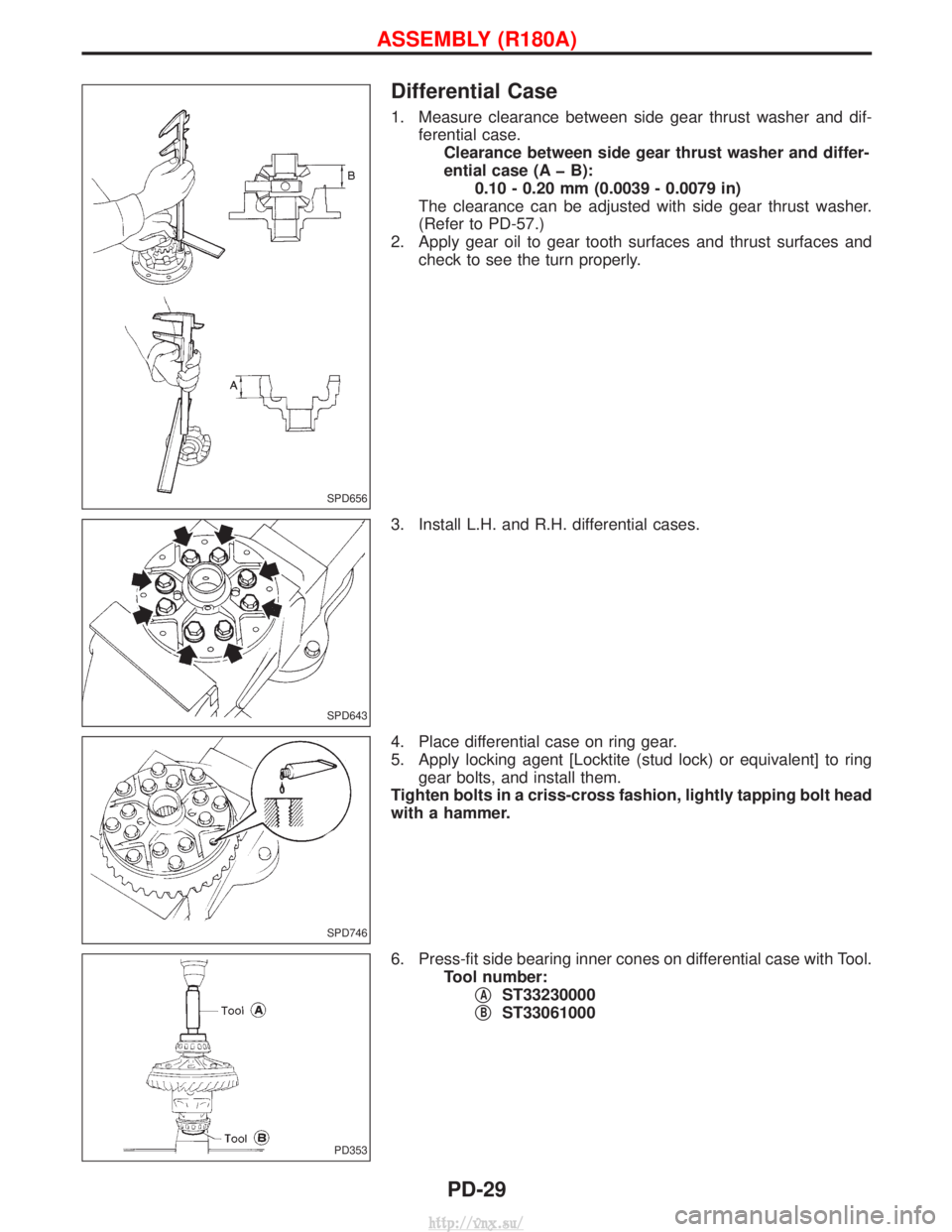
Differential Case
1. Measure clearance between side gear thrust washer and dif-ferential case.Clearance between side gear thrust washer and differ-
ential case (A þ B): 0.10 - 0.20 mm (0.0039 - 0.0079 in)
The clearance can be adjusted with side gear thrust washer.
(Refer to PD-57.)
2. Apply gear oil to gear tooth surfaces and thrust surfaces and check to see the turn properly.
3. Install L.H. and R.H. differential cases.
4. Place differential case on ring gear.
5. Apply locking agent [Locktite (stud lock) or equivalent] to ring gear bolts, and install them.
Tighten bolts in a criss-cross fashion, lightly tapping bolt head
with a hammer.
6. Press-fit side bearing inner cones on differential case with Tool. Tool number:q
AST33230000
q
BST33061000
SPD656
SPD643
SPD746
PD353
ASSEMBLY (R180A)
PD-29
http://vnx.su/
Page 1249 of 1833
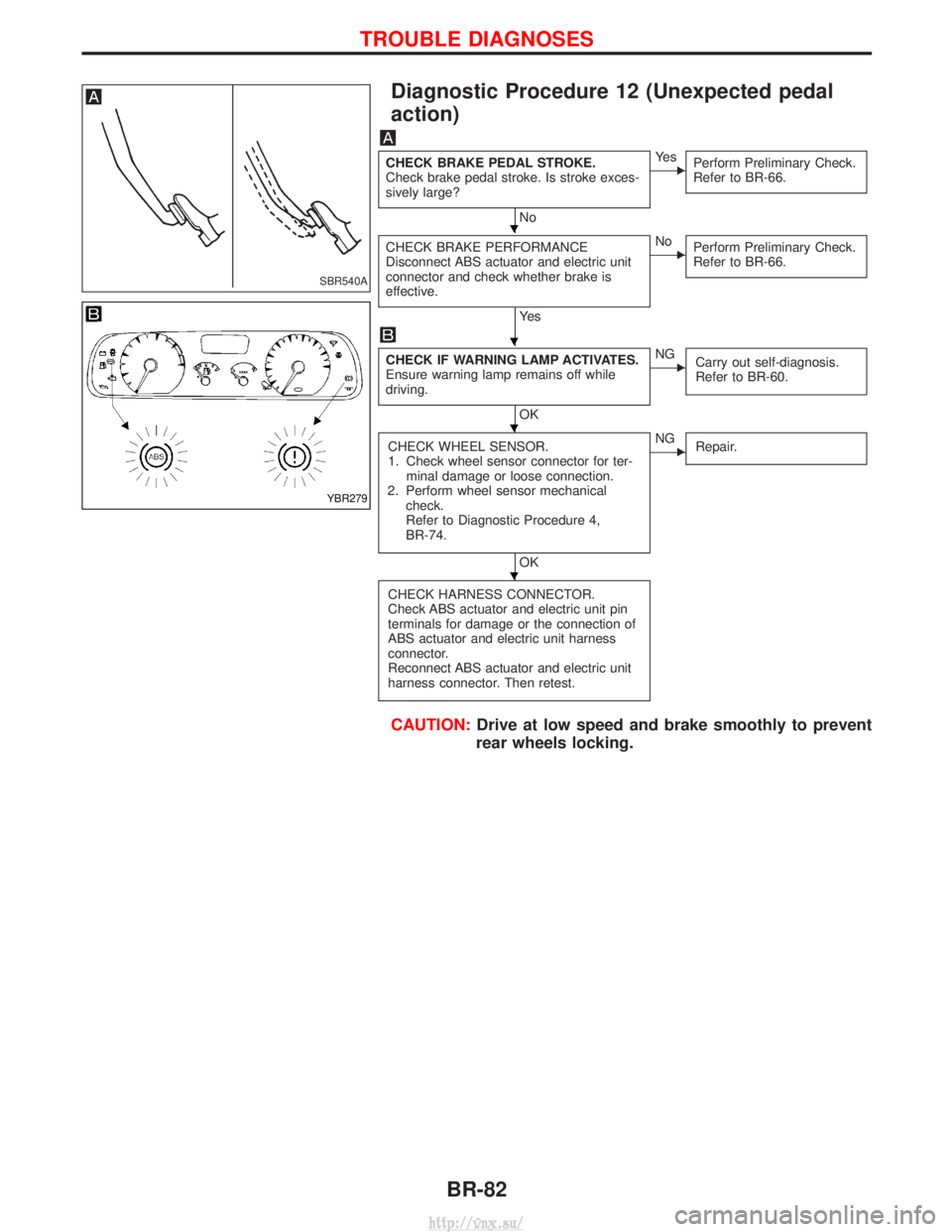
Diagnostic Procedure 12 (Unexpected pedal
action)
CHECK BRAKE PEDAL STROKE.
Check brake pedal stroke. Is stroke exces-
sively large?
No
EYe sPerform Preliminary Check.
Refer to BR-66.
CHECK BRAKE PERFORMANCE
Disconnect ABS actuator and electric unit
connector and check whether brake is
effective.
Ye s
ENoPerform Preliminary Check.
Refer to BR-66.
CHECK IF WARNING LAMP ACTIVATES.
Ensure warning lamp remains off while
driving.
OK
ENG
Carry out self-diagnosis.
Refer to BR-60.
CHECK WHEEL SENSOR.
1. Check wheel sensor connector for ter-
minal damage or loose connection.
2. Perform wheel sensor mechanical check.
Refer to Diagnostic Procedure 4,
BR-74.
OK
ENG Repair.
CHECK HARNESS CONNECTOR.
Check ABS actuator and electric unit pin
terminals for damage or the connection of
ABS actuator and electric unit harness
connector.
Reconnect ABS actuator and electric unit
harness connector. Then retest.
CAUTION: Drive at low speed and brake smoothly to prevent
rear wheels locking.
SBR540A
YBR279
H
H
H
H
TROUBLE DIAGNOSES
BR-82
http://vnx.su/
Page 1292 of 1833
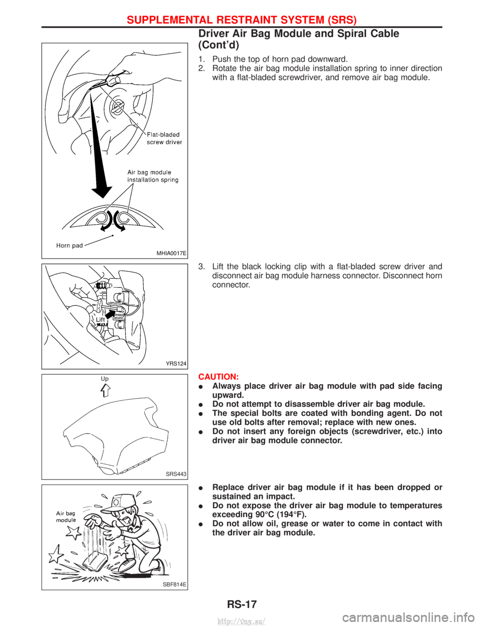
1. Push the top of horn pad downward.
2. Rotate the air bag module installation spring to inner directionwith a flat-bladed screwdriver, and remove air bag module.
3. Lift the black locking clip with a flat-bladed screw driver and disconnect air bag module harness connector. Disconnect horn
connector.
CAUTION:
I Always place driver air bag module with pad side facing
upward.
I Do not attempt to disassemble driver air bag module.
I The special bolts are coated with bonding agent. Do not
use old bolts after removal; replace with new ones.
I Do not insert any foreign objects (screwdriver, etc.) into
driver air bag module connector.
I Replace driver air bag module if it has been dropped or
sustained an impact.
I Do not expose the driver air bag module to temperatures
exceeding 90ÉC (194ÉF).
I Do not allow oil, grease or water to come in contact with
the driver air bag module.
MHIA0017E
YRS124
SRS443
SBF814E
SUPPLEMENTAL RESTRAINT SYSTEM (SRS)
Driver Air Bag Module and Spiral Cable
(Cont'd)
RS-17
http://vnx.su/
Page 1294 of 1833
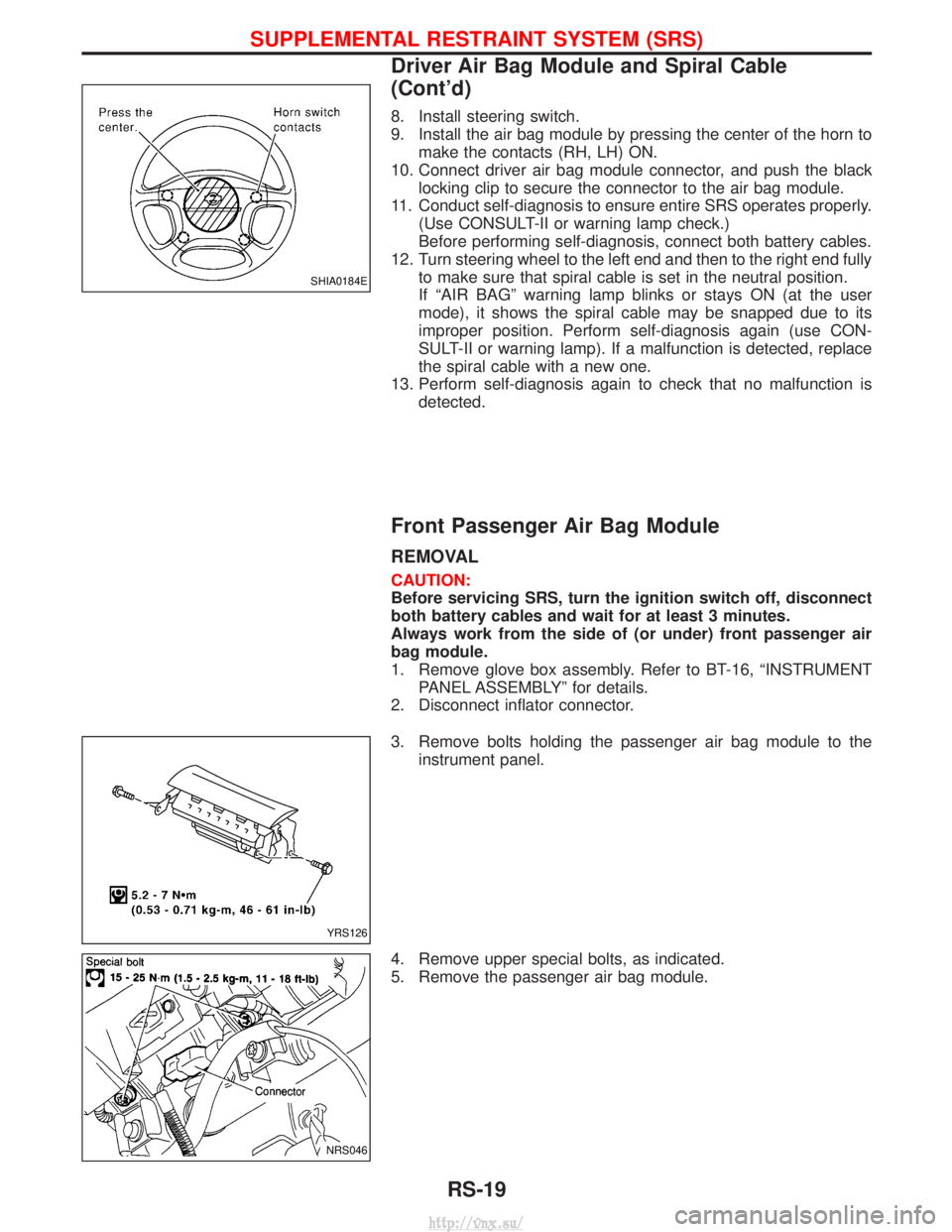
8. Install steering switch.
9. Install the air bag module by pressing the center of the horn tomake the contacts (RH, LH) ON.
10. Connect driver air bag module connector, and push the black locking clip to secure the connector to the air bag module.
11. Conduct self-diagnosis to ensure entire SRS operates properly. (Use CONSULT-II or warning lamp check.)
Before performing self-diagnosis, connect both battery cables.
12. Turn steering wheel to the left end and then to the right end fully to make sure that spiral cable is set in the neutral position.
If ªAIR BAGº warning lamp blinks or stays ON (at the user
mode), it shows the spiral cable may be snapped due to its
improper position. Perform self-diagnosis again (use CON-
SULT-II or warning lamp). If a malfunction is detected, replace
the spiral cable with a new one.
13. Perform self-diagnosis again to check that no malfunction is detected.
Front Passenger Air Bag Module
REMOVAL
CAUTION:
Before servicing SRS, turn the ignition switch off, disconnect
both battery cables and wait for at least 3 minutes.
Always work from the side of (or under) front passenger air
bag module.
1. Remove glove box assembly. Refer to BT-16, ªINSTRUMENTPANEL ASSEMBLYº for details.
2. Disconnect inflator connector.
3. Remove bolts holding the passenger air bag module to the instrument panel.
4. Remove upper special bolts, as indicated.
5. Remove the passenger air bag module.
SHIA0184E
YRS126
NRS046
SUPPLEMENTAL RESTRAINT SYSTEM (SRS)
Driver Air Bag Module and Spiral Cable
(Cont'd)
RS-19
http://vnx.su/