2004 NISSAN TERRANO seat adjustment
[x] Cancel search: seat adjustmentPage 92 of 1833
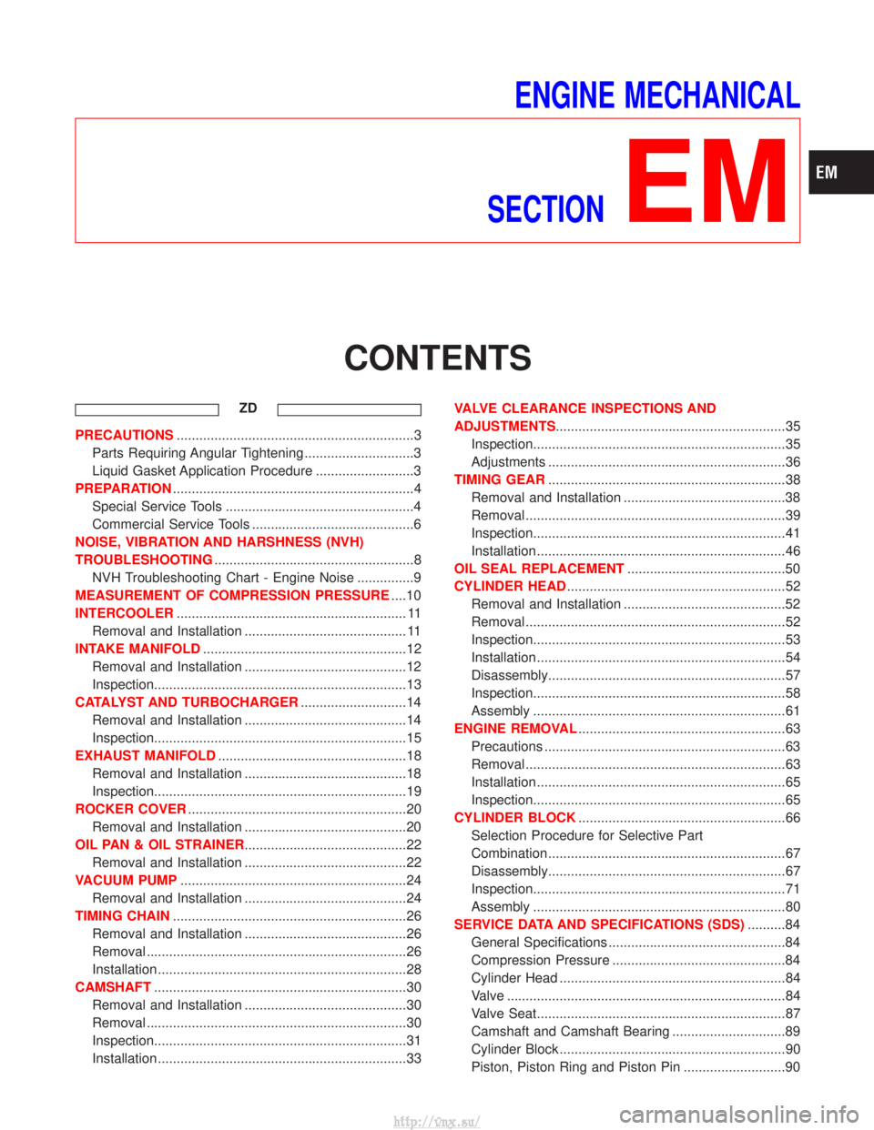
ENGINE MECHANICAL
SECTION
EM
CONTENTS
ZD
PRECAUTIONS ...............................................................3
Parts Requiring Angular Tightening .............................3
Liquid Gasket Application Procedure ..........................3
PREPARATION ................................................................4
Special Service Tools ..................................................4
Commercial Service Tools ...........................................6
NOISE, VIBRATION AND HARSHNESS (NVH)
TROUBLESHOOTING .....................................................8
NVH Troubleshooting Chart - Engine Noise ...............9
MEASUREMENT OF COMPRESSION PRESSURE ....10
INTERCOOLER ............................................................. 11
Removal and Installation ........................................... 11
INTAKE MANIFOLD ......................................................12
Removal and Installation ...........................................12
Inspection...................................................................13
CATALYST AND TURBOCHARGER ............................14
Removal and Installation ...........................................14
Inspection...................................................................15
EXHAUST MANIFOLD ..................................................18
Removal and Installation ...........................................18
Inspection...................................................................19
ROCKER COVER ..........................................................20
Removal and Installation ...........................................20
OIL PAN & OIL STRAINER ...........................................22
Removal and Installation ...........................................22
VACUUM PUMP ............................................................24
Removal and Installation ...........................................24
TIMING CHAIN ..............................................................26
Removal and Installation ...........................................26
Removal .....................................................................26
Installation ..................................................................28
CAMSHAFT ...................................................................30
Removal and Installation ...........................................30
Removal .....................................................................30
Inspection...................................................................31
Installation ..................................................................33 VALVE CLEARANCE INSPECTIONS AND
ADJUSTMENTS
.............................................................35
Inspection...................................................................35
Adjustments ...............................................................36
TIMING GEAR ...............................................................38
Removal and Installation ...........................................38
Removal .....................................................................39
Inspection...................................................................41
Installation ..................................................................46
OIL SEAL REPLACEMENT ..........................................50
CYLINDER HEAD ..........................................................52
Removal and Installation ...........................................52
Removal .....................................................................52
Inspection...................................................................53
Installation ..................................................................54
Disassembly...............................................................57
Inspection...................................................................58
Assembly ...................................................................61
ENGINE REMOVAL .......................................................63
Precautions ................................................................63
Removal .....................................................................63
Installation ..................................................................65
Inspection...................................................................65
CYLINDER BLOCK .......................................................66
Selection Procedure for Selective Part
Combination ...............................................................67
Disassembly...............................................................67
Inspection...................................................................71
Assembly ...................................................................80
SERVICE DATA AND SPECIFICATIONS (SDS) ..........84
General Specifications ...............................................84
Compression Pressure ..............................................84
Cylinder Head ............................................................84
Valve ........................................................................\
..84
Valve Seat..................................................................87
Camshaft and Camshaft Bearing ..............................89
Cylinder Block ............................................................90
Piston, Piston Ring and Piston Pin ...........................90
http://vnx.su/
Page 206 of 1833
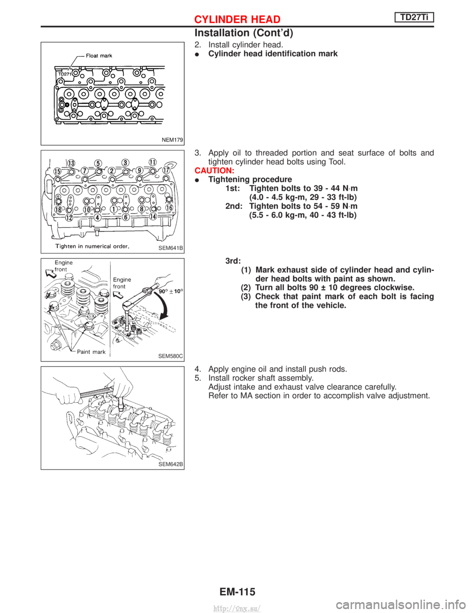
2. Install cylinder head.
ICylinder head identification mark
3. Apply oil to threaded portion and seat surface of bolts and tighten cylinder head bolts using Tool.
CAUTION:
I Tightening procedure
1st: Tighten bolts to 39 - 44 N×m (4.0 - 4.5 kg-m, 29 - 33 ft-lb)
2nd: Tighten bolts to 54 - 59 N ×m
(5.5 - 6.0 kg-m, 40 - 43 ft-lb)
3rd: (1) Mark exhaust side of cylinder head and cylin-der head bolts with paint as shown.
(2) Turn all bolts 90 10 degrees clockwise.
(3) Check that paint mark of each bolt is facing the front of the vehicle.
4. Apply engine oil and install push rods.
5. Install rocker shaft assembly. Adjust intake and exhaust valve clearance carefully.
Refer to MA section in order to accomplish valve adjustment.
NEM179
SEM641B
SEM580C
SEM642B
CYLINDER HEADTD27Ti
Installation (Cont'd)
EM-115
http://vnx.su/
Page 236 of 1833
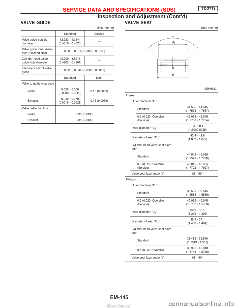
VALVE GUIDE
Unit: mm (in)
StandardService
Valve guide outside
diameter 12.233 - 12.244
(0.4816 - 0.4820) Ð
Valve guide inner diam-
eter (Finished size) 8.000 - 8.015 (0.3150 - 0.3156)
Cylinder head valve
guide hole diameter 12.200 - 12.211
(0.4803 - 0.4807) Ð
Interference fit of valve
guide 0.022 - 0.044 (0.0009 - 0.0017)
Standard Limit
Valve to guide clearance
Intake 0.020 - 0.050
(0.0008 - 0.0020) 0.15 (0.0059)
Exhaust 0.040 - 0.070
(0.0016 - 0.0028) 0.15 (0.0059)
Valve deflection limit Intake 0.35 (0.0138)
Exhaust 0.35 (0.0138)
VA LV E S E AT
Unit: mm (in)
SEM953C
Intake
Outer diameter ªD
1º
Standard 44.535 - 44.545
(1.7533 - 1.7537)
0.5 (0.020) Oversize
(Service) 45.035 - 45.045
(1.7730 - 1.7734)
Inner diameter ªD
2º 38.0 0.1
(1.50 0.0039)
Diameter of seat ªD
3º 42.4 - 42.6
(1.669 - 1.677)
Cylinder head valve seat diam-
eter
Standard 44.515 - 45.035
(1.7526 - 1.7730)
0.5 (0.020) Oversize
(Service) 45.015 - 45.535
(1.7722 - 1.7927)
Valve seat face angle ªf º89 - 90É
Exhaust Outer diameter ªD
1º
Standard 39.535 - 39.545
(1.5565 - 1.5569)
0.5 (0.020) Oversize
(Service) 40.035 - 40.045
(1.5762 - 1.5766)
Inner diameter ªD
2º 32.9 - 33.1
(1.295 - 1.303)
Diameter of seat ªD
3º 36.9 - 37.1
(1.453 - 1.461)
Cylinder head valve seat diam-
eter
Standard 39.495 - 39.510
(1.5549 - 1.555)
0.5 (0.020) Oversize 39.995 - 40.010
(1.5746 - 1.5758)
Valve seat face angle ªf º89 - 90É
SERVICE DATA AND SPECIFICATIONS (SDS)TD27Ti
Inspection and Adjustment (Cont'd)
EM-145
http://vnx.su/
Page 237 of 1833
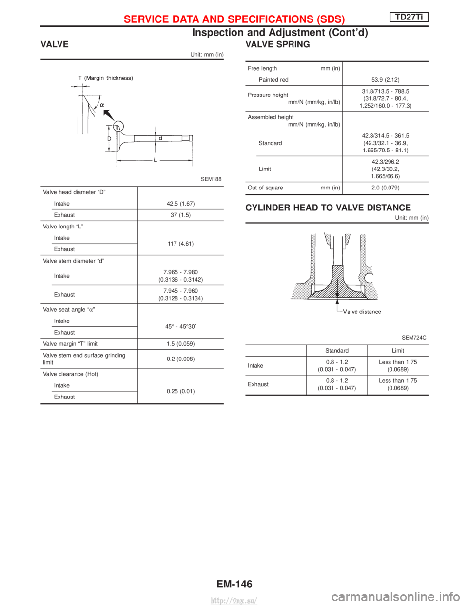
VA LV E
Unit: mm (in)
SEM188
Valve head diameter ªDºIntake 42.5 (1.67)
Exhaust 37 (1.5)
Valve length ªLº Intake 117 (4.61)
Exhaust
Valve stem diameter ªdº
Intake 7.965 - 7.980
(0.3136 - 0.3142)
Exhaust 7.945 - 7.960
(0.3128 - 0.3134)
Valve seat angle ªa º
Intake 45É - 45É30¢
Exhaust
Valve margin ªTº limit 1.5 (0.059)
Valve stem end surface grinding
limit 0.2 (0.008)
Valve clearance (Hot) Intake 0.25 (0.01)
Exhaust
VALVE SPRING
Free length mm (in)
Painted red 53.9 (2.12)
Pressure height mm/N (mm/kg, in/lb) 31.8/713.5 - 788.5
(31.8/72.7 - 80.4,
1.252/160.0 - 177.3)
Assembled height mm/N (mm/kg, in/lb)
Standard 42.3/314.5 - 361.5
(42.3/32.1 - 36.9,
1.665/70.5 - 81.1)
Limit 42.3/296.2
(42.3/30.2,
1.665/66.6)
Out of square mm (in)2.0 (0.079)
CYLINDER HEAD TO VALVE DISTANCE
Unit: mm (in)
SEM724C
Standard Limit
Intake 0.8 - 1.2
(0.031 - 0.047) Less than 1.75
(0.0689)
Exhaust 0.8 - 1.2
(0.031 - 0.047) Less than 1.75
(0.0689)
SERVICE DATA AND SPECIFICATIONS (SDS)TD27Ti
Inspection and Adjustment (Cont'd)
EM-146
http://vnx.su/
Page 1076 of 1833
![NISSAN TERRANO 2004 Service Repair Manual 3. Measure how far under the standard thickness [20 mm (0.79in)] the side bearings are.
It will require tools shown below.
q
1Weight Block (ST32501000)
q
2Master Gauge (KV38101900)
q
3Base Plate
q
4Di NISSAN TERRANO 2004 Service Repair Manual 3. Measure how far under the standard thickness [20 mm (0.79in)] the side bearings are.
It will require tools shown below.
q
1Weight Block (ST32501000)
q
2Master Gauge (KV38101900)
q
3Base Plate
q
4Di](/manual-img/5/57394/w960_57394-1075.png)
3. Measure how far under the standard thickness [20 mm (0.79in)] the side bearings are.
It will require tools shown below.
q
1Weight Block (ST32501000)
q
2Master Gauge (KV38101900)
q
3Base Plate
q
4Dial Indicator
4. Place the outer race of the opposite side bearing to the mea- sured.
5. Place a weight block on the outer race, and a master gauge on the block.Tool number: q
AST32501000
q
BKV38101900
6. Adjust dial indicator scale to zero.
7. Carefully slide master gauge and weight block out from under dial indicator.
8. Lubricate side bearing and place the bearing outer race and inner cone to be measured on the opposite side outer race.
If the bearing assembly is placed on the base plate, the bear-
ing width cannot be accurately determined due to its cage
being in contact with the base plate.
9. Place weight block (ST32501000) on side bearing.
10. Slide dial indicator on weight block.
11. Turn weight block a few times to ensure that bearing is prop- erly seated.
12. Read dial indicator.
I Normal indication:
0.10 - 0.30 mm (0.0039 - 0.0118 in)
I If the needle fluctuates erratically then bearing is either dirty or
defective and should be cleaned or replaced.
SPD048
SPD150
SPD050
SPD591
SPD051
ADJUSTMENT (R180A)
Side Bearing Preload (Cont'd)
PD-25
http://vnx.su/
Page 1088 of 1833
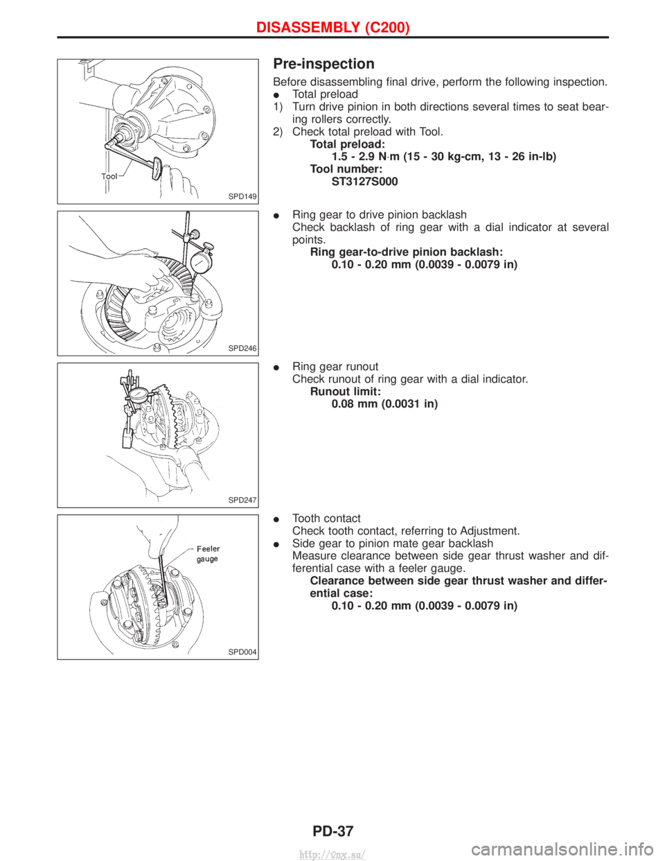
Pre-inspection
Before disassembling final drive, perform the following inspection.
ITotal preload
1) Turn drive pinion in both directions several times to seat bear- ing rollers correctly.
2) Check total preload with Tool. Total preload:1.5 - 2.9 N ×m (15 - 30 kg-cm, 13 - 26 in-lb)
Tool number: ST3127S000
I Ring gear to drive pinion backlash
Check backlash of ring gear with a dial indicator at several
points.
Ring gear-to-drive pinion backlash: 0.10 - 0.20 mm (0.0039 - 0.0079 in)
I Ring gear runout
Check runout of ring gear with a dial indicator.
Runout limit: 0.08 mm (0.0031 in)
I Tooth contact
Check tooth contact, referring to Adjustment.
I Side gear to pinion mate gear backlash
Measure clearance between side gear thrust washer and dif-
ferential case with a feeler gauge.
Clearance between side gear thrust washer and differ-
ential case: 0.10 - 0.20 mm (0.0039 - 0.0079 in)
SPD149
SPD246
SPD247
SPD004
DISASSEMBLY (C200)
PD-37
http://vnx.su/
Page 1118 of 1833
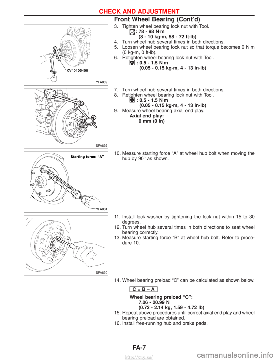
3. Tighten wheel bearing lock nut with Tool.
:78-98N×m
(8 - 10 kg-m, 58 - 72 ft-lb)
4. Turn wheel hub several times in both directions.
5. Loosen wheel bearing lock nut so that torque becomes 0 N ×m
(0 kg-m, 0 ft-lb).
6. Retighten wheel bearing lock nut with Tool.
: 0.5 - 1.5 N ×m
(0.05 - 0.15 kg-m,4-13 in-lb)
7. Turn wheel hub several times in both directions.
8. Retighten wheel bearing lock nut with Tool.
: 0.5 - 1.5 N ×m
(0.05 - 0.15 kg-m,4-13 in-lb)
9. Measure wheel bearing axial end play. Axial end play:0mm(0in)
10. Measure starting force ªAº at wheel hub bolt when moving the hub by 90É as shown.
11. Install lock washer by tightening the lock nut within 15 to 30 degrees.
12. Turn wheel hub several times in both directions to seat wheel bearing correctly.
13. Measure starting force ªBº at wheel hub bolt. Refer to proce- dure 10.
14. Wheel bearing preload ªCº can be calculated as shown below. C=BþA
Wheel bearing preload ªCº:7.06 - 20.99 N
(0.72 - 2.14 kg, 1.59 - 4.72 lb)
15. Repeat above procedures until correct axial end play and wheel bearing preload are obtained.
16. Install free-running hub and brake pads.
YFA009
SFA892
YFA004
SFA830
CHECK AND ADJUSTMENT
Front Wheel Bearing (Cont'd)
FA-7
http://vnx.su/
Page 1168 of 1833
BRAKE SYSTEM
SECTION
BR
CONTENTS
PRECAUTIONS AND PREPARATION ............................3
Supplement Restraint System (SRS) ²AIR BAG²
and ²SEAT BELT PRE-TENSIONER² .........................3
Precautions ..................................................................3
Preparation ..................................................................4
CHECK AND ADJUSTMENT ..........................................5
Checking Brake Fluid Level.........................................5
Checking Brake Line ...................................................5
Changing Brake Fluid ..................................................5
Brake Burnishing Procedure........................................5
BRAKE HYDRAULIC LINE .............................................6
Bleeding Brake System ...............................................8
Removal .......................................................................9
Inspection.....................................................................9
Installation ....................................................................9
LOAD SENSING VALVE ...............................................10
Removal and Installation ...........................................10
Removal ..................................................................... 11
Installation .................................................................. 11
Inspection and Adjustment ........................................12
BRAKE PEDAL AND BRACKET ..................................14
Removal and Installation ...........................................14
Removal .....................................................................15
Installation ..................................................................15
Inspection...................................................................15
Adjustment .................................................................16
MASTER CYLINDER .....................................................17
Removal .....................................................................17
Installation ..................................................................17
BRAKE BOOSTER ........................................................18
Removal and Installation ...........................................18
Inspection...................................................................18
Installation ..................................................................19
VACUUM HOSE .............................................................20
Removal and Installation ...........................................20
Inspection...................................................................22
VACUUM PUMP (TD27Ti engine model) ....................24
Removal and Installation ...........................................24
Inspection...................................................................24 VACUUM PUMP (ZD30DDTi engine model)
...............26
Removal and Installation ...........................................26
FRONT DISC BRAKE ...................................................27
Pad Replacement ......................................................27
Removal .....................................................................28
Disassembly...............................................................28
Inspection...................................................................28
Assembly ...................................................................29
Inspection...................................................................29
Installation ..................................................................31
REAR DRUM BRAKE ...................................................32
Removal .....................................................................33
Shoe Replacement ....................................................34
Inspection...................................................................34
Installation ..................................................................34
PARKING BRAKE CONTROL ......................................36
Removal and Installation ...........................................36
Inspection...................................................................36
Adjustment .................................................................36
ANTI-LOCK BRAKE SYSTEM ......................................38
Purpose......................................................................38
Operation ...................................................................38
ABS Hydraulic Circuit ................................................38
System Description ....................................................39
Removal and Installation ...........................................43
TROUBLE DIAGNOSES ...............................................48
How to Perform Trouble Diagnoses for Quick
and Accurate Repair ..................................................48
Component Parts and Harness Connector
Location .....................................................................49
Circuit Diagram for Quick Pinpoint Check.................50
Wiring Diagram - ABS - .............................................51
CONSULT-II ...............................................................59
CONSULT-II Inspection Procedure............................60
Preliminary Check......................................................66
Ground Circuit Check ................................................67
Diagnostic Procedure 1 (Not self-diagnostic item) ....68
Diagnostic Procedure 2 (Warning lamp stays on
when ignition switch is turned ON)............................70
http://vnx.su/