Page 64 of 1833

12. Fill reservoir tank up to ªMAXº level, and re-install radiator cap.
13. Run the engine at approximately 2,000 rpm for about oneminute.
14. Stop engine and cool it down, then refill the radiator and the reservoir tank up to the specified level.
Checking Cooling System
CHECKING HOSES
Check hoses for proper attachment, leaks, cracks, damage, loose
connections, chafing and deterioration.
CHECKING RADIATOR CAP
Apply pressure to radiator cap by means of a cap tester to see if it
is satisfactory. Radiator cap relief pressure:78-98kPa
(0.78 - 0.98 bar, 0.8 - 1.0 kg/cm
2, 11 - 14 psi)
CHECKING COOLING SYSTEM FOR LEAKS
Apply pressure to the cooling system by means of a tester to check
for leakage. Testing pressure:157 kPa (1.57 bar, 1.6 kg/cm
2, 23 psi)
CAUTION:
Higher than the specified pressure may cause radiator dam-
age.
Checking and Replacing fuel filter and Draining
Water
Be careful not to spill fuel in engine compartment. Place a rag
to absorb fuel.
REPLACING FUEL FILTER
1. Remove fuel filter sensor and drain fuel.
YMA008
SLC613
SMA990A
NMA009
ENGINE MAINTENANCETD
Changing Engine Coolant (Cont'd)
MA-23
http://vnx.su/
Page 66 of 1833

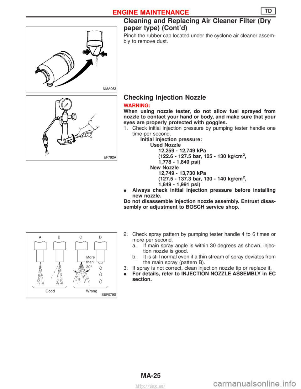
Pinch the rubber cap located under the cyclone air cleaner assem-
bly to remove dust.
Checking Injection Nozzle
WARNING:
When using nozzle tester, do not allow fuel sprayed from
nozzle to contact your hand or body, and make sure that your
eyes are properly protected with goggles.
1. Check initial injection pressure by pumping tester handle onetime per second.Initial injection pressure: Used Nozzle12,259 - 12,749 kPa
(122.6 - 127.5 bar, 125 - 130 kg/cm
2,
1,778 - 1,849 psi)
New Nozzle 12,749 - 13,730 kPa
(127.5 - 137.3 bar, 130 - 140 kg/cm
2,
1,849 - 1,991 psi)
I Always check initial injection pressure before installing
new nozzle.
Do not disassemble injection nozzle assembly. Entrust disas-
sembly or adjustment to BOSCH service shop.
2. Check spray pattern by pumping tester handle 4 to 6 times or more per second.
a. If main spray angle is within 30 degrees as shown, injec- tion nozzle is good.
b. It is still normal even if a thin stream of spray deviates from the main spray (pattern B).
3. If spray is not correct, clean injection nozzle tip or replace it.
I For details, refer to INJECTION NOZZLE ASSEMBLY in EC
section.
NMA063
EF792A
SEF079S
ENGINE MAINTENANCETD
Cleaning and Replacing Air Cleaner Filter (Dry
paper type) (Cont'd)
MA-25
http://vnx.su/
Page 67 of 1833

Checking Idle Speed
Preparation
1. Make sure that injection timing is correct.
2. Make sure that injection nozzle are in good condition.
3. Make sure that the following parts are in good condition.
IAir cleaner clogging
I Glow system
I Engine oil and coolant levels
I Valve clearance
I Air intake system (Oil filler cap, oil level gauge, etc.)
4. Set shift lever in ªNeutralº position. Engage parking brake and lock both front and rear wheels with wheel chocks.
5. Turn off air conditioner, lights and accessories.
I Warm up engine until water temperature indicator points to middle of gauge.
I Lights, heater fan and all accessories are off.
I Attach tachometer's pick-up to No. 1 fuel injection tube.
In order to take accurate reading of engine rpm, remove clamps that secure No. 1 fuel injection tube.
Start engine.
SMA406B
SMA021A
Run engine at about 2,000 rpm for
about 2 minutes under no-load.
Run engine for one minute at idle
speed.F
Check idle speed.
---------------------------------------------------------------------------------------------------------------------------------------------------------------------------------------------------------------------------------- IDLE SPEED: 700+ 50 rpm
OK
ENG Adjust idle speed by turning idle speed adjust-
ing screw.
EMA049
END
I
Race engine two or three times and allow engine to return to idle speed. If idle speed is not within
the specified range, check acceleration linkage for binding and correct it if necessary.
H
H
H
H
H
ENGINE MAINTENANCETD
MA-26
http://vnx.su/
Page 74 of 1833

CHECKING RADIATOR CAP
Apply pressure to radiator cap (side with pressure valve) with cap
tester to see if it is satisfactory.Radiator cap relief pressure:108 - 128 kPa
(1.08 - 1.28 bar, 1.1 - 1.3 kg/cm
2, 16 - 18 psi)
Pull the negative-pressure valve to open it. Check that it closes
completely when released.
CHECKING COOLING SYSTEM FOR LEAKS
Apply pressure to the cooling system with cap tester to check for
leakage. Testing pressure:157 kPa (1.57 bar, 1.6 kg/cm
2, 23 psi)
CAUTION:
Use of higher pressure than the specified value may cause
damage to radiator.
Checking and Replacing Fuel Filter and
Draining Water
Be careful not to spill fuel in engine compartment. Place a rag
to absorb fuel.
CHECKING FUEL FILTER
Check fuel filter for fuel leakage, damage and other abnormal
signs.
REPLACING FUEL FILTER
1. Disconnect harness connector and drain fuel.
2. Remove fuel filter using band-type filter wrench.
3. Remove fuel filter and fuel filter sensor.
CAUTION:
Remove fuel filter without spilling fuel. If spilt, wipe off imme-
diately. Be specially careful not to spill fuel on engine mount
insulator.
SLC613
SMA871B
JMA110D
DMA011
SMA111D
ENGINE MAINTENANCEZD
Checking Cooling System (Cont'd)
MA-33
http://vnx.su/
Page 155 of 1833

Engine room (Left)
3. Remove air duct and air cleaner case.
4. Disconnect vacuum hose to the vehicle on the engine.
5. Disconnect harness connectors from alternator and air com-pressor.
6. Remove alternator.
7. After removing refrigerant, remove pipes of air compressor and inlet/outlet.
8. Disconnect heating hose, install blank cap to hose to prevent coolant from leaking.
9. Remove heating pipe.
10. Remove heat insulator.
11. Remove catalytic converter.
Engine room (Right)
12. Remove power steering reservoir tank from bracket, and fix it to the vehicle with a rope.
CAUTION:
Keep the reservoir tank level when fixing to prevent oil leak.
13. Remove fuel feed and return hoses.
CAUTION:
Install blank caps immediately to avoid fuel leakage.
14. Remove all harness connectors on the engine, and move har- nesses to the side of the vehicle.
Vehicle underfloor
15. Remove starter motor.
16. Detach A/T oil cooler pipes from oil pan. (A/T model)
17. Remove rear propeller shaft.
18. Remove mounting bolts to secure the engine to transmission.
1) Remove torque converter installation bolt. (A/T model)
2) Lift transmission bottom with transmission jack, and removerear mount members from the vehicle.
3) Lower transmission with the jack, and remove upper mounting bolts securing the engine to transmission.
4) Lift transmission with the jack, and reinstall rear mount mem- bers to the vehicle.
5) Position the jack to the front side of transmission.
6) Remove remaining mounting bolts securing the engine to trans- mission.
Removal operation
19. Remove air conditioner high pressure pipes at the rear of theengine room.
I This is due to some inconvenience in the rear slinger installa-
tion.
20. Install the engine slingers (standard service part) to front-left and rear-right.
:25-28N ×m (2.5 - 2.9 kg-m, 18 - 20 ft-lb)
WARNING:
For engines without engine slingers, attach proper slingers
and bolts described in the PARTS CATALOG.
FEM082
ENGINE REMOVALZD
Removal (Cont'd)
EM-64
http://vnx.su/
Page 231 of 1833
2. Install pistons with connecting rods.
(1) Install them into corresponding cylinder using Tool.
IBe careful not to scratch cylinder wall with connecting rod.
I Apply engine oil to cylinder wall, piston and bearing.
I The leaf type combustion chamber on piston head must be
facing toward the fuel pump side.
(2) Install connecting rod bearing caps.
3. Measure connecting rod side clearance. Connecting rod side clearance:Standard0.10 - 0.32 mm (0.0039 - 0.0126 in)
Limit 0.32 mm (0.0126 in)
If beyond the limit, replace connecting rod and/or crankshaft.
4. Install oil strainer and oil pan.
5. Install all removed parts.
GEAR TRAIN
1. Set No. 1 piston at its Top Dead Center.
2. Align each gear mark and install gears.
EEM108
SEM678B
SEM488
NEM177
ENGINE OVERHAULTD27Ti
Assembly (Cont'd)
EM-140
http://vnx.su/
Page 299 of 1833
Injection Tube and Injection Nozzle
REMOVAL AND INSTALLATION
CAUTION:
IDo not disassemble injection nozzle assembly. If NG,
replace injection nozzle assembly.
I Plug flare nut with a cap or rag so that no dust enters the
nozzle. Cover nozzle tip for protection of needle.
Injection tube
Removal
1. Mark the cylinder Nos. to the injection tubes, then disconnect
them.
I Marking should be made at proper locations and by the
proper method, so that they are not erased by fuel, etc.
2. Remove the clamps, then disconnect the tubes one by one.
I Avoid letting leaked fuel get on the interior walls of the
engine compartment.
Take special care to prevent fuel from getting on the engine
mount insulator.
JEF237Z
JEF238Z
BASIC SERVICE PROCEDUREZD30DDTi
EC-24
http://vnx.su/
Page 611 of 1833

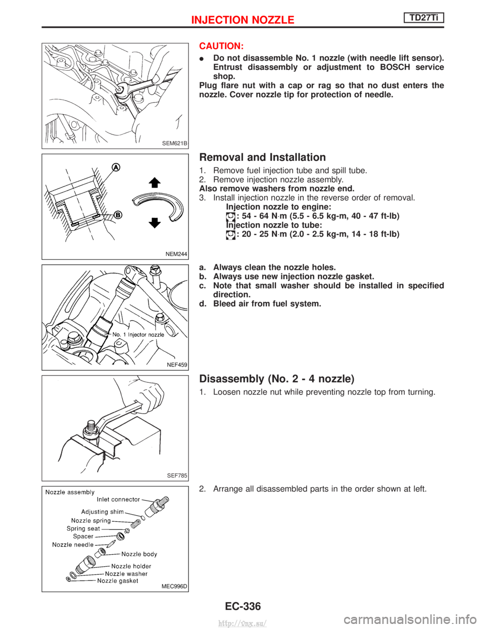
CAUTION:
IDo not disassemble No. 1 nozzle (with needle lift sensor).
Entrust disassembly or adjustment to BOSCH service
shop.
Plug flare nut with a cap or rag so that no dust enters the
nozzle. Cover nozzle tip for protection of needle.
Removal and Installation
1. Remove fuel injection tube and spill tube.
2. Remove injection nozzle assembly.
Also remove washers from nozzle end.
3. Install injection nozzle in the reverse order of removal. Injection nozzle to engine:
:54-64N ×m (5.5 - 6.5 kg-m, 40 - 47 ft-lb)
Injection nozzle to tube:
:20-25N ×m (2.0 - 2.5 kg-m, 14 - 18 ft-lb)
a. Always clean the nozzle holes.
b. Always use new injection nozzle gasket.
c. Note that small washer should be installed in specified direction.
d. Bleed air from fuel system.
Disassembly (No.2-4nozzle)
1. Loosen nozzle nut while preventing nozzle top from turning.
2. Arrange all disassembled parts in the order shown at left.
SEM621B
NEM244
NEF459
SEF785
MEC996D
INJECTION NOZZLETD27Ti
EC-336
http://vnx.su/