2004 NISSAN TERRANO Ignition
[x] Cancel search: IgnitionPage 5 of 1833

Observe the following precautions to ensure safe and proper
servicing. These precautions are not described in each indi-
vidual section.
1. Do not operate the engine for an extended period of time with-out proper exhaust ventilation.
Keep the work area well ventilated and free of any inflammable
materials. Special care should be taken when handling any
inflammable or poisonous materials, such as gasoline, refriger-
ant gas, etc. When working in a pit or other enclosed area, be
sure to properly ventilate the area before working with hazard-
ous materials.
Do not smoke while working on the vehicle.
2. Before jacking up the vehicle, apply wheel chocks or other tire blocks to the wheels to prevent the vehicle from moving. After
jacking up the vehicle, support the vehicle weight with safety
stands at the points designated for proper lifting and towing
before working on the vehicle.
These operations should be done on a level surface.
3. When removing a heavy component such as the engine or transaxle/transmission, take care not to lose your balance and
drop it. Also, do not allow it to strike adjacent parts, especially
the brake tubes and master cylinder.
4. Before starting repairs which do not require battery power, always turn off the ignition switch, then disconnect the ground
cable from the battery to prevent accidental short circuit.
5. To prevent serious burns, avoid contact with hot metal parts such as the radiator, exhaust manifold, tail pipe and muffler. Do
not remove the radiator cap when the engine is hot.
SGI285
SGI231
SGI232
SGI233
PRECAUTIONS
GI-2
http://vnx.su/
Page 7 of 1833

insulation (either just before the harness connectors or for
the complete harness), for easy identification.
Precautions for NATS
NATS (Nissan Anti-Theft System)
NATS will immobilize the engine if someone tries to start it without
the registered key of NATS.
Both of the originally supplied ignition key IDs have been NATS
registered.
The NATS security indicator is located on the instrument panel. The
indicator blinks when the ignition switch is in ªOFFº or ªACCº posi-
tion. Therefore, NATS warns outsiders that the vehicle is equipped
with the anti-theft system.
IWhen NATS detects trouble, the malfunction indicator lamp
(MIL) blinks.
This blinking indicates that the anti-theft is not functioning, so
prompt service is required.
I If the malfunction indicator lamp comes on while the engine is
running, return the vehicle to the workshop before turning the
ignition switch ªOFFº.
Once the ignition switch is turned ªOFFº, the engine can not be
started.
I When servicing NATS (trouble diagnoses, system initialization
and additional registration of other NATS ignition key IDs) CON-
SULT-II hardware and CONSULT-II NATS software is neces-
sary.
Regarding the procedures of NATS initialization and NATS igni-
tion key ID registration, refer to CONSULT-II operation manual,
NATS.
Therefore, CONSULT-II NATS software (program card and
operation manual) must be kept strictly confidential to main-
tain the integrity of the anti-theft function.
I When servicing NATS (trouble diagnoses, system initialization
and additional registration of other NATS ignition key IDs), it
may be necessary to re-register original key identification.
Therefore, be sure to receive all keys from vehicle owner.
A maximum of five key IDs can be registered into NATS.
I When failing to start the engine first-time using the key of
NATS, starts as follows:
(1) Turn ignition key to ªOFFº.
(2) Wait approx. 5 seconds.
(3) Turn ignition key to ªSTARTº again while keeping the key
apart from any others on key-chain.
SGI916
PRECAUTIONS
Supplemental Restraint System (SRS) ªAIR
BAGº and ªSEAT BELT PRE-TENSIONERº
(Dual Air Bag System) (Cont'd)
GI-4
http://vnx.su/
Page 8 of 1833

Precautions for Multiport Fuel Injection System
or Engine Control System
1. Before connecting or disconnecting any harness connector forthe multiport fuel injection system or ECM (Engine Control
Module):
Turn ignition switch to ªOFFº position.
Disconnect negative battery terminal.
Otherwise, there may be damage to ECM.
2. Before disconnecting pressurized fuel line from fuel pump to injectors, be sure to release fuel pressure to eliminate danger.
3. Be careful not to jar components such as control unit and air flow meter.
Precautions for Catalyst
If a large amount of unburned fuel enters the converter, the con-
verter temperature will rise to excessively high values. To prevent
this, follow the procedure below:
1. Use unleaded gasoline only. Leaded gasoline will seriouslydamage the catalytic converter.
2. When checking for ignition spark or measuring engine compression, perform tests quickly and only when necessary.
3. Do not run engine when the fuel tank level is low, as a result the engine may misfire causing damage to the converter.
4. Do not place the vehicle on inflammable material. Keep inflam- mable material off the exhaust pipe.
Precautions for Turbocharger
The turbocharger turbine revolves at extremely high speeds and
becomes very hot. Therefore, it is essential to maintain a clean
supply of oil flowing through the turbocharger and to follow all
required maintenance instructions and operating procedures.
For proper operation of the system, follow the procedure below:
1. Always use the recommended oil. Follow the instructions forproper time to change the oil and proper oil level.
2. Avoid accelerating engine to a high rpm immediately after start- ing.
3. If engine had been operating at high rpm for an extended period of time, let it idle for a few minutes prior to shutting it off.
SGI787
SGI290
SGI292
PRECAUTIONS
GI-5
http://vnx.su/
Page 18 of 1833

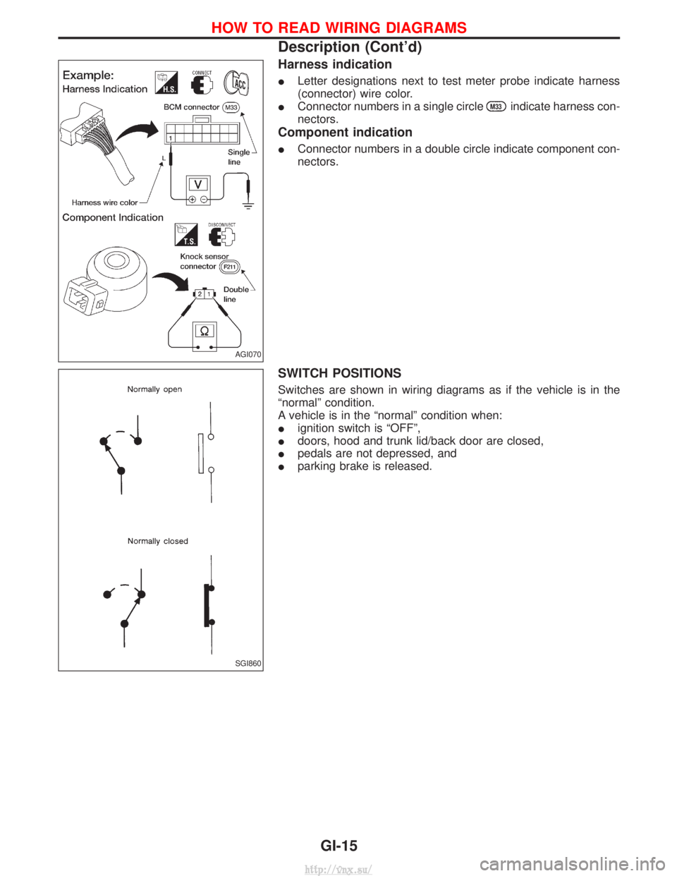
Harness indication
ILetter designations next to test meter probe indicate harness
(connector) wire color.
I Connector numbers in a single circle
M33indicate harness con-
nectors.
Component indication
I Connector numbers in a double circle indicate component con-
nectors.
SWITCH POSITIONS
Switches are shown in wiring diagrams as if the vehicle is in the
ªnormalº condition.
A vehicle is in the ªnormalº condition when:
Iignition switch is ªOFFº,
I doors, hood and trunk lid/back door are closed,
I pedals are not depressed, and
I parking brake is released.
AGI070
SGI860
HOW TO READ WIRING DIAGRAMS
Description (Cont'd)
GI-15
http://vnx.su/
Page 28 of 1833

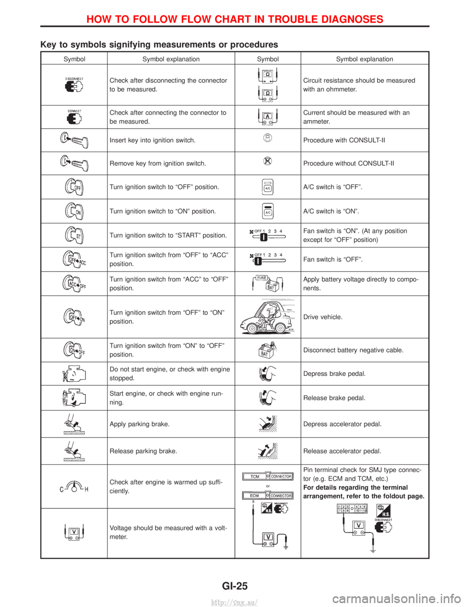
Key to symbols signifying measurements or procedures
SymbolSymbol explanation SymbolSymbol explanation
Check after disconnecting the connector
to be measured.Circuit resistance should be measured
with an ohmmeter.
Check after connecting the connector to
be measured.Current should be measured with an
ammeter.
Insert key into ignition switch.Procedure with CONSULT-II
Remove key from ignition switch.Procedure without CONSULT-II
Turn ignition switch to ªOFFº position.A/C switch is ªOFFº.
Turn ignition switch to ªONº position.A/C switch is ªONº.
Turn ignition switch to ªSTARTº position.Fan switch is ªONº. (At any position
except for ªOFFº position)
Turn ignition switch from ªOFFº to ªACCº
position.Fan switch is ªOFFº.
Turn ignition switch from ªACCº to ªOFFº
position.Apply battery voltage directly to compo-
nents.
Turn ignition switch from ªOFFº to ªONº
position.Drive vehicle.
Turn ignition switch from ªONº to ªOFFº
position.Disconnect battery negative cable.
Do not start engine, or check with engine
stopped.Depress brake pedal.
Start engine, or check with engine run-
ning.Release brake pedal.
Apply parking brake.Depress accelerator pedal.
Release parking brake.Release accelerator pedal.
Check after engine is warmed up suffi-
ciently.
Pin terminal check for SMJ type connec-
tor (e.g. ECM and TCM, etc.)
For details regarding the terminal
arrangement, refer to the foldout page.
Voltage should be measured with a volt-
meter.
HOW TO FOLLOW FLOW CHART IN TROUBLE DIAGNOSES
GI-25
http://vnx.su/
Page 29 of 1833

Function and System Application
Diagnostictest mode Function ENGINE A/T Air bag ABS NATS*1
Self-diagnostic results Self-diagnostic results can be read and erased quickly. xxxxx
ECU discriminated No. Classification number of a replacement ECU can be
read to prevent an incorrect ECU from being installed. ÐÐxÐÐ
Data monitor Input/Output data in the ECM can be read. x xÐxÐ
Active test Diagnostic Test Mode in which CONSULT-II drives
some actuators apart from the ECMs and also shifts
some parameters in a specified range. xÐÐxÐ
ECU (ECM) part number ECU (ECM) part number can be read. x xÐxÐ
Control unit initialisation All registered ignition key IDs in NATS components can
be initialised and new IDs can be registered. ÐÐÐÐ x
Self-function check ECM checks its own NATS communication interface. ÐÐÐÐ x
x: Applicable
*1: NATS: Nissan Anti-Theft System
Nickel Metal Hydride Battery Replacement
CONSULT-II contains a nickel metal hydride battery. When replacing the battery obey the following:
WARNING:
Replace the nickel metal hydride battery with genuine CONSULT-II battery only. Use of another battery
may present a risk of fire or explosion. The battery may present a fire or chemical burn hazard if mis-
treated. Do not recharge, disassemble of dispose of in fire.
Keep the battery out of reach of children and discard used battery conforming to the local regulations.
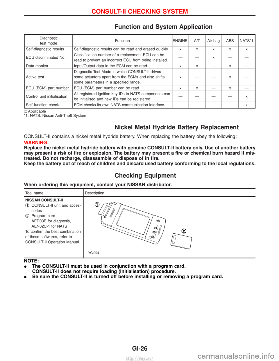
Checking Equipment
When ordering this equipment, contact your NISSAN distributor.
Tool name Description
NISSAN CONSULT-II
q
1CONSULT-II unit and acces-
sories
q
2Program card
AED03E for diagnosis,
AEN02C-1 for NATS
To confirm the best combination
of these softwares, refer to
CONSULT-II Operation Manual.
YGI004
NOTE:
I The CONSULT-II must be used in conjunction with a program card.
CONSULT-II does not require loading (Initialisation) procedure.
I Be sure the CONSULT-II is turned off before installing or removing a program card.
CONSULT-II CHECKING SYSTEM
GI-26
http://vnx.su/
Page 35 of 1833

4-pole Lift
WARNING:
Do not use a 2-pole lift.
Due to weight balance of the vehicle and shape of underbody,
lift arms can not be attached in a safe way. Therefore it is rec-
ommended to use a 4-pole lift only.
Tow Truck Towing
CAUTION:
IAll applicable local laws regarding the towing operation
must be obeyed.
I It is necessary to use proper towing equipment to avoid
possible damage to the vehicle during a towing operation.
I Attach safety chains for all towing.
I When towing, make sure that the transmission, steering
system and power train are in good order. If any unit is
damaged, a dolly must be used.
I When towing with the front wheels on the ground:
Move both the gearshift and transfer levers to neutral (ªNº
position).
Turn the ignition key to the ªOFFº position and secure the
steering wheel in a straightahead position with a rope or
similar device. Never place the ignition key in the ªLOCKº
position. This will result in damage to the steering lock
mechanism.
I When towing with the rear wheels on the ground, release
the parking brake and move both the gearshift and trans-
fer levers to neutral (ªNº position).
I Never tow vehicle from the rear (i.e., backward) with four
wheels on the ground as this may cause serious and
expensive damage to the transmission.
LIFTING POINTS AND TOW TRUCK TOWING
GI-32
http://vnx.su/
Page 37 of 1833

ISO 15031-2 Terminology List
All emission related terms used in this publication in accordance with ISO 15031-2 are listed. Accordingly, new
terms, new acronyms/abbreviations and old terms are listed in the following chart.
***: Not applicable
NEW TERMNEW ACRONYM/
ABBREVIATION OLD TERM
Air cleaner ACL Air cleaner
Barometric pressure BARO
Barometric pressure sensor-BCDD BAROS-BCDD BCDD
Camshaft position CMP ***
Camshaft position sensor CMPS Crank angle sensor
Carburetor CARB Carburetor
Charge air cooler CAC Intercooler
Closed loop CL Closed loop
Closed throttle position switch CTP switch Idle switch
Clutch pedal position switch CPP switch Clutch switch
Continuous fuel injection system CFI system ***
Continuous trap oxidizer system CTOX system ***
Crankshaft position CKP ***
Crankshaft position sensor CKPS ***
Data link connector DLC ***
Data link connector for CONSULT DLC for CONSULT Diagnostic connector for CONSULT
Diagnostic test mode DTM Diagnostic mode
Diagnostic test mode selector DTM selector Diagnostic mode selector
Diagnostic test mode I DTM I Mode I
Diagnostic test mode II DTM II Mode II
Diagnostic trouble code DTC Malfunction code
Direct fuel injection system DFI system ***
Distributor ignition system DI system Ignition timing control
Early fuel evaporation-mixture heater EFE-mixture heater Mixture heater
Early fuel evaporation system EFE system Mixture heater control
Electrically erasable programmable read only
memory EEPROM ***
Electronic ignition system EI system Ignition timing control
Engine control module ECM ECCS control unit
Engine coolant temperature ECT Engine temperature
Engine coolant temperature sensor ECTS Engine temperature sensor
Engine modification EM ***
Engine speed RPM Engine speed
Erasable programmable read only memory EPROM ***
Evaporative emission system EVAP system Evaporative emission control system
Exhaust gas recirculation valve EGR valve EGR valve
Exhaust gas recirculation control-BPT valve EGRC-BPT valve BPT valve
Exhaust gas recirculation control-solenoid valve EGRC-solenoid valve EGR control solenoid valve
ISO 15031-2 TERMINOLOGY LIST
GI-34
http://vnx.su/