2004 NISSAN TERRANO catalytic converter
[x] Cancel search: catalytic converterPage 8 of 1833

Precautions for Multiport Fuel Injection System
or Engine Control System
1. Before connecting or disconnecting any harness connector forthe multiport fuel injection system or ECM (Engine Control
Module):
Turn ignition switch to ªOFFº position.
Disconnect negative battery terminal.
Otherwise, there may be damage to ECM.
2. Before disconnecting pressurized fuel line from fuel pump to injectors, be sure to release fuel pressure to eliminate danger.
3. Be careful not to jar components such as control unit and air flow meter.
Precautions for Catalyst
If a large amount of unburned fuel enters the converter, the con-
verter temperature will rise to excessively high values. To prevent
this, follow the procedure below:
1. Use unleaded gasoline only. Leaded gasoline will seriouslydamage the catalytic converter.
2. When checking for ignition spark or measuring engine compression, perform tests quickly and only when necessary.
3. Do not run engine when the fuel tank level is low, as a result the engine may misfire causing damage to the converter.
4. Do not place the vehicle on inflammable material. Keep inflam- mable material off the exhaust pipe.
Precautions for Turbocharger
The turbocharger turbine revolves at extremely high speeds and
becomes very hot. Therefore, it is essential to maintain a clean
supply of oil flowing through the turbocharger and to follow all
required maintenance instructions and operating procedures.
For proper operation of the system, follow the procedure below:
1. Always use the recommended oil. Follow the instructions forproper time to change the oil and proper oil level.
2. Avoid accelerating engine to a high rpm immediately after start- ing.
3. If engine had been operating at high rpm for an extended period of time, let it idle for a few minutes prior to shutting it off.
SGI787
SGI290
SGI292
PRECAUTIONS
GI-5
http://vnx.su/
Page 38 of 1833

***: Not applicable
NEW TERMNEW ACRONYM/
ABBREVIATION OLD TERM
Exhaust gas recirculation temperature sensor EGR temperature sensor Exhaust gas temperature sensor
Flash electrically erasable programmable read
only memory FEEPROM ***
Flash erasable programmable read only memory FEPROM ***
Flexible fuel sensor FFS ***
Flexible fuel system FF system ***
Heated Oxygen sensor HO
2S Exhaust gas sensor
Idle air control system IAC systemIdle speed control
Idle air control valve-air regulator IACV-air regulatorAir regulator
Idle air control valve-auxiliary air control valve IACV-AAC valve Auxiliary air control (AAC) valve
Idle air control valve-FICD solenoid valve IACV-FICD solenoid valve FICD solenoid valve
Idle air control valve-idle up control solenoid
valve IACV-idle up control solenoid
valve
Idle up control solenoid valve
Idle speed control-FI pot ISC-FI potFI pot
Idle speed control system ISC system***
Ignition control module ICM***
Indirect fuel injection system IFI system***
Intake air temperature sensor IATS Air temperature sensor
Knock *** Detonation
Knock sensor KS Detonation sensor
Malfunction indicator MI Check engine light
Manifold absolute pressure MAP ***
Manifold absolute pressure sensor MAPS ***
Manifold differential pressure MDP ***
Manifold differential pressure sensor MDPS ***
Manifold surface temperature MST ***
Manifold surface temperature sensor MSTS ***
Manifold vacuum zone MVZ ***
Manifold vacuum zone sensor MVZS ***
Mass air flow sensor MAFS Air flow meter
Mixture control solenoid valve MC solenoid valve Air-fuel control solenoid valve
Multiport fuel injection system MFI system Fuel injection control
Neutral position switch *** Neutral switch
Non-volatile random access memory NVRAM ***
On-board diagnostic system OBD system Self-diagnosis
Open loop OL Open loop
Oxidation catalyst OC Catalyst
Oxidation catalytic converter system OC system ***
Oxygen sensor O
2S Exhaust gas sensor
Park position switch ***Park switch
Park/neutral position switch PNP switch Park/neutral switch
Periodic trap oxidizer system PTOX system ***
ISO 15031-2 TERMINOLOGY LIST
ISO 15031-2 Terminology List (Cont'd)
GI-35
http://vnx.su/
Page 39 of 1833

***: Not applicable
NEW TERMNEW ACRONYM/
ABBREVIATION OLD TERM
Powertrain control module PCM ***
Programmable read only memory PROM ***
Pulsed secondary air injection control solenoid
valve PAIRC solenoid valve AIV control solenoid valve
Pulsed secondary air injection system PAIR system Air induction valve (AIV) control
Pulsed secondary air injection valve PAIR valve Air induction valve
Random access memory RAM ***
Read only memory ROM ***
Scan tool ST ***
Secondary air injection pump AIR pump ***
Secondary air injection system AIR system ***
Sequential multiport fuel injection system SFI system Sequential fuel injection
Service reminder indicator SRI ***
Simultaneous multiport fuel injection system *** Simultaneous fuel injection
Smoke puff limiter system SPL system ***
Supercharger SC ***
Supercharger bypass SCB ***
System readiness test SRT ***
Thermal vacuum valve TVV Thermal vacuum valve
Three way catalyst TWC Catalyst
Three way catalytic converter system TWC system ***
Three way + oxidation catalyst TWC + OC Catalyst
Three way + oxidation catalytic converter system TWC + OC system ***
Throttle body TB Throttle chamber
SPI body
Throttle body fuel injection system TBI system Fuel injection control
Throttle position TP Throttle position
Throttle position sensor TPS Throttle sensor
Throttle position switch TP switch Throttle switch
Torque converter clutch solenoid valve TCC solenoid valve Lock-up cancel solenoid
lock-up solenoid
Turbocharger TC Turbocharger
Vehicle speed sensor VSS Vehicle speed sensor
Volume air flow sensor VAFS Air flow meter
Warm up oxidation catalyst WU-OC Catalyst
Warm up oxidation catalytic converter system WU-OC system ***
Warm up three-way catalyst WU-TWC Catalyst
Warm up three-way catalytic converter system WU-TWC system ***
Wide open throttle position switch WOP switch Full switch
ISO 15031-2 TERMINOLOGY LIST
ISO 15031-2 Terminology List (Cont'd)
GI-36
http://vnx.su/
Page 106 of 1833

2. Remove catalyst.
CAUTION:
Do not disassemble catalyst.
Inspection
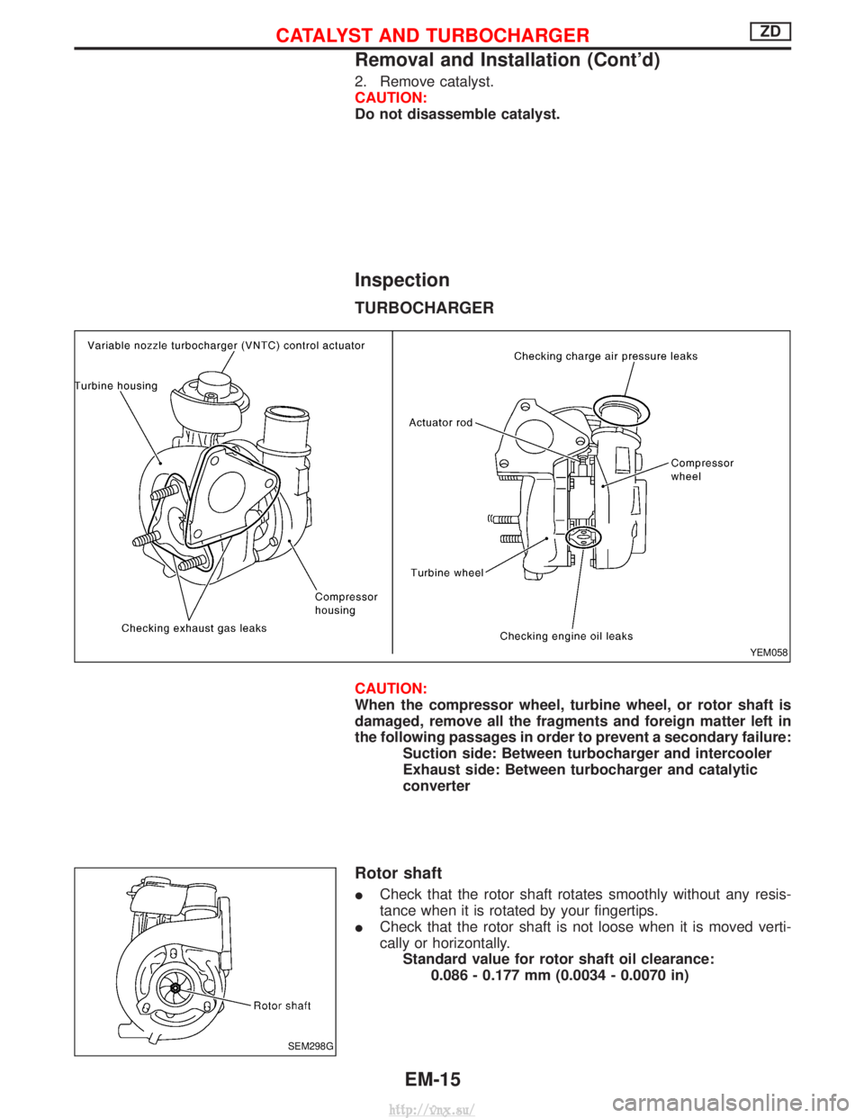
TURBOCHARGER
CAUTION:
When the compressor wheel, turbine wheel, or rotor shaft is
damaged, remove all the fragments and foreign matter left in
the following passages in order to prevent a secondary failure:Suction side: Between turbocharger and intercooler
Exhaust side: Between turbocharger and catalytic
converter
Rotor shaft
ICheck that the rotor shaft rotates smoothly without any resis-
tance when it is rotated by your fingertips.
I Check that the rotor shaft is not loose when it is moved verti-
cally or horizontally.
Standard value for rotor shaft oil clearance: 0.086 - 0.177 mm (0.0034 - 0.0070 in)
YEM058
SEM298G
CATALYST AND TURBOCHARGERZD
Removal and Installation (Cont'd)
EM-15
http://vnx.su/
Page 109 of 1833

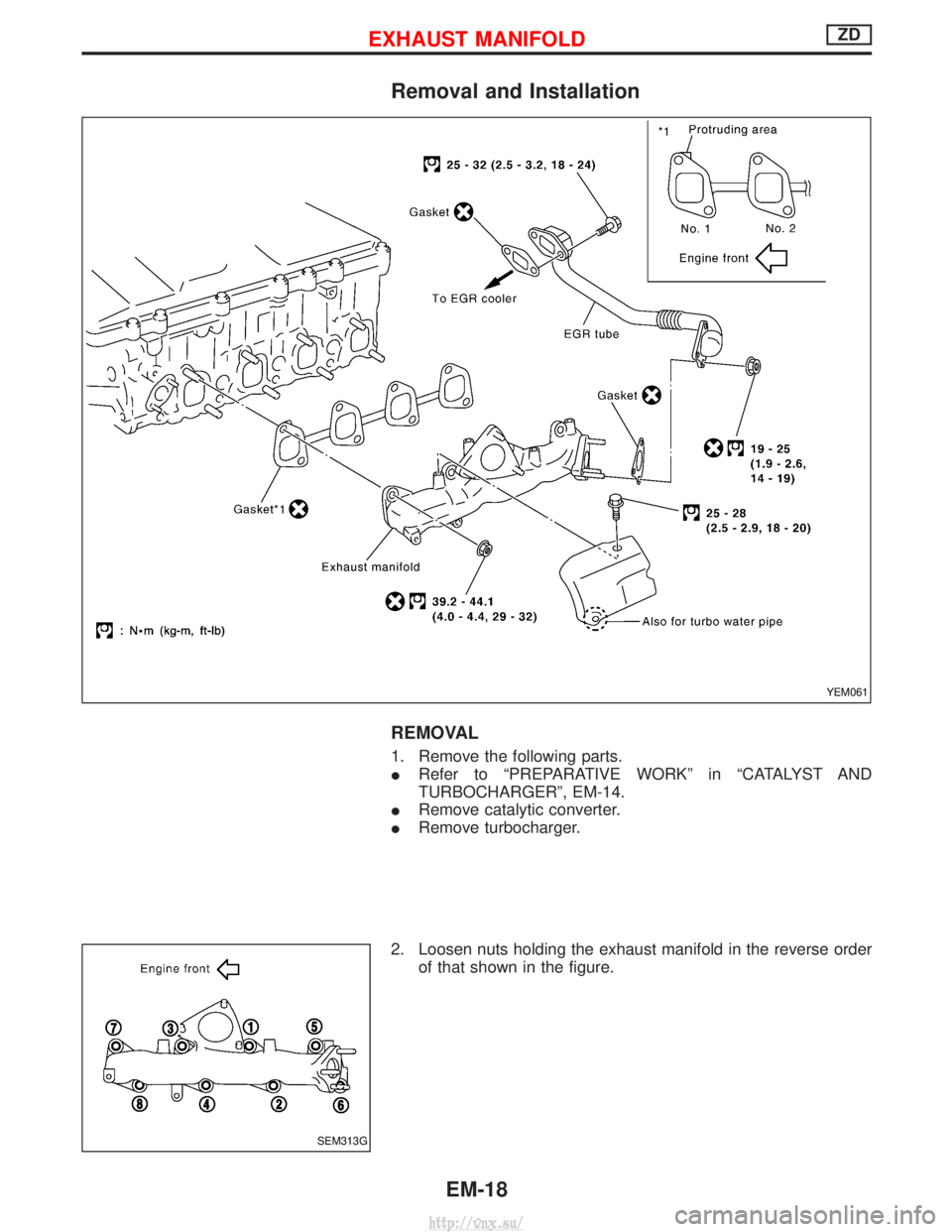
Removal and Installation
REMOVAL
1. Remove the following parts.
IRefer to ªPREPARATIVE WORKº in ªCATALYST AND
TURBOCHARGERº, EM-14.
I Remove catalytic converter.
I Remove turbocharger.
2. Loosen nuts holding the exhaust manifold in the reverse order of that shown in the figure.
YEM061
SEM313G
EXHAUST MANIFOLDZD
EM-18
http://vnx.su/
Page 143 of 1833

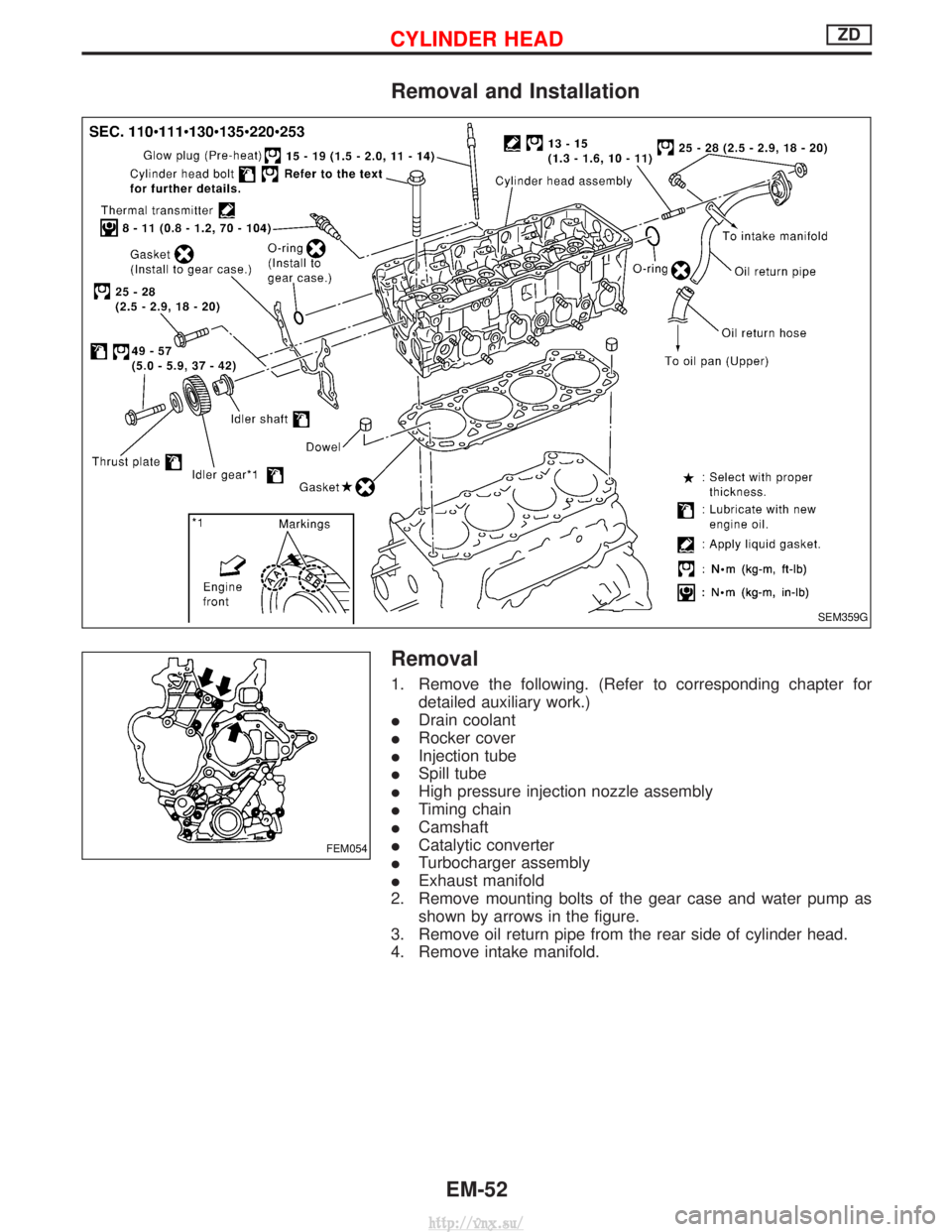
Removal and Installation
Removal
1. Remove the following. (Refer to corresponding chapter fordetailed auxiliary work.)
I Drain coolant
I Rocker cover
I Injection tube
I Spill tube
I High pressure injection nozzle assembly
I Timing chain
I Camshaft
I Catalytic converter
I Turbocharger assembly
I Exhaust manifold
2. Remove mounting bolts of the gear case and water pump as shown by arrows in the figure.
3. Remove oil return pipe from the rear side of cylinder head.
4. Remove intake manifold.
SEM359G
FEM054
CYLINDER HEADZD
EM-52
http://vnx.su/
Page 155 of 1833

Engine room (Left)
3. Remove air duct and air cleaner case.
4. Disconnect vacuum hose to the vehicle on the engine.
5. Disconnect harness connectors from alternator and air com-pressor.
6. Remove alternator.
7. After removing refrigerant, remove pipes of air compressor and inlet/outlet.
8. Disconnect heating hose, install blank cap to hose to prevent coolant from leaking.
9. Remove heating pipe.
10. Remove heat insulator.
11. Remove catalytic converter.
Engine room (Right)
12. Remove power steering reservoir tank from bracket, and fix it to the vehicle with a rope.
CAUTION:
Keep the reservoir tank level when fixing to prevent oil leak.
13. Remove fuel feed and return hoses.
CAUTION:
Install blank caps immediately to avoid fuel leakage.
14. Remove all harness connectors on the engine, and move har- nesses to the side of the vehicle.
Vehicle underfloor
15. Remove starter motor.
16. Detach A/T oil cooler pipes from oil pan. (A/T model)
17. Remove rear propeller shaft.
18. Remove mounting bolts to secure the engine to transmission.
1) Remove torque converter installation bolt. (A/T model)
2) Lift transmission bottom with transmission jack, and removerear mount members from the vehicle.
3) Lower transmission with the jack, and remove upper mounting bolts securing the engine to transmission.
4) Lift transmission with the jack, and reinstall rear mount mem- bers to the vehicle.
5) Position the jack to the front side of transmission.
6) Remove remaining mounting bolts securing the engine to trans- mission.
Removal operation
19. Remove air conditioner high pressure pipes at the rear of theengine room.
I This is due to some inconvenience in the rear slinger installa-
tion.
20. Install the engine slingers (standard service part) to front-left and rear-right.
:25-28N ×m (2.5 - 2.9 kg-m, 18 - 20 ft-lb)
WARNING:
For engines without engine slingers, attach proper slingers
and bolts described in the PARTS CATALOG.
FEM082
ENGINE REMOVALZD
Removal (Cont'd)
EM-64
http://vnx.su/
Page 159 of 1833

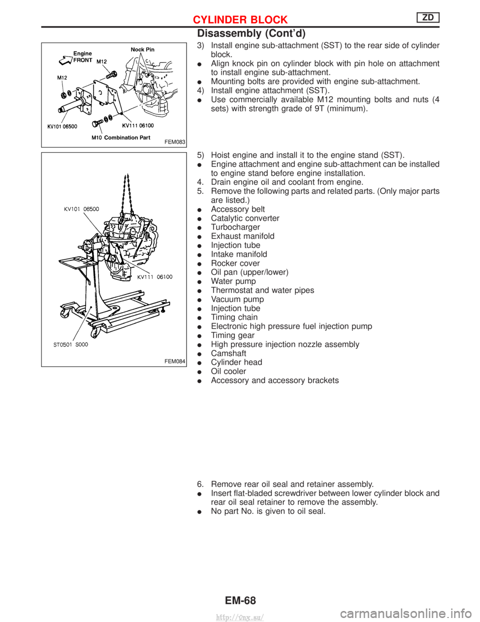
3) Install engine sub-attachment (SST) to the rear side of cylinderblock.
I Align knock pin on cylinder block with pin hole on attachment
to install engine sub-attachment.
I Mounting bolts are provided with engine sub-attachment.
4) Install engine attachment (SST).
I Use commercially available M12 mounting bolts and nuts (4
sets) with strength grade of 9T (minimum).
5) Hoist engine and install it to the engine stand (SST).
I Engine attachment and engine sub-attachment can be installed
to engine stand before engine installation.
4. Drain engine oil and coolant from engine.
5. Remove the following parts and related parts. (Only major parts are listed.)
I Accessory belt
I Catalytic converter
I Turbocharger
I Exhaust manifold
I Injection tube
I Intake manifold
I Rocker cover
I Oil pan (upper/lower)
I Water pump
I Thermostat and water pipes
I Vacuum pump
I Injection tube
I Timing chain
I Electronic high pressure fuel injection pump
I Timing gear
I High pressure injection nozzle assembly
I Camshaft
I Cylinder head
I Oil cooler
I Accessory and accessory brackets
6. Remove rear oil seal and retainer assembly.
I Insert flat-bladed screwdriver between lower cylinder block and
rear oil seal retainer to remove the assembly.
I No part No. is given to oil seal.
FEM083
FEM084
CYLINDER BLOCKZD
Disassembly (Cont'd)
EM-68
http://vnx.su/