2004 NISSAN TERRANO turn signal
[x] Cancel search: turn signalPage 1515 of 1833
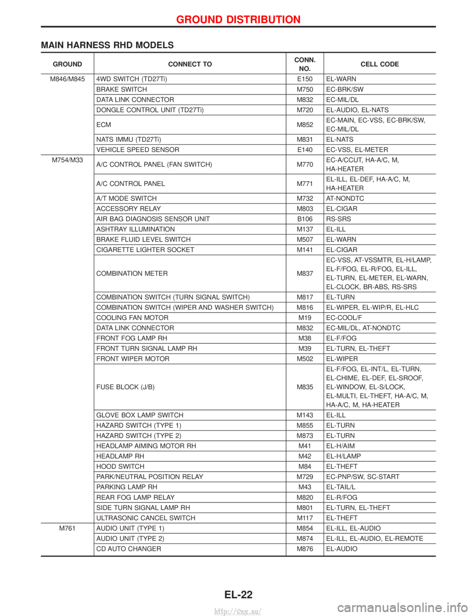
MAIN HARNESS RHD MODELS
GROUNDCONNECT TO CONN.
NO. CELL CODE
M846/M845 4WD SWITCH (TD27Ti) E150 EL-WARN
BRAKE SWITCH M750 EC-BRK/SW
DATA LINK CONNECTOR M832 EC-MIL/DL
DONGLE CONTROL UNIT (TD27Ti) M720 EL-AUDIO, EL-NATS
ECM M852EC-MAIN, EC-VSS, EC-BRK/SW,
EC-MIL/DL
NATS IMMU (TD27Ti) M831 EL-NATS
VEHICLE SPEED SENSOR E140 EC-VSS, EL-METER
M754/M33 A/C CONTROL PANEL (FAN SWITCH) M770EC-A/CCUT, HA-A/C, M,
HA-HEATER
A/C CONTROL PANEL M771EL-ILL, EL-DEF, HA-A/C, M,
HA-HEATER
A/T MODE SWITCH M732 AT-NONDTC
ACCESSORY RELAY M803 EL-CIGAR
AIR BAG DIAGNOSIS SENSOR UNIT B106 RS-SRS
ASHTRAY ILLUMINATION M137 EL-ILL
BRAKE FLUID LEVEL SWITCH M507 EL-WARN
CIGARETTE LIGHTER SOCKET M141 EL-CIGAR
COMBINATION METER M837EC-VSS, AT-VSSMTR, EL-H/LAMP,
EL-F/FOG, EL-R/FOG, EL-ILL,
EL-TURN, EL-METER, EL-WARN,
EL-CLOCK, BR-ABS, RS-SRS
COMBINATION SWITCH (TURN SIGNAL SWITCH) M817 EL-TURN
COMBINATION SWITCH (WIPER AND WASHER SWITCH) M816 EL-WIPER, EL-WIP/R, EL-HLC
COOLING FAN MOTOR M19 EC-COOL/F
DATA LINK CONNECTOR M832 EC-MIL/DL, AT-NONDTC
FRONT FOG LAMP RH M38 EL-F/FOG
FRONT TURN SIGNAL LAMP RH M39 EL-TURN, EL-THEFT
FRONT WIPER MOTOR M502 EL-WIPER
FUSE BLOCK (J/B) M835 EL-F/FOG, EL-INT/L, EL-TURN,
EL-CHIME, EL-DEF, EL-SROOF,
EL-WINDOW, EL-S/LOCK,
EL-MULTI, EL-THEFT, HA-A/C, M,
HA-A/C, M, HA-HEATER
GLOVE BOX LAMP SWITCH M143 EL-ILL
HAZARD SWITCH (TYPE 1) M855 EL-TURN
HAZARD SWITCH (TYPE 2) M873 EL-TURN
HEADLAMP AIMING MOTOR RH M41 EL-H/AIM
HEADLAMP RH M42 EL-H/LAMP
HOOD SWITCH M84 EL-THEFT
PARK/NEUTRAL POSITION RELAY M729 EC-PNP/SW, SC-START
PARKING LAMP RH M43 EL-TAIL/L
REAR FOG LAMP RELAY M820 EL-R/FOG
SIDE TURN SIGNAL LAMP RH M801 EL-TURN, EL-THEFT
ULTRASONIC CANCEL SWITCH M117 EL-THEFT
M761 AUDIO UNIT (TYPE 1) M854 EL-ILL, EL-AUDIO AUDIO UNIT (TYPE 2) M874 EL-ILL, EL-AUDIO, EL-REMOTE
CD AUTO CHANGER M876 EL-AUDIO
GROUND DISTRIBUTION
EL-22
http://vnx.su/
Page 1552 of 1833
![NISSAN TERRANO 2004 Service Repair Manual System Description
TURN SIGNAL OPERATION
Power is supplied at all times
Ithrough 10A fuse [No. 5, located in fuse block (J/B)]
I to time control unit terminal U09, and
With the ignition switch in the NISSAN TERRANO 2004 Service Repair Manual System Description
TURN SIGNAL OPERATION
Power is supplied at all times
Ithrough 10A fuse [No. 5, located in fuse block (J/B)]
I to time control unit terminal U09, and
With the ignition switch in the](/manual-img/5/57394/w960_57394-1551.png)
System Description
TURN SIGNAL OPERATION
Power is supplied at all times
Ithrough 10A fuse [No. 5, located in fuse block (J/B)]
I to time control unit terminal U09, and
With the ignition switch in the ON or START position, power is supplied
I through 10A fuse [No. 26, located in fuse block (J/B)]
I to time control unit terminal U01
Ground is supplied to time control unit terminal U16
I through fuse block (J/B) terminal MM2
I through body grounds F36 and F47 (LHD models) or
I through body grounds M33 and M754 (RHD models).
LH Turn
When the turn signal switch is turned to the L position, ground is supplied from body grounds M33 and M754
Ito time control unit terminal U02
I through fuse block (J/B) terminal E03
I through turn signal switch terminals 3 and 1
With ground is supplied, time control unit controls the flashing of the LH turn signal lamps.
Power is supplied from time control unit terminal U15
I to front turn signal lamp LH terminal 2,
I to side turn signal lamp LH terminal 2 and
I to rear combination lamp LH terminal 1
Ground is supplied to the front turn signal lamp LH terminal 1 through body grounds F36 and F47.
Ground is supplied to the side turn signal lamp LH terminal 1 through body grounds F36 and F47.
Ground is supplied to the rear combination lamp LH terminal 4 through body grounds B10 and B18.
RH Turn
When the turn signal switch is turned to the R position, ground is supplied from body grounds M33 and M754
I to time control unit terminal U04
I through fuse block (J/B) terminal E18
I through turn signal switch terminals 2 and 1
With ground is supplied, time control unit controls the flashing of the RH turn signal lamps.
Power is supplied from time control unit terminal U11
I to front turn signal lamp RH terminal 2,
I to side turn signal lamp RH terminal 2 and
I to rear combination lamp RH terminal 1
Ground is supplied to the front turn signal lamp RH terminal 1 through body grounds M33 and M754.
Ground is supplied to the side turn signal lamp RH terminal 1 through body grounds M33 and M754.
Ground is supplied to the rear combination lamp RH terminal 4 through body grounds B10 and B18.
HAZARD LAMP OPERATION
With the hazard switch in the ON position, ground is supplied from body grounds F36, F47 (LHD models) or
M33, M754 (RHD models)
I to time control unit terminal U05
I through fuse block (J/B) terminal M46
I through hazard switch terminals 17 and 19
With ground is supplied, time control unit controls the flashing of the hazard warning lamps.
Power is supplied from time control unit terminal U15
I to front turn signal lamp LH terminal 2,
I to side turn signal lamp LH terminal 2 and
I to rear combination lamp LH terminal 1
Power is supplied from time control unit terminal U11
I to front turn signal lamp RH terminal 2,
I to side turn signal lamp RH terminal 2 and
I to rear combination lamp RH terminal 1
Ground is supplied to terminal 1 of each front turn signal lamp through body grounds F36, F47 (LHD models)
or M33, M754 (RHD models).
Ground is supplied to terminal 1 of each side turn signal lamp through body grounds F36, F47 (LHD models)
EXTERIOR LAMP
EL-59
http://vnx.su/
Page 1559 of 1833
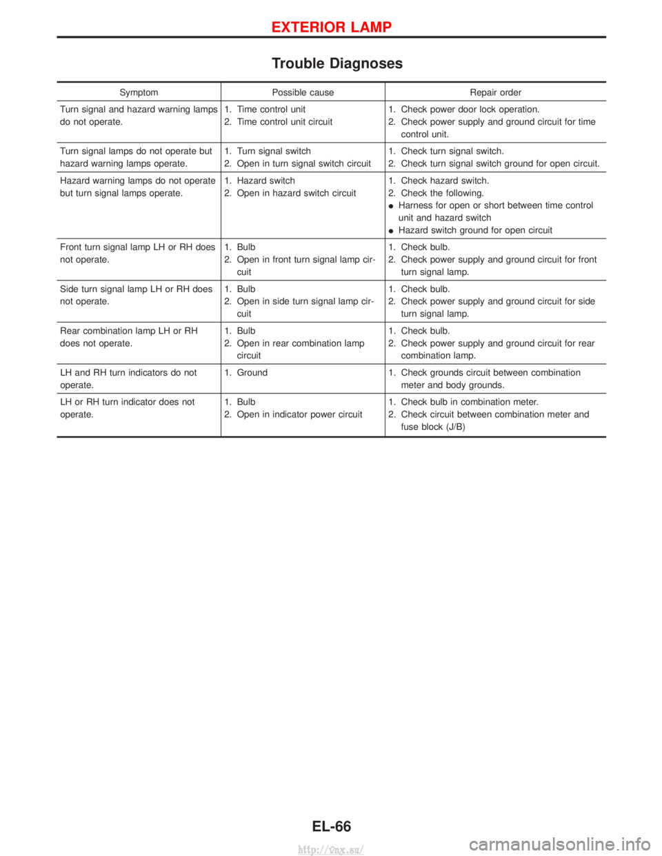
Trouble Diagnoses
SymptomPossible cause Repair order
Turn signal and hazard warning lamps
do not operate. 1. Time control unit
2. Time control unit circuit1. Check power door lock operation.
2. Check power supply and ground circuit for time
control unit.
Turn signal lamps do not operate but
hazard warning lamps operate. 1. Turn signal switch
2. Open in turn signal switch circuit1. Check turn signal switch.
2. Check turn signal switch ground for open circuit.
Hazard warning lamps do not operate
but turn signal lamps operate. 1. Hazard switch
2. Open in hazard switch circuit1. Check hazard switch.
2. Check the following.
I
Harness for open or short between time control
unit and hazard switch
I Hazard switch ground for open circuit
Front turn signal lamp LH or RH does
not operate. 1. Bulb
2. Open in front turn signal lamp cir-
cuit 1. Check bulb.
2. Check power supply and ground circuit for front
turn signal lamp.
Side turn signal lamp LH or RH does
not operate. 1. Bulb
2. Open in side turn signal lamp cir-
cuit 1. Check bulb.
2. Check power supply and ground circuit for side
turn signal lamp.
Rear combination lamp LH or RH
does not operate. 1. Bulb
2. Open in rear combination lamp
circuit 1. Check bulb.
2. Check power supply and ground circuit for rear
combination lamp.
LH and RH turn indicators do not
operate. 1. Ground
1. Check grounds circuit between combination
meter and body grounds.
LH or RH turn indicator does not
operate. 1. Bulb
2. Open in indicator power circuit1. Check bulb in combination meter.
2. Check circuit between combination meter and
fuse block (J/B)
EXTERIOR LAMP
EL-66
http://vnx.su/
Page 1566 of 1833
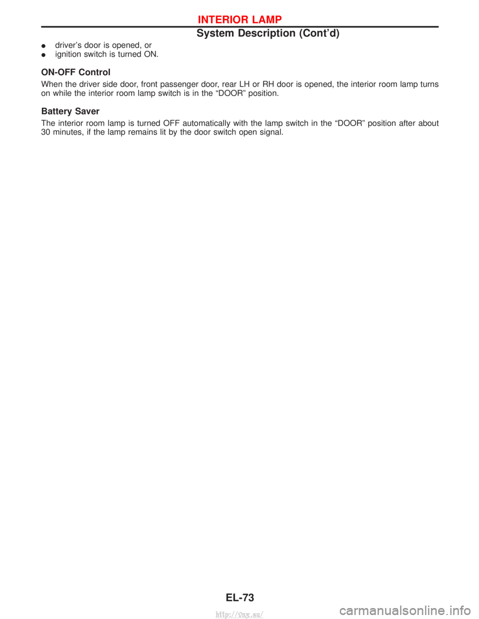
Idriver's door is opened, or
I ignition switch is turned ON.
ON-OFF Control
When the driver side door, front passenger door, rear LH or RH door is opened, the interior room lamp turns
on while the interior room lamp switch is in the ªDOORº position.
Battery Saver
The interior room lamp is turned OFF automatically with the lamp switch in the ªDOORº position after about
30 minutes, if the lamp remains lit by the door switch open signal.
INTERIOR LAMP
System Description (Cont'd)
EL-73
http://vnx.su/
Page 1591 of 1833
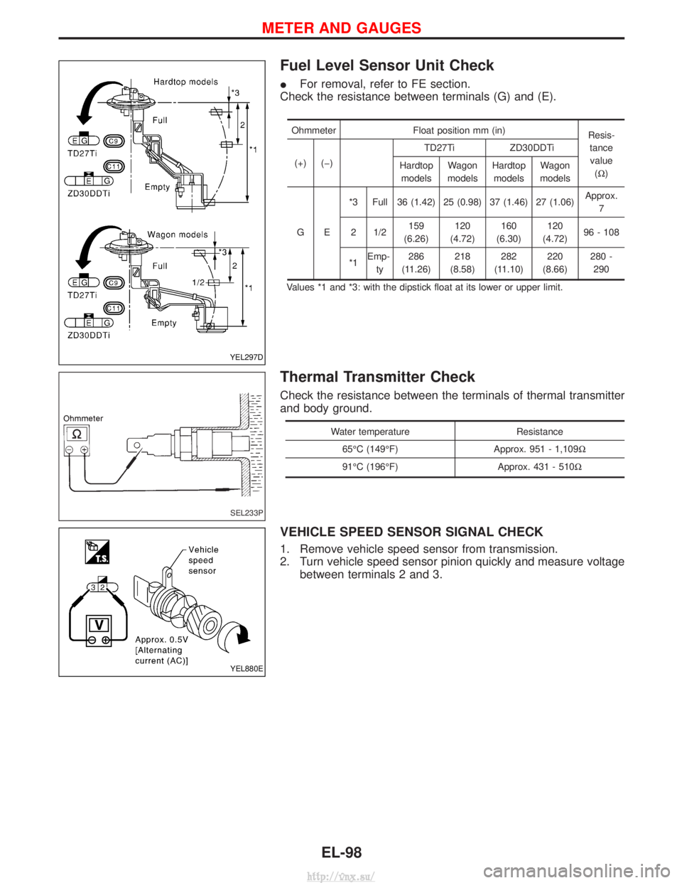
Fuel Level Sensor Unit Check
IFor removal, refer to FE section.
Check the resistance between terminals (G) and (E).
Ohmmeter Float position mm (in)
Resis-
tancevalue (W )
(+) (þ) TD27Ti ZD30DDTi
Hardtop models Wagon
models Hardtop
models Wagon
models
GE *3 Full 36 (1.42) 25 (0.98) 37 (1.46) 27 (1.06)
Approx.
7
2 1/2 159
(6.26) 120
(4.72) 160
(6.30) 120
(4.72) 96 - 108
*1 Emp-
ty 286
(11.26) 218
(8.58) 282
(11.10) 220
(8.66) 280 -
290
Values *1 and *3: with the dipstick float at its lower or upper limit.
Thermal Transmitter Check
Check the resistance between the terminals of thermal transmitter
and body ground.
Water temperature Resistance
65ÉC (149ÉF) Approx. 951 - 1,109W
91ÉC (196ÉF) Approx. 431 - 510W
VEHICLE SPEED SENSOR SIGNAL CHECK
1. Remove vehicle speed sensor from transmission.
2. Turn vehicle speed sensor pinion quickly and measure voltage between terminals 2 and 3.
YEL297D
SEL233P
YEL880E
METER AND GAUGES
EL-98
http://vnx.su/
Page 1656 of 1833
System Description
OPERATION
Power door lock/unlock operation by door key cylinder
IWith the key inserted into front door key cylinder, turning it to LOCK will lock all doors.
I With the key inserted into front door key cylinder, turning it to UNLOCK will unlock all doors.
Power door lock/unlock operation by multi-remote controller
I Pressing multi-remote controller LOCK button will lock all doors.
I Pressing multi-remote controller UNLOCK button once will unlock driver door. Then, if an unlock signal is
sent from the remote controller again within 5 seconds, all other doors will be unlocked.
Power door lock/unlock operation by lock/unlock switch
I With lock/unlock switch on driver door trim setting to LOCK will lock all doors.
I With lock/unlock switch on driver door trim setting to UNLOCK will unlock all doors.
Key reminder system
I If the ignition key is in the ignition key cylinder and driver door is open, setting lock/unlock switch, lock
knob, key or multi-remote controller to ªLOCKº locks the door once but then immediately unlocks all doors.
(signal from door unlock sensor driver side)
POWER DOOR LOCK
EL-163
http://vnx.su/
Page 1673 of 1833
System Description
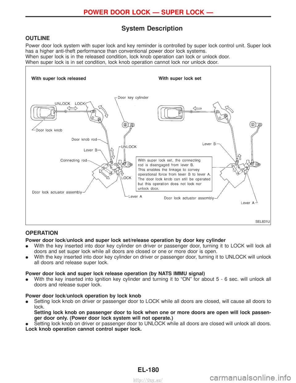
OUTLINE
Power door lock system with super lock and key reminder is controlled by super lock control unit. Super lock
has a higher anti-theft performance than conventional power door lock systems.
When super lock is in the released condition, lock knob operation can lock or unlock door.
When super lock is in set condition, lock knob operation cannot lock nor unlock door.
OPERATION
Power door lock/unlock and super lock set/release operation by door key cylinder
IWith the key inserted into door key cylinder on driver or passenger door, turning it to LOCK will lock all
doors and set super lock while all doors are closed or one or more door is open.
I With the key inserted into door key cylinder on driver or passenger door, turning it to UNLOCK will unlock
all doors and release super lock.
Power door lock and super lock release operation (by NATS IMMU signal)
I With the key inserted into ignition key cylinder and turning it to ªONº for abou t5-6sec. will unlock all
doors and release super lock.
Power door lock/unlock operation by lock knob
I Setting lock knob on driver or passenger door to LOCK while all doors are closed, will cause all doors to
lock.
Setting lock knob on passenger door to lock when one or more doors are open will lock passen-
ger door only. (Power door lock system will not operate.)
I Setting lock knob on driver or passenger door to UNLOCK while all doors are closed will unlock all doors.
Lock knob operation cannot control super lock.
SEL831U
POWER DOOR LOCK Ð SUPER LOCK Ð
EL-180
http://vnx.su/
Page 1693 of 1833
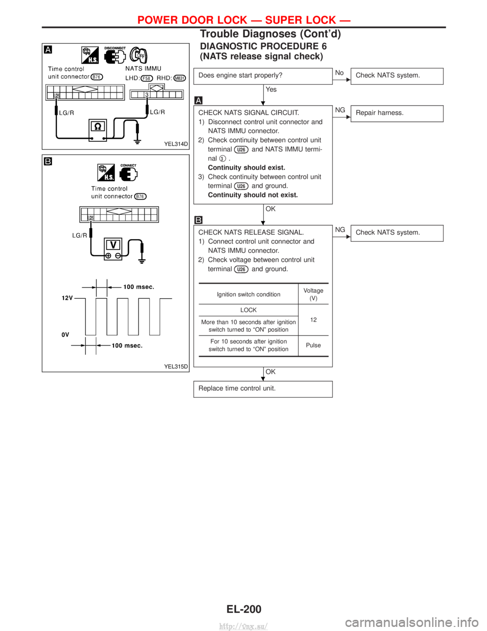
DIAGNOSTIC PROCEDURE 6
(NATS release signal check)
Does engine start properly?
Ye s
ENoCheck NATS system.
CHECK NATS SIGNAL CIRCUIT.
1) Disconnect control unit connector and
NATS IMMU connector.
2) Check continuity between control unit terminal
U26and NATS IMMU termi-
nal q
3.
Continuity should exist.
3) Check continuity between control unit terminal
U26and ground.
Continuity should not exist.
OK
ENG Repair harness.
CHECK NATS RELEASE SIGNAL.
1) Connect control unit connector and
NATS IMMU connector.
2) Check voltage between control unit terminal
U26and ground.
OK
ENG Check NATS system.
Replace time control unit.
Ignition switch condition Voltage
(V)
LOCK 12
More than 10 seconds after ignition
switch turned to ªONº position
For 10 seconds after ignition
switch turned to ªONº position Pulse
YEL314D
YEL315D
H
H
H
POWER DOOR LOCK Ð SUPER LOCK Ð
Trouble Diagnoses (Cont'd)
EL-200
http://vnx.su/