2004 NISSAN TERRANO turn signal
[x] Cancel search: turn signalPage 712 of 1833
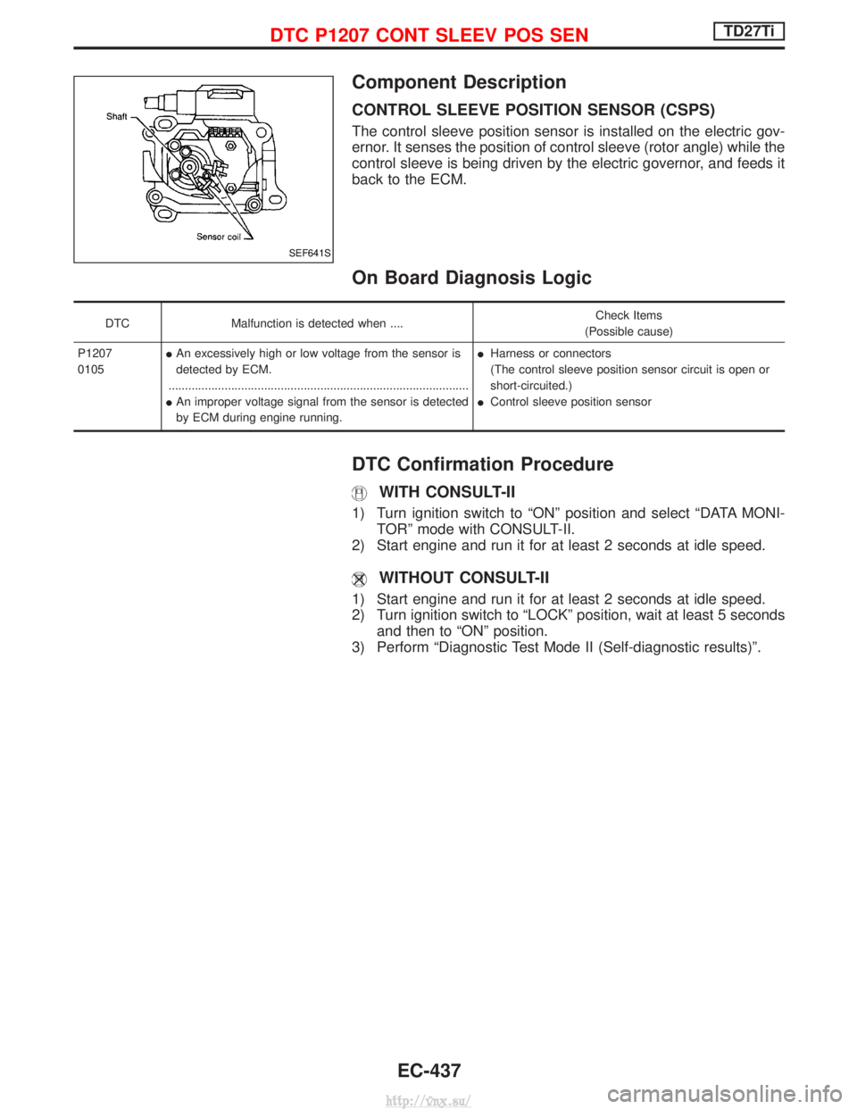
Component Description
CONTROL SLEEVE POSITION SENSOR (CSPS)
The control sleeve position sensor is installed on the electric gov-
ernor. It senses the position of control sleeve (rotor angle) while the
control sleeve is being driven by the electric governor, and feeds it
back to the ECM.
On Board Diagnosis Logic
DTCMalfunction is detected when .... Check Items
(Possible cause)
P1207
0105 I
An excessively high or low voltage from the sensor is
detected by ECM.
........................................................................\
...................
I An improper voltage signal from the sensor is detected
by ECM during engine running. I
Harness or connectors
(The control sleeve position sensor circuit is open or
short-circuited.)
I Control sleeve position sensor
DTC Confirmation Procedure
WITH CONSULT-II
1) Turn ignition switch to ªONº position and select ªDATA MONI-
TORº mode with CONSULT-II.
2) Start engine and run it for at least 2 seconds at idle speed.
WITHOUT CONSULT-II
1) Start engine and run it for at least 2 seconds at idle speed.
2) Turn ignition switch to ªLOCKº position, wait at least 5 seconds and then to ªONº position.
3) Perform ªDiagnostic Test Mode II (Self-diagnostic results)º.
SEF641S
DTC P1207 CONT SLEEV POS SENTD27Ti
EC-437
http://vnx.su/
Page 714 of 1833

Diagnostic Procedure
INSPECTION START
CHECK POWER SUPPLY CIRCUIT.
1. Turn ignition switch to ªLOCKº position.
2. Disconnect ECM harness connector and electrical fuel injection pump
harness connector.
3. Check harness continuity between electrical fuel injection pump terminal q
2
and ECM connector terminals321.
Refer to wiring diagram.
Continuity should exist.
If OK, check harness for short-circuit.
OK
ENG Check the following:
IHarness for open or
short-circuit between
ECM and control sleeve
position sensor.
If NG, repair harness or
connectors.
CHECK INPUT SIGNAL CIRCUIT.
1. Turn ignition switch to ªLOCKº position.
2. Check harness continuity between con- trol sleeve position sensor connector
terminal q
3and ECM connector termi-
nals
320. Refer to wiring diagram.
Continuity should exist.
If OK, check harness for short-circuit.
OK
ENG Check the following:
IHarness for open or
short-circuit between
ECM and control sleeve
position sensor.
If NG, repair harness or
connectors.
CHECK GROUND CIRCUIT-I.
Check harness continuity between electri-
cal fuel injection pump connector termi-
nals q
1and ECM connector terminals
322. Refer to wiring diagram.
Continuity should exist.
If OK, check harness for short-circuit.
OK
ENG Check the following:
IHarness for open or
short-circuit between
ECM and control sleeve
position sensor.
If NG, repair harness or
connectors.
CHECK GROUND CIRCUIT-II.
Check harness continuity between ECM
connector terminal
327and engine
ground. Refer to wiring diagram.
Continuity should exist.
If OK, check harness for short-circuit.
OK
ENG Check the following:
IHarness for open or
short-circuit.
If NG, repair harness or
connectors.
qA
YEC248A
H
H
H
H
H
DTC P1207 CONT SLEEV POS SENTD27Ti
EC-439
http://vnx.su/
Page 725 of 1833
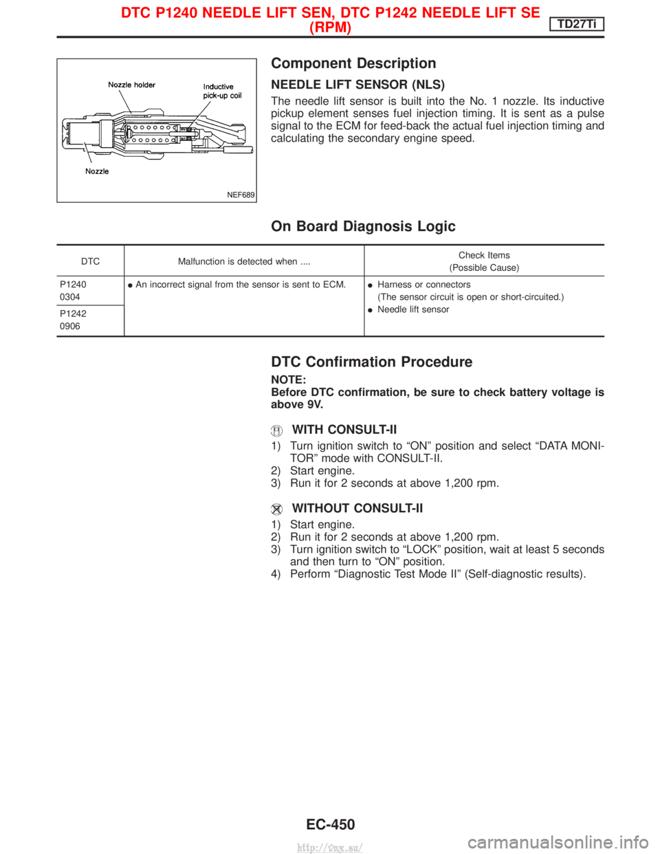
Component Description
NEEDLE LIFT SENSOR (NLS)
The needle lift sensor is built into the No. 1 nozzle. Its inductive
pickup element senses fuel injection timing. It is sent as a pulse
signal to the ECM for feed-back the actual fuel injection timing and
calculating the secondary engine speed.
On Board Diagnosis Logic
DTCMalfunction is detected when .... Check Items
(Possible Cause)
P1240
0304 I
An incorrect signal from the sensor is sent to ECM. IHarness or connectors
(The sensor circuit is open or short-circuited.)
I Needle lift sensor
P1242
0906
DTC Confirmation Procedure
NOTE:
Before DTC confirmation, be sure to check battery voltage is
above 9V.
WITH CONSULT-II
1) Turn ignition switch to ªONº position and select ªDATA MONI-
TORº mode with CONSULT-II.
2) Start engine.
3) Run it for 2 seconds at above 1,200 rpm.
WITHOUT CONSULT-II
1) Start engine.
2) Run it for 2 seconds at above 1,200 rpm.
3) Turn ignition switch to ªLOCKº position, wait at least 5 seconds and then turn to ªONº position.
4) Perform ªDiagnostic Test Mode IIº (Self-diagnostic results).
NEF689
DTC P1240 NEEDLE LIFT SEN, DTC P1242 NEEDLE LIFT SE (RPM)TD27Ti
EC-450
http://vnx.su/
Page 727 of 1833
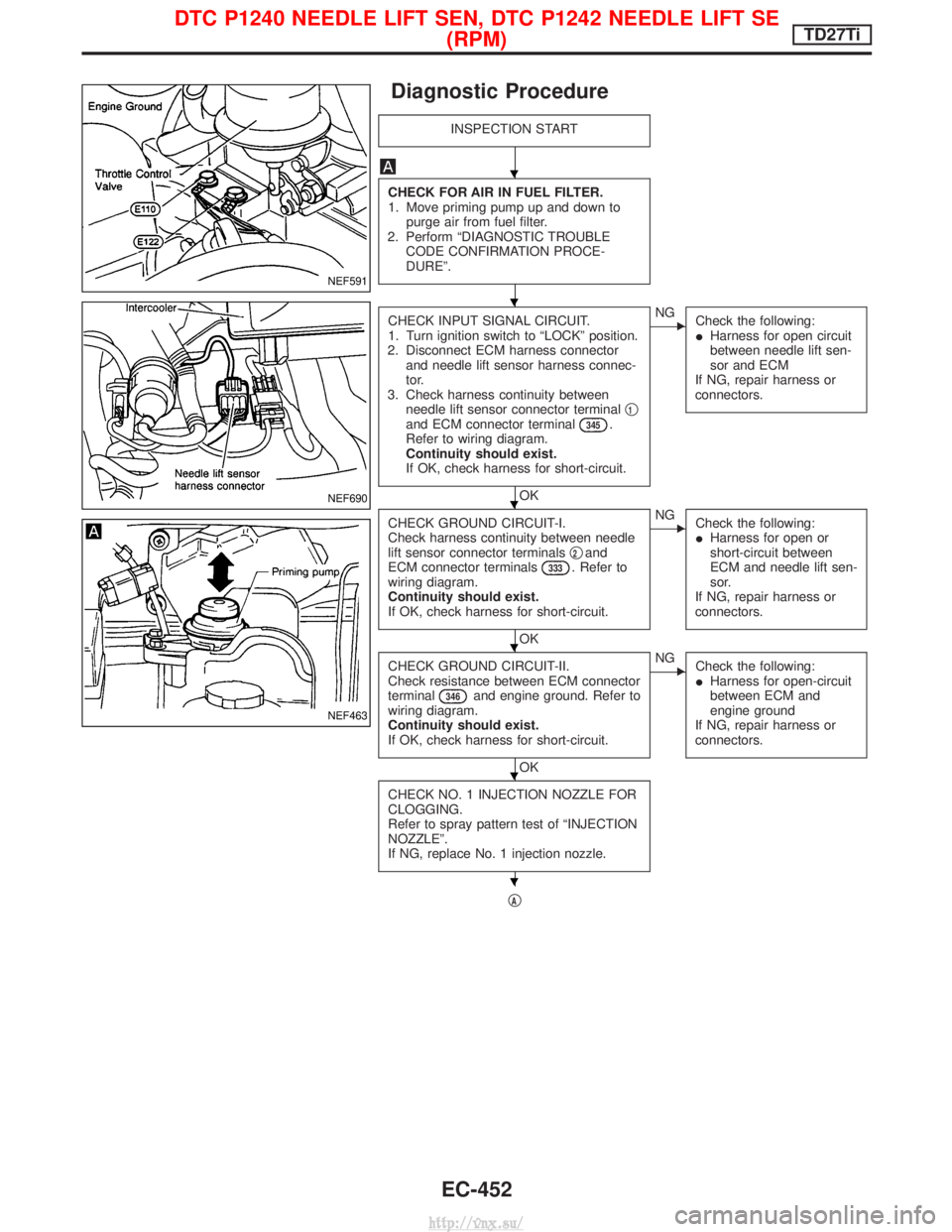
Diagnostic Procedure
INSPECTION START
CHECK FOR AIR IN FUEL FILTER.
1. Move priming pump up and down topurge air from fuel filter.
2. Perform ªDIAGNOSTIC TROUBLE CODE CONFIRMATION PROCE-
DUREº.
CHECK INPUT SIGNAL CIRCUIT.
1. Turn ignition switch to ªLOCKº position.
2. Disconnect ECM harness connector and needle lift sensor harness connec-
tor.
3. Check harness continuity between needle lift sensor connector terminal q
1and ECM connector terminal345.
Refer to wiring diagram.
Continuity should exist.
If OK, check harness for short-circuit.
OK
ENG Check the following:
IHarness for open circuit
between needle lift sen-
sor and ECM
If NG, repair harness or
connectors.
CHECK GROUND CIRCUIT-I.
Check harness continuity between needle
lift sensor connector terminals q
2and
ECM connector terminals333. Refer to
wiring diagram.
Continuity should exist.
If OK, check harness for short-circuit.
OK
ENG Check the following:
IHarness for open or
short-circuit between
ECM and needle lift sen-
sor.
If NG, repair harness or
connectors.
CHECK GROUND CIRCUIT-II.
Check resistance between ECM connector
terminal
346and engine ground. Refer to
wiring diagram.
Continuity should exist.
If OK, check harness for short-circuit.
OK
ENG Check the following:
IHarness for open-circuit
between ECM and
engine ground
If NG, repair harness or
connectors.
CHECK NO. 1 INJECTION NOZZLE FOR
CLOGGING.
Refer to spray pattern test of ªINJECTION
NOZZLEº.
If NG, replace No. 1 injection nozzle.
qA
NEF591
NEF690
NEF463
H
H
H
H
H
H
DTC P1240 NEEDLE LIFT SEN, DTC P1242 NEEDLE LIFT SE (RPM)TD27Ti
EC-452
http://vnx.su/
Page 736 of 1833
qB
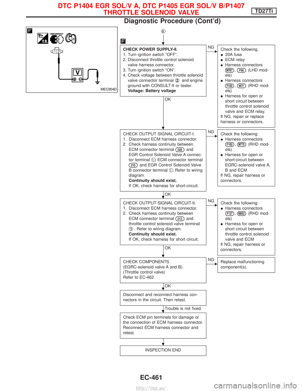
CHECK POWER SUPPLY-II.
1. Turn ignition switch ªOFFº.
2. Disconnect throttle control solenoid valve harness connector.
3. Turn ignition switch ªONº.
4. Check voltage between throttle solenoid valve connector terminal q
2and engine
ground with CONSULT-II or tester.
Voltage: Battery voltage
OK
ENG Check the following.
I20A fuse
I ECM relay
I Harness connectors
M787,F66(LHD mod-
els)
I Harness connectors
F100,M77(RHD mod-
els)
I Harness for open or
short circuit between
throttle control solenoid
valve and ECM relay.
If NG, repair or replace
harness or connectors.
CHECK OUTPUT SIGNAL CIRCUIT-I.
1. Disconnect ECM harness connector.
2. Check harness continuity between ECM connector terminal
208and
EGR Control Solenoid Valve A connec-
tor terminal q
1; ECM connector terminal
210and EGR Control Solenoid Valve
B connector terminal q
1. Refer to wiring
diagram.
Continuity should exist.
If OK, check harness for short-circuit.
OK
ENG Check the following:
IHarness connectors
F100,M775(RHD mod-
els)
I Harness for open or
short-circuit between
EGRC-solenoid valve A,
B and ECM
If NG, repair harness or
connectors.
CHECK OUTPUT SIGNAL CIRCUIT-II.
1. Disconnect ECM harness connector.
2. Check harness continuity between ECM connector terminal
213and
throttle control solenoid valve terminal
q
1. Refer to wiring diagram.
Continuity should exist.
If OK, check harness for short circuit.
OK
ENG Check the following:
IHarness connectors
F137,M853(RHD mod-
els)
I Harness for open or
short circuit between
throttle control solenoid
valve and ECM
If NG, repair harness or
connectors.
CHECK COMPONENTS
(EGRC-solenoid valve A and B).
(Throttle control valve)
Refer to EC-462.
OK
ENG Replace malfunctioning
component(s).
Disconnect and reconnect harness con-
nectors in the circuit. Then retest.
Trouble is not fixed.
Check ECM pin terminals for damage or
the connection of ECM harness connector.
Reconnect ECM harness connector and
retest.
INSPECTION END
MEC954D
H
H
H
H
H
H
H
DTC P1404 EGR SOL/V A, DTC P1405 EGR SOL/V B/P1407 THROTTLE SOLENOID VALVETD27Ti
Diagnostic Procedure (Cont'd)
EC-461
http://vnx.su/
Page 738 of 1833
Component Description
AIR CONDITIONER CUT CONTROL
Air conditioner is cut under the following conditions:
IStarting engine
I Quick acceleration from low speed
I Undershooting of idle speed
I High engine coolant temperature [above 107ÉC (225ÉF)]
I Malfunctioning of engine speed sensor, accelerator position sen-
sor or vehicle speed sensor when engine speed is below 2,100
rpm.
On Board Diagnosis Logic
DTC Malfunction is detected when .... Check Items
(Possible cause)
P1530
0805 I
Air conditioner relay signal circuit is shorted. IHarness or connectors
(The air conditioner relay signal circuit is shorted.)
I Air conditioner relay
DTC Confirmation Procedure
WITH CONSULT-II
1) Turn ignition switch and air conditioner switch to ªONº position.
2) Select ªDATA MONITORº mode with CONSULT-II.
3) Wait at least 2 seconds.
WITHOUT CONSULT-II
1) Turn ignition switch and air conditioner switch to ªONº position.
Wait at least 2 seconds.
2) Turn ignition switch to ªLOCKº position, wait at least 5 seconds and then turn to ªONº position.
3) Perform ªDiagnostic Test Mode IIº (Self-diagnostic results).
DTC P1530 AIR CONDITIONER RLYTD27Ti
EC-463
http://vnx.su/
Page 741 of 1833
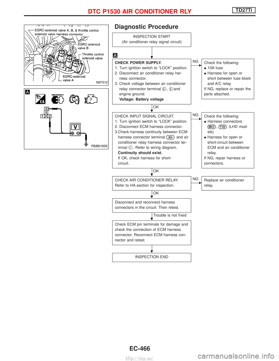
Diagnostic Procedure
INSPECTION START
(Air conditioner relay signal circuit)
CHECK POWER SUPPLY.
1. Turn ignition switch to ªLOCKº position.
2. Disconnect air conditioner relay har- ness connector.
3. Check voltage between air conditioner relay connector terminal q
2,q3and
engine ground.
Voltage: Battery voltage
OK
ENG Check the following:
I10A fuse
I Harness for open or
short between fuse block
and A/C relay
If NG, replace or repair the
parts attached.
CHECK INPUT SIGNAL CIRCUIT.
1. Turn ignition switch to ªLOCKº position.
2. Disconnect ECM harness connector.
3.Check harness continuity between ECM harness connector terminal
204and air
conditioner relay harness connector ter-
minal q
1. Refer to wiring diagram.
Continuity should exist.
If OK, check harness for short-
circuit.
OK
ENG Check the following:
IHarness connectors
M812,F120(LHD mod-
els)
I Harness for open or
short-circuit between
ECM and air conditioner
relay.
If NG, repair harness or
connectors.
CHECK AIR CONDITIONER RELAY.
Refer to HA section for inspection.
OK
ENG Replace air conditioner
relay.
Disconnect and reconnect harness
connectors in the circuit. Then retest.
Trouble is not fixed
Check ECM pin terminals for damage and
check the connection of ECM harness
connector. Reconnect ECM harness con-
nector and retest.
INSPECTION END
NEF512
PBIB0185E
H
H
H
H
H
H
DTC P1530 AIR CONDITIONER RLYTD27Ti
EC-466
http://vnx.su/
Page 742 of 1833
Description
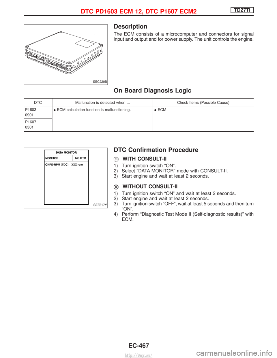
The ECM consists of a microcomputer and connectors for signal
input and output and for power supply. The unit controls the engine.
On Board Diagnosis Logic
DTCMalfunction is detected when ... Check Items (Possible Cause)
P1603
0901 I
ECM calculation function is malfunctioning. IECM
P1607
0301
DTC Confirmation Procedure
WITH CONSULT-II
1) Turn ignition switch ªONº.
2) Select ªDATA MONITORº mode with CONSULT-II.
3) Start engine and wait at least 2 seconds.
WITHOUT CONSULT-II
1) Turn ignition switch ªONº and wait at least 2 seconds.
2) Start engine and wait at least 2 seconds.
3) Turn ignition switch ªOFFº, wait at least 5 seconds and then turn ªONº.
4) Perform ªDiagnostic Test Mode II (Self-diagnostic results)º with ECM.
SEC220B
SEF817Y
DTC PD1603 ECM 12, DTC P1607 ECM2TD27Ti
EC-467
http://vnx.su/