2004 NISSAN TERRANO turn signal
[x] Cancel search: turn signalPage 641 of 1833

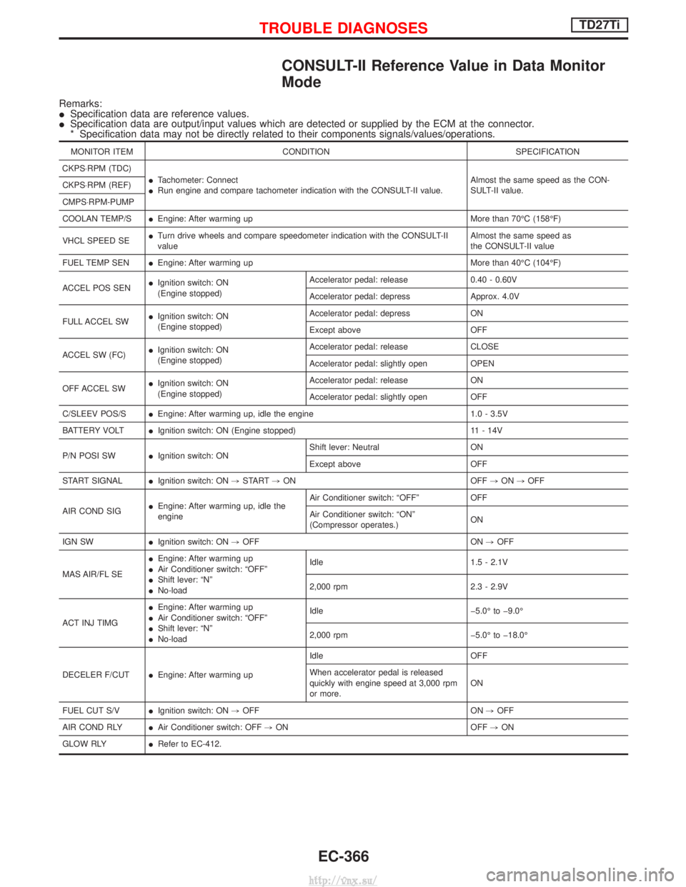
CONSULT-II Reference Value in Data Monitor
Mode
Remarks:
ISpecification data are reference values.
I Specification data are output/input values which are detected or supplied by the ECM at the connector.
* Specification data may not be directly related to their components signals/values/operations.
MONITOR ITEM CONDITION SPECIFICATION
CKPS×RPM (TDC) ITachometer: Connect
I Run engine and compare tachometer indication with the CONSULT-II value. Almost the same speed as the CON-
SULT-II value.
CKPS×RPM (REF)
CMPS×RPM-PUMP
COOLAN TEMP/S
IEngine: After warming up More than 70ÉC (158ÉF)
VHCL SPEED SE I
Turn drive wheels and compare speedometer indication with the CONSULT-II
value Almost the same speed as
the CONSULT-II value
FUEL TEMP SEN IEngine: After warming up More than 40ÉC (104ÉF)
ACCEL POS SEN I
Ignition switch: ON
(Engine stopped) Accelerator pedal: release 0.40 - 0.60V
Accelerator pedal: depress Approx. 4.0V
FULL ACCEL SW I
Ignition switch: ON
(Engine stopped) Accelerator pedal: depress ON
Except above OFF
ACCEL SW (FC) I
Ignition switch: ON
(Engine stopped) Accelerator pedal: release CLOSE
Accelerator pedal: slightly open OPEN
OFF ACCEL SW I
Ignition switch: ON
(Engine stopped) Accelerator pedal: release ON
Accelerator pedal: slightly open OFF
C/SLEEV POS/S IEngine: After warming up, idle the engine 1.0 - 3.5V
BATTERY VOLT IIgnition switch: ON (Engine stopped) 11 - 14V
P/N POSI SW IIgnition switch: ON Shift lever: Neutral ON
Except above OFF
START SIGNAL IIgnition switch: ON ,START ,ON OFF ,ON ,OFF
AIR COND SIG I
Engine: After warming up, idle the
engine Air Conditioner switch: ªOFFº OFF
Air Conditioner switch: ªONº
(Compressor operates.)
ON
IGN SW IIgnition switch: ON ,OFF ON ,OFF
MAS AIR/FL SE I
Engine: After warming up
I Air Conditioner switch: ªOFFº
I Shift lever: ªNº
I No-load Idle 1.5 - 2.1V
2,000 rpm 2.3 - 2.9V
ACT INJ TIMG I
Engine: After warming up
I Air Conditioner switch: ªOFFº
I Shift lever: ªNº
I No-load Idle þ5.0É to þ9.0É
2,000 rpm þ5.0É to þ18.0É
DECELER F/CUT IEngine: After warming up Idle OFF
When accelerator pedal is released
quickly with engine speed at 3,000 rpm
or more.
ON
FUEL CUT S/V IIgnition switch: ON ,OFF ON ,OFF
AIR COND RLY IAir Conditioner switch: OFF ,ON OFF ,ON
GLOW RLY IRefer to EC-412.
TROUBLE DIAGNOSESTD27Ti
EC-366
http://vnx.su/
Page 647 of 1833
![NISSAN TERRANO 2004 Service Repair Manual TERMI-NALNO. WIRE
COLOR ITEM CONDITION DATA (DC Voltage and
Pulse Signal)
322 B Control sleeve position
sensor ground [Engine is running]
I
Idle speed Approximately 2.6V
NEF476
325 L ECM relay (Self-s NISSAN TERRANO 2004 Service Repair Manual TERMI-NALNO. WIRE
COLOR ITEM CONDITION DATA (DC Voltage and
Pulse Signal)
322 B Control sleeve position
sensor ground [Engine is running]
I
Idle speed Approximately 2.6V
NEF476
325 L ECM relay (Self-s](/manual-img/5/57394/w960_57394-646.png)
TERMI-NALNO. WIRE
COLOR ITEM CONDITION DATA (DC Voltage and
Pulse Signal)
322 B Control sleeve position
sensor ground [Engine is running]
I
Idle speed Approximately 2.6V
NEF476
325 L ECM relay (Self-shutoff)
[Ignition switch ªONº]
[Ignition switch ªOFFº]
I
For a few seconds after turning ignition switch
ªOFFº Approximately 1.4V
[Ignition switch ªOFFº]
I A few seconds passed after turning ignition switch
ªOFFº BATTERY VOLTAGE
(11 - 14V)
331 L/R Crankshaft position sensor
(TDC) ground [Engine is running]
I
Warm-up condition
I Idle speed Approximately 0V
333 R Needle lift sensor ground [Ignition switch ªONº] Approximately 0V
334 G/R Engine coolant tempera-
ture sensor ground [Ignition switch ªONº]
Approximately 0V
335 G/R Fuel temperature sensor
ground [Engine is running]
Approximately 0V
344 L/G Crankshaft position sensor
(TDC) [Engine is running]
I
Warm-up condition
I Idle speed Approximately 0V
SEF333Y
[Engine is running]
I
Warm-up condition
I Engine speed is 2,000 rpm Approximately 0V
SEF334Y
345 G Needle lift sensor
[Engine is running]
I
Warm-up condition
I Idle speed Approximately 3.5V
[Engine is running]
I Warm-up condition
I Engine speed is 2,000 rpm Approximately 3.5V
TROUBLE DIAGNOSESTD27Ti
ECM Terminals and Reference Value (Cont'd)
EC-372
http://vnx.su/
Page 648 of 1833
![NISSAN TERRANO 2004 Service Repair Manual TERMI-NALNO. WIRE
COLOR ITEM CONDITION DATA (DC Voltage and
Pulse Signal)
347 LG/W Engine coolant tempera-
ture sensor [Engine is running] Approximately 0 - 4.8V
Output voltage varies with
engine cool NISSAN TERRANO 2004 Service Repair Manual TERMI-NALNO. WIRE
COLOR ITEM CONDITION DATA (DC Voltage and
Pulse Signal)
347 LG/W Engine coolant tempera-
ture sensor [Engine is running] Approximately 0 - 4.8V
Output voltage varies with
engine cool](/manual-img/5/57394/w960_57394-647.png)
TERMI-NALNO. WIRE
COLOR ITEM CONDITION DATA (DC Voltage and
Pulse Signal)
347 LG/W Engine coolant tempera-
ture sensor [Engine is running] Approximately 0 - 4.8V
Output voltage varies with
engine coolant tempera-
ture
348 Y/B Fuel temperature sensor [Engine is running] 0.6-5V
Output voltage varies with
fuel temperature.
349 G/R Injection timing control
valve ground [Ignition switch ªONº]
Approximately 0V
403 G/R Air conditioner switch [Engine is running]
I
Air conditioner switch is ªOFFº BATTERY VOLTAGE
(11 - 14V)
[Engine is running]
I Both air conditioner switch and blower fan switch
are ªONº
(Compressor is operating) Approximately 0.1V
405 G/Y Stop lamp switch [Ignition switch ªONº]
I
Brake pedal fully released Approximately 0V
[Ignition switch ªONº]
I Brake pedal depressed BATTERY VOLTAGE
(11 - 14V)
416 Y/R Brake pedal position
switch [Ignition switch ªONº]
I
Brake pedal fully released BATTERY VOLTAGE
(11 - 14V)
[Ignition switch ªONº]
I Brake pedal depressed Approximately 0V
415 OR Data link connector for
CONSULT-II [Engine is running]
I
Idle speed (CONSULT-II is connected and turned
on) Approximately 0V
420 R BATTERY VOLTAGE
(11 - 14V)
417 Y/B Vehicle speed sensor [Engine is running]
I
Lift up the vehicle
I In 1st gear position
I Vehicle speed is 10 km/h (6 MPH) 0 - Approximately 8V
SEF891Y
[Engine is running]
I
Lift up the vehicle
I In 2nd gear position
I Vehicle speed is 30 km/h (19 MPH) Approximately 6V
SEF892Y
422 PU Start signal
[Ignition switch ªONº]
Approximately 0V
[Ignition switch ªSTARTº] BATTERY VOLTAGE
(11 - 14V)
425 R/B Accelerator position sen-
sor ground [Engine is running]
I
Warm-up condition
I Idle speed Approximately 0V
TROUBLE DIAGNOSESTD27Ti
ECM Terminals and Reference Value (Cont'd)
EC-373
http://vnx.su/
Page 654 of 1833

Component Description
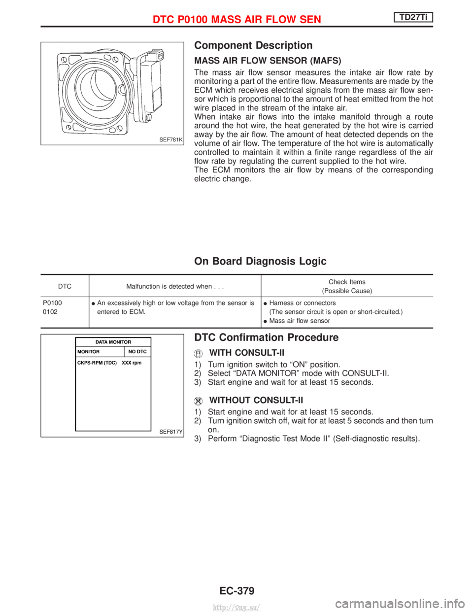
MASS AIR FLOW SENSOR (MAFS)
The mass air flow sensor measures the intake air flow rate by
monitoring a part of the entire flow. Measurements are made by the
ECM which receives electrical signals from the mass air flow sen-
sor which is proportional to the amount of heat emitted from the hot
wire placed in the stream of the intake air.
When intake air flows into the intake manifold through a route
around the hot wire, the heat generated by the hot wire is carried
away by the air flow. The amount of heat detected depends on the
volume of air flow. The temperature of the hot wire is automatically
controlled to maintain it within a finite range regardless of the air
flow rate by regulating the current supplied to the hot wire.
The ECM monitors the air flow by means of the corresponding
electric change.
On Board Diagnosis Logic
DTCMalfunction is detected when... Check Items
(Possible Cause)
P0100
0102 I
An excessively high or low voltage from the sensor is
entered to ECM. I
Harness or connectors
(The sensor circuit is open or short-circuited.)
I Mass air flow sensor
DTC Confirmation Procedure
WITH CONSULT-II
1) Turn ignition switch to ªONº position.
2) Select ªDATA MONITORº mode with CONSULT-II.
3) Start engine and wait for at least 15 seconds.
WITHOUT CONSULT-II
1) Start engine and wait for at least 15 seconds.
2) Turn ignition switch off, wait for at least 5 seconds and then turn
on.
3) Perform ªDiagnostic Test Mode IIº (Self-diagnostic results).
SEF781K
SEF817Y
DTC P0100 MASS AIR FLOW SENTD27Ti
EC-379
http://vnx.su/
Page 657 of 1833

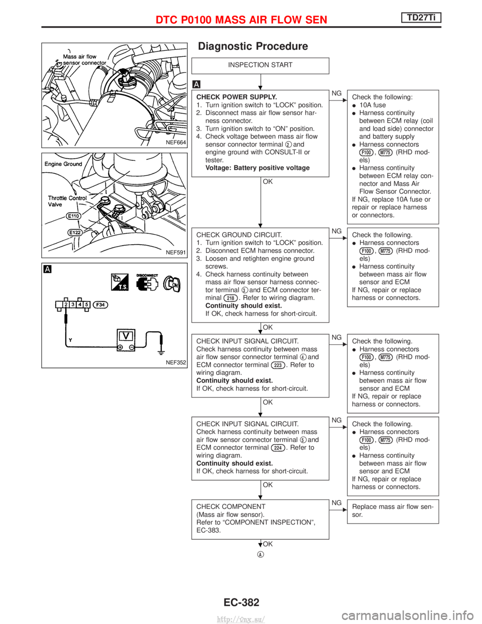
Diagnostic Procedure
INSPECTION START
CHECK POWER SUPPLY.
1. Turn ignition switch to ªLOCKº position.
2. Disconnect mass air flow sensor har- ness connector.
3. Turn ignition switch to ªONº position.
4. Check voltage between mass air flow sensor connector terminal q
2and
engine ground with CONSULT-II or
tester.
Voltage: Battery positive voltage
OK
ENG Check the following:
I10A fuse
I Harness continuity
between ECM relay (coil
and load side) connector
and battery supply
I Harness connectors
F100,M775(RHD mod-
els)
I Harness continuity
between ECM relay con-
nector and Mass Air
Flow Sensor Connector.
If NG, replace 10A fuse or
repair or replace harness
or connectors.
CHECK GROUND CIRCUIT.
1. Turn ignition switch to ªLOCKº position.
2. Disconnect ECM harness connector.
3. Loosen and retighten engine ground screws.
4. Check harness continuity between mass air flow sensor harness connec-
tor terminal q
3and ECM connector ter-
minal218. Refer to wiring diagram.
Continuity should exist.
If OK, check harness for short-circuit.
OK
ENG Check the following.
IHarness connectors
F100,M775(RHD mod-
els)
I Harness continuity
between mass air flow
sensor and ECM
If NG, repair or replace
harness or connectors.
CHECK INPUT SIGNAL CIRCUIT.
Check harness continuity between mass
air flow sensor connector terminal q
4and
ECM connector terminal223. Refer to
wiring diagram.
Continuity should exist.
If OK, check harness for short-circuit.
OK
ENG Check the following.
IHarness connectors
F100,M775(RHD mod-
els)
I Harness continuity
between mass air flow
sensor and ECM
If NG, repair or replace
harness or connectors.
CHECK INPUT SIGNAL CIRCUIT.
Check harness continuity between mass
air flow sensor connector terminal q
5and
ECM connector terminal224. Refer to
wiring diagram.
Continuity should exist.
If OK, check harness for short-circuit.
OK
ENG Check the following.
IHarness connectors
F100,M775(RHD mod-
els)
I Harness continuity
between mass air flow
sensor and ECM
If NG, repair or replace
harness or connectors.
CHECK COMPONENT
(Mass air flow sensor).
Refer to ªCOMPONENT INSPECTIONº,
EC-383.
OK
ENG Replace mass air flow sen-
sor.
qA
NEF664
NEF591
NEF352
H
H
H
H
H
H
DTC P0100 MASS AIR FLOW SENTD27Ti
EC-382
http://vnx.su/
Page 659 of 1833

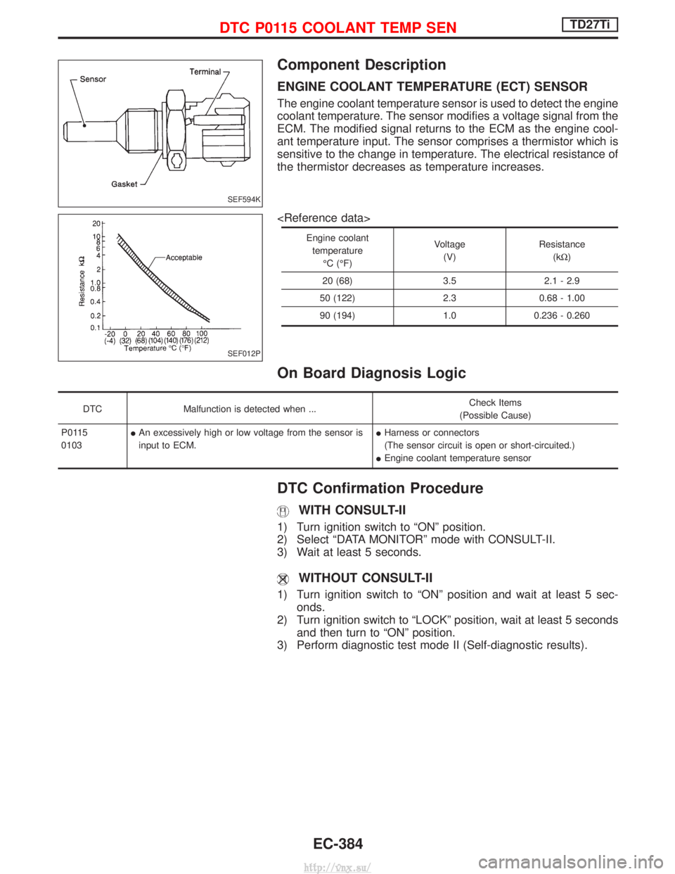
Component Description
ENGINE COOLANT TEMPERATURE (ECT) SENSOR
The engine coolant temperature sensor is used to detect the engine
coolant temperature. The sensor modifies a voltage signal from the
ECM. The modified signal returns to the ECM as the engine cool-
ant temperature input. The sensor comprises a thermistor which is
sensitive to the change in temperature. The electrical resistance of
the thermistor decreases as temperature increases.
Engine coolanttemperature ÉC (ÉF) Voltage
(V) Resistance
(kW )
20 (68) 3.5 2.1 - 2.9
50 (122) 2.3 0.68 - 1.00
90 (194) 1.0 0.236 - 0.260
On Board Diagnosis Logic
DTC Malfunction is detected when ... Check Items
(Possible Cause)
P0115
0103 I
An excessively high or low voltage from the sensor is
input to ECM. I
Harness or connectors
(The sensor circuit is open or short-circuited.)
I Engine coolant temperature sensor
DTC Confirmation Procedure
WITH CONSULT-II
1) Turn ignition switch to ªONº position.
2) Select ªDATA MONITORº mode with CONSULT-II.
3) Wait at least 5 seconds.
WITHOUT CONSULT-II
1) Turn ignition switch to ªONº position and wait at least 5 sec-
onds.
2) Turn ignition switch to ªLOCKº position, wait at least 5 seconds and then turn to ªONº position.
3) Perform diagnostic test mode II (Self-diagnostic results).
SEF594K
SEF012P
DTC P0115 COOLANT TEMP SENTD27Ti
EC-384
http://vnx.su/
Page 663 of 1833

Component Description
ACCELERATOR WORK UNIT
The accelerator position sensor is installed on the upper end of the
accelerator pedal assembly. The sensor detects the accelerator
position and sends a signal to the ECM. The ECM uses the signal
to determine the amount of fuel to be injected.
The accelerator position switch is installed inside the accelerator
position sensor. This switch is used for plausibility check of the
accelerator position sensor.
On Board Diagnosis Logic
DTCMalfunction is detected when ... Check Items
(Possible Cause)
P0120
0403 I
An excessively low or high voltage from the sensor is
detected by the ECM. I
Harness or connectors
(The sensor or switch circuit is open or
short-circuited.)
I Accelerator position sensor
I Accelerator position switch
DTC Confirmation Procedure A (For General
Plausibility)
WITH CONSULT-II
1) Turn ignition switch to ªONº position.
2) Select ªDATA MONITORº mode with CONSULT-II.
3) Depress accelerator pedal fully and keep it for at least 1 sec-
ond. Then release it and wait at least 5 seconds.
WITHOUT CONSULT-II
1) Turn ignition switch to ªONº position.
2) Depress accelerator pedal fully and keep it for at least 1 sec-ond. Then release it and wait at least 5 seconds.
3) Turn ignition switch to ªLOCKº position, wait at least 5 seconds and then turn to ªONº position.
4) Perform ªDiagnostic Test Mode II (Self-diagnostic results)º with ECM.
MEC959D
DTC P0120 ACCEL POS SENSORTD27Ti
EC-388
http://vnx.su/
Page 666 of 1833

Diagnostic Procedure
ACCELERATOR POSITION SENSOR
INSPECTION START
CHECK POWER SUPPLY.
1. Turn ignition switch to ªLOCKº position.
2. Disconnect accelerator work unit har- ness connector.
3. Turn ignition switch to ªONº position.
4. Check voltage between accelerator work unit connector terminal q
2and
engine ground with CONSULT-II or
tester.
Voltage: Approximately 5V
OK
ENG Check the following:
IHarness for open or
short-circuit between
ECM and accelerator
work unit.
If NG, repair harness or
connectors.
CHECK INPUT SIGNAL CIRCUIT.
1. Turn ignition switch to ªLOCKº position.
2. Loosen and retighten engine ground screws.
3. Check harness continuity between accelerator work unit connector termi-
nal q
4and ECM connector terminal
434. Refer to wiring diagram.
Continuity should exist.
If OK, check harness for short-circuit.
OK
ENG Check the following:
IHarness for open-circuit
between ECM and
accelerator work unit
If NG, repair harness or
connectors.
CHECK GROUND CIRCUIT.
1. Disconnect ECM harness connector.
2. Check harness continuity between ECM terminal
425and accelerator
position sensor connector terminal q
3.
Refer to wiring diagram.
Continuity should exist.
If OK, check harness for short-circuit.
OK
ENG Repair harness or connec-
tors.
CHECK COMPONENT
(Accelerator position sensor).
Refer to ªCOMPONENT INSPECTIONº on
page EC-394.
OK
ENGReplace accelerator pedal
assembly.
Disconnect and reconnect harness con-
nectors in the circuit. Then retest.
Trouble is not fixed.
Check ECM pin terminals for damage and
check the connection of ECM harness
connector. Reconnect ECM harness con-
nector and retest.
INSPECTION END
NEF700
NEF591
YEC698A
H
H
H
H
H
H
H
DTC P0120 ACCEL POS SENSORTD27Ti
EC-391
http://vnx.su/