Page 570 of 1833
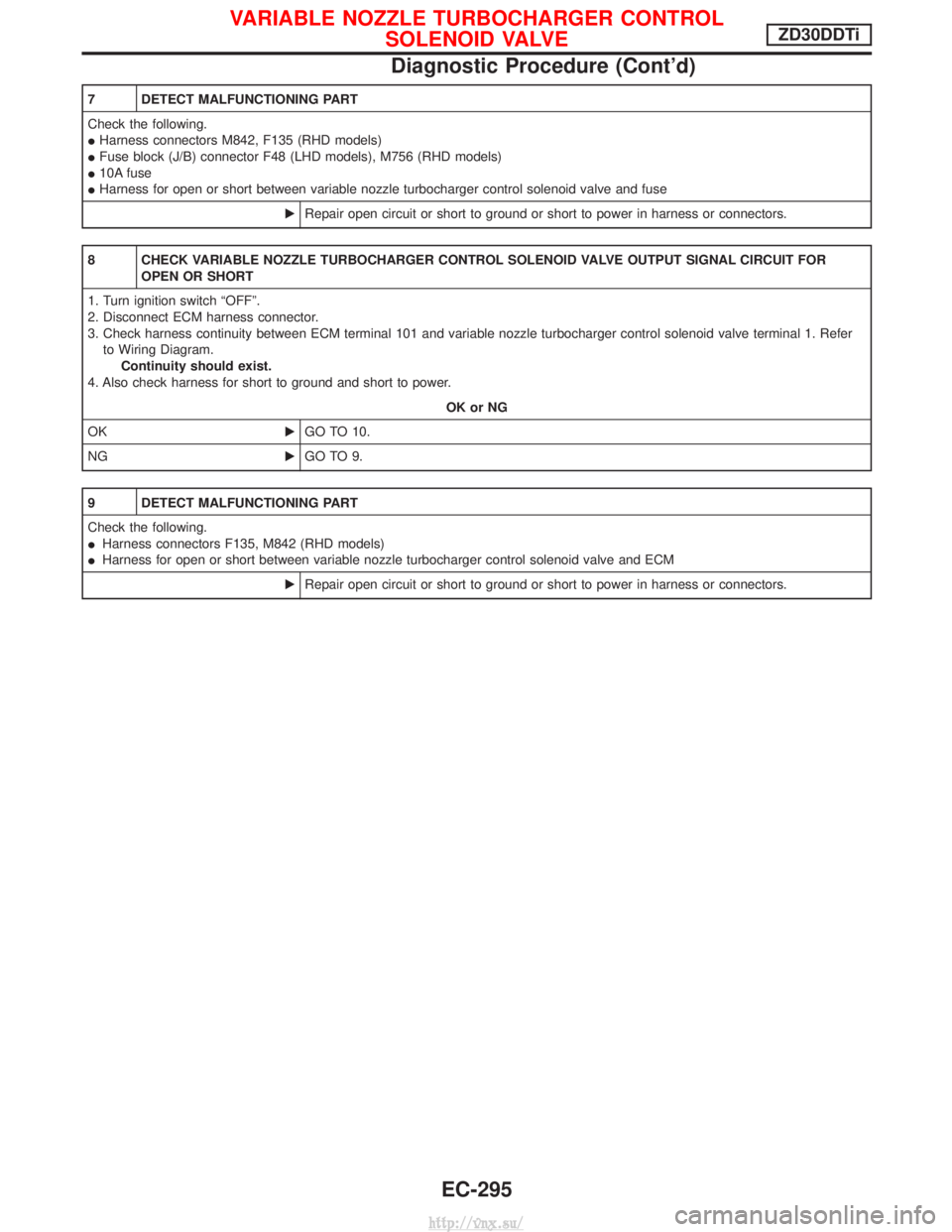
7 DETECT MALFUNCTIONING PART
Check the following.
IHarness connectors M842, F135 (RHD models)
I Fuse block (J/B) connector F48 (LHD models), M756 (RHD models)
I 10A fuse
I Harness for open or short between variable nozzle turbocharger control solenoid valve and fuse
ERepair open circuit or short to ground or short to power in harness or connectors.
8 CHECK VARIABLE NOZZLE TURBOCHARGER CONTROL SOLENOID VALVE OUTPUT SIGNAL CIRCUIT FOR
OPEN OR SHORT
1. Turn ignition switch ªOFFº.
2. Disconnect ECM harness connector.
3. Check harness continuity between ECM terminal 101 and variable nozzle turbocharger control solenoid valve terminal 1. Refer to Wiring Diagram. Continuity should exist.
4. Also check harness for short to ground and short to power.
OK or NG
OK EGO TO 10.
NG EGO TO 9.
9 DETECT MALFUNCTIONING PART
Check the following.
IHarness connectors F135, M842 (RHD models)
I Harness for open or short between variable nozzle turbocharger control solenoid valve and ECM
ERepair open circuit or short to ground or short to power in harness or connectors.
VARIABLE NOZZLE TURBOCHARGER CONTROL
SOLENOID VALVEZD30DDTi
Diagnostic Procedure (Cont'd)
EC-295
http://vnx.su/
Page 572 of 1833
Component Description
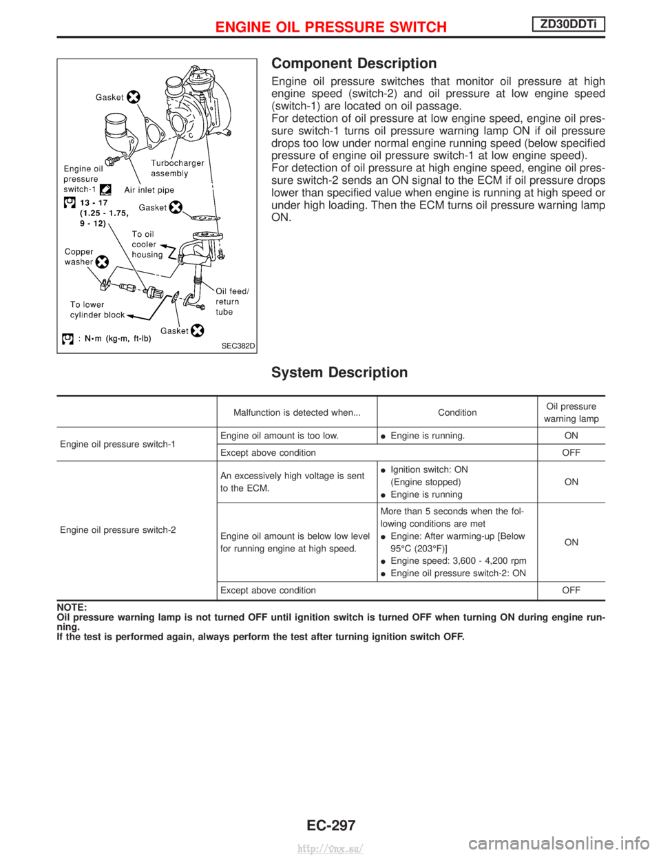
Engine oil pressure switches that monitor oil pressure at high
engine speed (switch-2) and oil pressure at low engine speed
(switch-1) are located on oil passage.
For detection of oil pressure at low engine speed, engine oil pres-
sure switch-1 turns oil pressure warning lamp ON if oil pressure
drops too low under normal engine running speed (below specified
pressure of engine oil pressure switch-1 at low engine speed).
For detection of oil pressure at high engine speed, engine oil pres-
sure switch-2 sends an ON signal to the ECM if oil pressure drops
lower than specified value when engine is running at high speed or
under high loading. Then the ECM turns oil pressure warning lamp
ON.
System Description
Malfunction is detected when...ConditionOil pressure
warning lamp
Engine oil pressure switch-1 Engine oil amount is too low.
IEngine is running. ON
Except above condition OFF
Engine oil pressure switch-2 An excessively high voltage is sent
to the ECM.
I
Ignition switch: ON
(Engine stopped)
I Engine is running ON
Engine oil amount is below low level
for running engine at high speed. More than 5 seconds when the fol-
lowing conditions are met
I
Engine: After warming-up [Below
95ÉC (203ÉF)]
I Engine speed: 3,600 - 4,200 rpm
I Engine oil pressure switch-2: ON ON
Except above condition OFF
NOTE:
Oil pressure warning lamp is not turned OFF until ignition switch is turned OFF when turning ON during engine run-
ning.
If the test is performed again, always perform the test after turning ignition switch OFF.
SEC382D
ENGINE OIL PRESSURE SWITCHZD30DDTi
EC-297
http://vnx.su/
Page 577 of 1833
6 CHECK ECM OUTPUT SIGNAL CIRCUIT
1. Turn ignition switch ªOFFº.
2. Disconnect ECM harness connector.
3. Disconnect combination meter harness connector.
4. Check harness continuity between ECM terminal 6 and combination meter terminal 16.Refer to Wiring Diagram.
Continuity should exist.
5. Also check harness for short to ground or short to power.
OK or NG
OK EINSPECTION END
NG EGO TO 7.
7 DETECT MALFUNCTIONING PART
Check the following.
IHarness for open or short between ECM and combination meter
ERepair open circuit or short to ground or short to power in harness or connectors.
8 CHECK COMBINATION METER POWER SUPPLY CIRCUIT
1. Turn ignition switch ªOFFº.
2. Disconnect combination meter harness connector.
3. Turn ignition switch ªONº.
4. Check voltage between combination meter terminal 28 and ground.
YEC701AVoltage: Battery voltage
OK or NG
OK EGO TO 10.
NG EGO TO 9.
ENGINE OIL PRESSURE SWITCHZD30DDTi
Diagnostic Procedure (Cont'd)
EC-302
http://vnx.su/
Page 578 of 1833
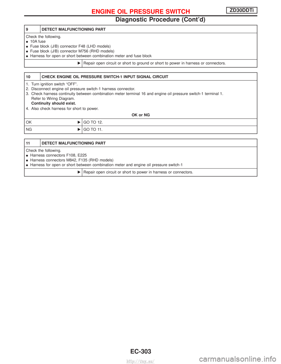
9 DETECT MALFUNCTIONING PART
Check the following.
I10A fuse
I Fuse block (J/B) connector F48 (LHD models)
I Fuse block (J/B) connector M756 (RHD models)
I Harness for open or short between combination meter and fuse block
ERepair open circuit or short to ground or short to power in harness or connectors.
10 CHECK ENGINE OIL PRESSURE SWITCH-1 INPUT SIGNAL CIRCUIT
1. Turn ignition switch ªOFFº.
2. Disconnect engine oil pressure switch-1 harness connector.
3. Check harness continuity between combination meter terminal 16 and engine oil pressure switch-1 terminal 1.
Refer to Wiring Diagram.
Continuity should exist.
4. Also check harness for short to power.
OK or NG
OK EGO TO 12.
NG EGO TO 11.
11 DETECT MALFUNCTIONING PART
Check the following.
IHarness connectors F108, E225
I Harness connectors M842, F135 (RHD models)
I Harness for open or short between combination meter and engine oil pressure switch-1
ERepair open circuit or short to power in harness or connectors.
ENGINE OIL PRESSURE SWITCHZD30DDTi
Diagnostic Procedure (Cont'd)
EC-303
http://vnx.su/
Page 580 of 1833
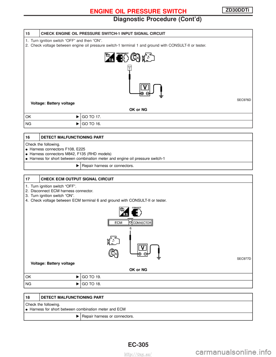
15 CHECK ENGINE OIL PRESSURE SWITCH-1 INPUT SIGNAL CIRCUIT
1. Turn ignition switch ªOFFº and then ªONº.
2. Check voltage between engine oil pressure switch-1 terminal 1 and ground with CONSULT-II or tester.
SEC976DVoltage: Battery voltageOK or NG
OK EGO TO 17.
NG EGO TO 16.
16 DETECT MALFUNCTIONING PART
Check the following.
IHarness connectors F108, E225
I Harness connectors M842, F135 (RHD models)
I Harness for short between combination meter and engine oil pressure switch-1
ERepair harness or connectors.
17 CHECK ECM OUTPUT SIGNAL CIRCUIT
1. Turn ignition switch ªOFFº.
2. Disconnect ECM harness connector.
3. Turn ignition switch ªONº.
4. Check voltage between ECM terminal 6 and ground with CONSULT-II or tester.
SEC977D
Voltage: Battery voltage
OK or NG
OK EGO TO 19.
NG EGO TO 18.
18 DETECT MALFUNCTIONING PART
Check the following.
IHarness for short between combination meter and ECM
ERepair harness or connectors.
ENGINE OIL PRESSURE SWITCHZD30DDTi
Diagnostic Procedure (Cont'd)
EC-305
http://vnx.su/
Page 581 of 1833
19 CHECK ENGINE OIL PRESSURE SWITCH-2 INPUT SIGNAL CIRCUIT
1. Turn ignition switch ªOFFº.
2. Disconnect engine oil pressure switch-2 harness connector.
3. Turn ignition switch ªONº.
4. Check voltage between engine oil pressure switch-2 terminal 1 and ground with CONSULT-II or tester.
SEC976D
Voltage: Battery voltageOK or NG
OK EGO TO 21.
NG EGO TO 20.
20 DETECT MALFUNCTIONING PART
Check the following.
IHarness connectors M807, E201
I Harness connectors F120, M812 (LHD models)
I Resistor
I 10A fuse
I Fuse block (J/B) connector F48 (LHD models)
I Fuse block (J/B) connector M756 (RHD models)
I Harness for open between engine oil pressure switch-2 and fuse
ERepair harness or connectors.
21 CHECK ECM INPUT SIGNAL CIRCUIT-I
Check voltage between ECM terminal 27 and ground with CONSULT-II or tester.
SEC388DVoltage: Battery voltage
OK or NG
OK EGO TO 23.
NG EGO TO 22.
ENGINE OIL PRESSURE SWITCHZD30DDTi
Diagnostic Procedure (Cont'd)
EC-306
http://vnx.su/
Page 609 of 1833
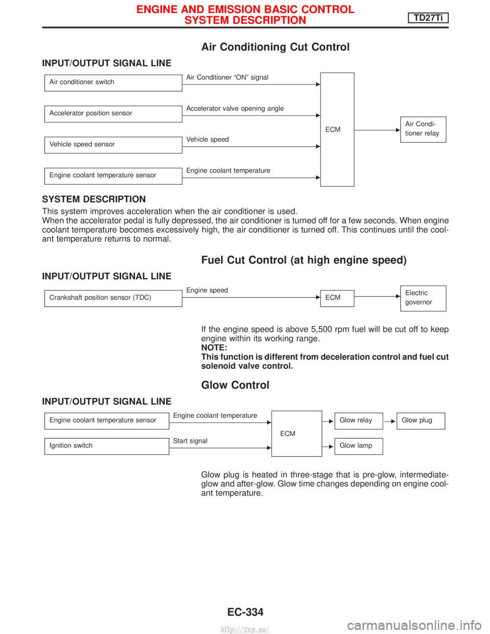
Air Conditioning Cut Control
INPUT/OUTPUT SIGNAL LINE
Air conditioner switchEAir Conditioner ªONº signalECM
EAir Condi-
tioner relay
Accelerator position sensorEAccelerator valve opening angle
Vehicle speed sensor
EVehicle speed
Engine coolant temperature sensor
EEngine coolant temperature
SYSTEM DESCRIPTION
This system improves acceleration when the air conditioner is used.
When the accelerator pedal is fully depressed, the air conditioner is turned off for a few seconds. When engine
coolant temperature becomes excessively high, the air conditioner is turned off. This continues until the cool-
ant temperature returns to normal.
Fuel Cut Control (at high engine speed)
INPUT/OUTPUT SIGNAL LINE
Crankshaft position sensor (TDC)EEngine speed ECMEElectric
governor
If the engine speed is above 5,500 rpm fuel will be cut off to keep
engine within its working range.
NOTE:
This function is different from deceleration control and fuel cut
solenoid valve control.
Glow Control
INPUT/OUTPUT SIGNAL LINE
Engine coolant temperature sensorEEngine coolant temperature
ECMEGlow relayEGlow plug
Ignition switchEStart signalEGlow lamp
Glow plug is heated in three-stage that is pre-glow, intermediate-
glow and after-glow. Glow time changes depending on engine cool-
ant temperature.
ENGINE AND EMISSION BASIC CONTROLSYSTEM DESCRIPTIONTD27Ti
EC-334
http://vnx.su/
Page 640 of 1833
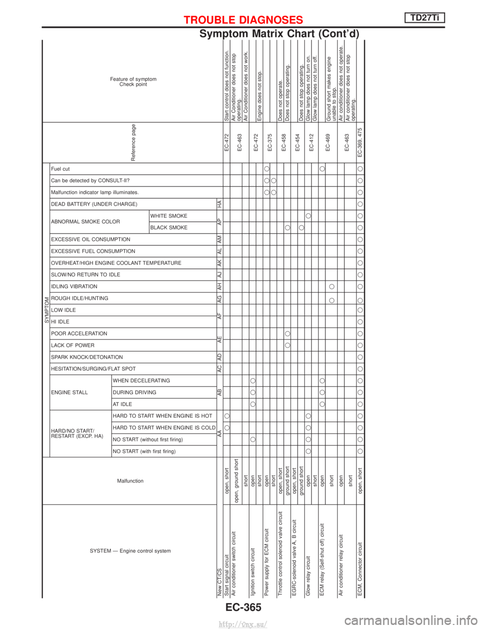
SYSTEM Ð Engine control systemMalfunction
SYMPTOM
Reference page
Feature of symptomCheck point
HARD/NO START/
RESTART (EXCP. HA) ENGINE STALL HESITATION/SURGING/FLAT SPOT SPARK KNOCK/DETONATION
LACK OF POWER
POOR ACCELERATION
HI IDLE
LOW IDLE
ROUGH IDLE/HUNTING
IDLING VIBRATION
SLOW/NO RETURN TO IDLE
OVERHEAT/HIGH ENGINE COOLANT TEMPERATURE
EXCESSIVE FUEL CONSUMPTION
EXCESSIVE OIL CONSUMPTION ABNORMAL SMOKE COLOR
DEAD BATTERY (UNDER CHARGE) Malfunction indicator lamp illuminates.
Can be detected by CONSULT-II?
Fuel cut NO START (with first firing)
NO START (without first firing)
HARD TO START WHEN ENGINE IS COLD
HARD TO START WHEN ENGINE IS HOT
AT IDLE
DURING DRIVING
WHEN DECELERATINGBLACK SMOKE
WHITE SMOKE
New CT/CS
AAAB AC AD AE AF AG AH AJ AK AL AM AP HA
Start signal circuit open, shortqq EC-472 Start control does not function.
Air conditioner switch circuit open, ground short
EC-463Air Conditioner does not stop
operating.
short Air Conditioner does not work.
Ignition switch circuit open q qqq
EC-472
short Engine does not stop.
Power supply for ECM circuit open qqq
EC-375
short qq
Throttle control solenoid valve circuit open, short EC-458Does not operate.
ground short qq q Does not stop operating.
EGRC-solenoid valve A, B circuit open, short EC-454
ground short qDoes not stop operating.
Glow relay circuit open qqqq q
EC-412Glow lamp does not turn on.
short Glow lamp does not turn off.
ECM relay (Self-shut off) circuit open qqq q
EC-469
short qqGround short makes engine
unable to stop.
Air conditioner relay circuit open EC-463Air conditioner does not operate.
short Air conditioner does not stop
operating.
ECM, Connector circuit open, short qqqqqqqqqqqqqq qqqqqqqqqqq EC-369, 475
TROUBLE DIAGNOSESTD27Ti
Symptom Matrix Chart (Cont'd)
EC-365
http://vnx.su/