2004 NISSAN TERRANO turn signal
[x] Cancel search: turn signalPage 667 of 1833
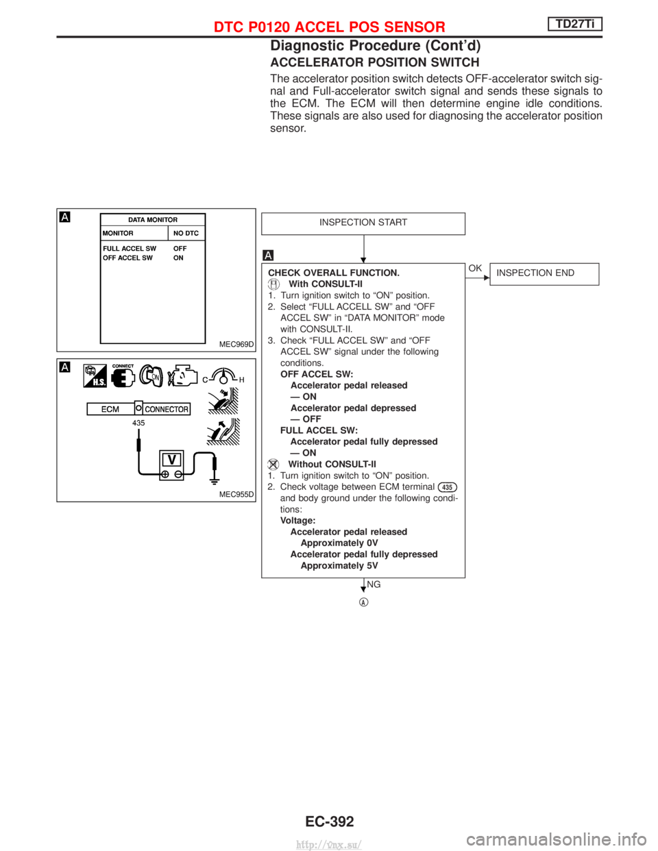
ACCELERATOR POSITION SWITCH
The accelerator position switch detects OFF-accelerator switch sig-
nal and Full-accelerator switch signal and sends these signals to
the ECM. The ECM will then determine engine idle conditions.
These signals are also used for diagnosing the accelerator position
sensor.
INSPECTION START
CHECK OVERALL FUNCTION.
With CONSULT-II
1. Turn ignition switch to ªONº position.
2. Select ªFULL ACCELL SWº and ªOFF ACCEL SWº in ªDATA MONITORº mode
with CONSULT-II.
3. Check ªFULL ACCEL SWº and ªOFF ACCEL SWº signal under the following
conditions.
OFF ACCEL SW:Accelerator pedal released
ÐON
Accelerator pedal depressed
Ð OFF
FULL ACCEL SW: Accelerator pedal fully depressed
ÐON
Without CONSULT-II
1. Turn ignition switch to ªONº position. 2. Check voltage between ECM terminal
435
and body ground under the following condi-
tions:
Voltage: Accelerator pedal releasedApproximately 0V
Accelerator pedal fully depressed Approximately 5V
NG
EOK INSPECTION END
qA
MEC969D
MEC955D
H
H
DTC P0120 ACCEL POS SENSORTD27Ti
Diagnostic Procedure (Cont'd)
EC-392
http://vnx.su/
Page 668 of 1833
qA
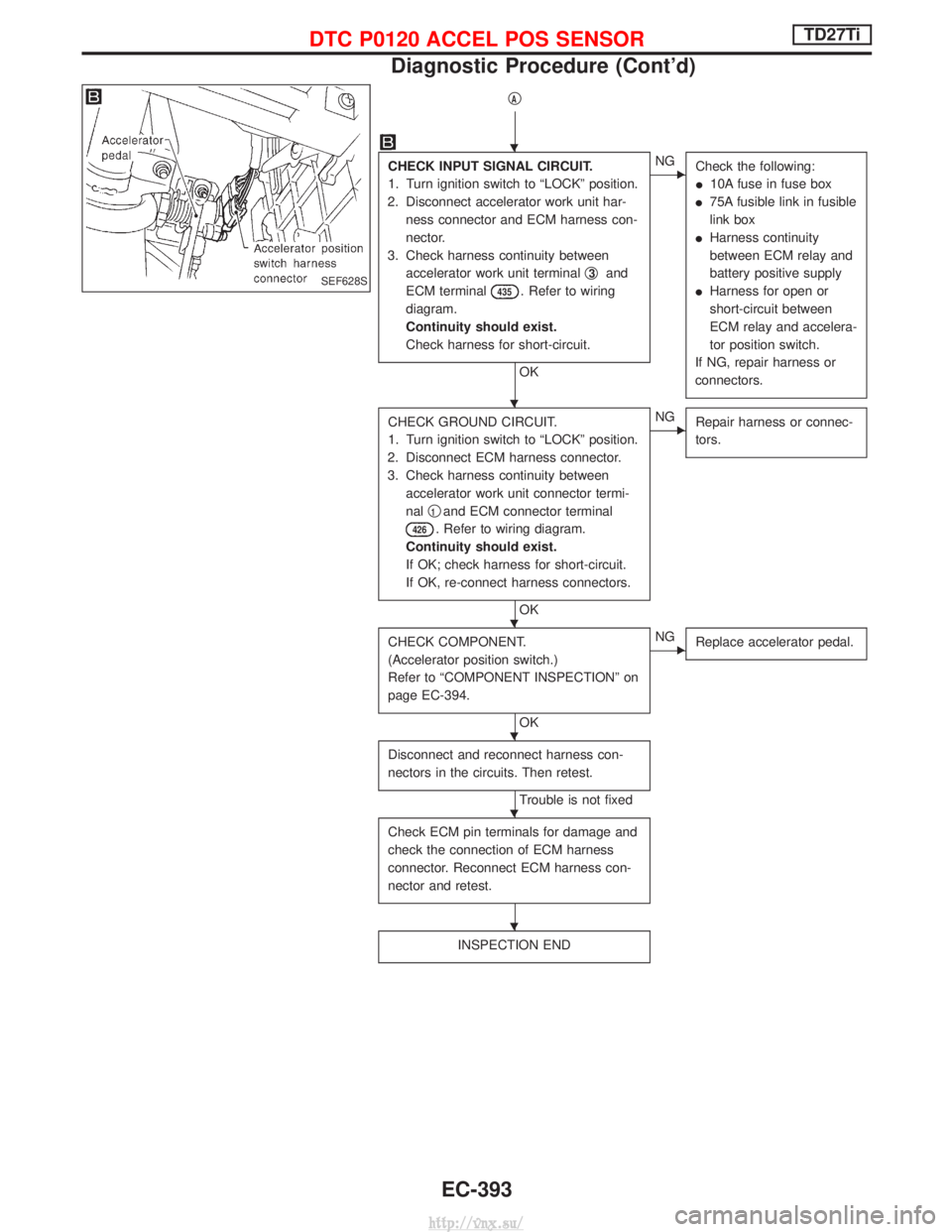
CHECK INPUT SIGNAL CIRCUIT.
1. Turn ignition switch to ªLOCKº position.
2. Disconnect accelerator work unit har- ness connector and ECM harness con-
nector.
3. Check harness continuity between accelerator work unit terminal q
3and
ECM terminal
435. Refer to wiring
diagram.
Continuity should exist.
Check harness for short-circuit.
OK
ENG Check the following:
I10A fuse in fuse box
I 75A fusible link in fusible
link box
I Harness continuity
between ECM relay and
battery positive supply
I Harness for open or
short-circuit between
ECM relay and accelera-
tor position switch.
If NG, repair harness or
connectors.
CHECK GROUND CIRCUIT.
1. Turn ignition switch to ªLOCKº position.
2. Disconnect ECM harness connector.
3. Check harness continuity between accelerator work unit connector termi-
nal q
1and ECM connector terminal
426. Refer to wiring diagram.
Continuity should exist.
If OK; check harness for short-circuit.
If OK, re-connect harness connectors.
OK
ENG Repair harness or connec-
tors.
CHECK COMPONENT.
(Accelerator position switch.)
Refer to ªCOMPONENT INSPECTIONº on
page EC-394.
OK
ENGReplace accelerator pedal.
Disconnect and reconnect harness con-
nectors in the circuits. Then retest.
Trouble is not fixed
Check ECM pin terminals for damage and
check the connection of ECM harness
connector. Reconnect ECM harness con-
nector and retest.
INSPECTION END
SEF628S
H
H
H
H
H
H
DTC P0120 ACCEL POS SENSORTD27Ti
Diagnostic Procedure (Cont'd)
EC-393
http://vnx.su/
Page 670 of 1833
Component Description
FUEL TEMPERATURE SENSOR (FTS)
The fuel temperature sensor is used to detect the fuel temperature
in the injection pump. The sensor modifies a voltage signal from the
ECM. The modified signal returns to the ECM as the fuel tempera-
ture input. The sensor uses a thermistor which is sensitive to the
change in temperature. The electrical resistance of the thermistor
decreases as temperature increases.
The sensor is built into the inside electrical circuit of the injection
pump.
On Board Diagnosis Logic
DTCMalfunction is detected when ... Check Items
(Possible Cause)
P0180
0402 I
An excessively high or low voltage from the sensor is
detected by ECM. I
Harness or connectors
(The sensor circuit is open or short-circuited.)
I Fuel temperature sensor
DTC Confirmation Procedure
WITH CONSULT-II
1) Turn ignition switch to ªONº position.
2) Select ªDATA MONITORº mode with CONSULT-II.
3) Wait at least 5 seconds.
WITHOUT CONSULT-II
1) Turn ignition switch to ªONº position and wait at least 5 sec-
onds.
2) Turn ignition switch to ªLOCKº position, wait at least 5 seconds and then turn to ªONº position.
3) Perform ªDiagnostic Test Mode IIº (Self-diagnostic results).
DTC P0180 FUEL TEMP SENSORTD27Ti
EC-395
http://vnx.su/
Page 676 of 1833

Diagnostic Procedure
INSPECTION START
CHECK POWER SUPPLY.
Check power supply.
CHECK OUTPUT SIGNAL CIRCUIT.
With CONSULT-II
1. Turn ignition switch to ªONº position.
2. Select ªFUEL CUT SOL/Vº in ªACTIVE TESTº mode with CONSULT-II.
3. Touch ªONº and ªOFFº alternately.
4. Check that operating sound is emitted.
Without CONSULT-II
1. Turn ignition switch to ªLOCKº position.
2. Disconnect ECM harness connector and TVC and shut-off harness connec-
tor.
3. Check harness continuity between TVC and shut-off harness connector termi-
nal q
8and ECM connector terminals
202, TVC and shut-off terminal q10
and ECM terminal349. Refer to wir-
ing diagram.
Continuity should exist.
If OK, check harness for short-circuit.
OK
ENG Repair harness or connec-
tors.
CHECK COMPONENT
[TVC and shut-off (Fuel cut solenoid
valve)].
Refer to ªCOMPONENT INSPECTIONº on
page EC-402.
OK
ENGReplace [TVC and shut-off
(fuel cut solenoid valve)].
Disconnect and reconnect harness con-
nectors in the circuit. Then retest.
Trouble is not fixed.
Check ECM pin terminals for damage and
check the connection of ECM harness
connector. Reconnect ECM harness con-
nector and retest.
INSPECTION END
YEC256A
H
H
H
H
H
H
DTC P0215 FUEL CUT S/V 1TD27Ti
EC-401
http://vnx.su/
Page 678 of 1833

Component Description
INJECTION TIMING CONTROL VALVE
The injection timing control valve is built into the fuel injection
pump. It controls the timer piston to change the fuel injection tim-
ing.
The timing control valve is a solenoid valve located in the line
between high-pressure chamber and low-pressure chamber. It
changes fuel pressure in the high-pressure chamber.
When current flows through the solenoid (the solenoid turns ON),
the timing control valve opens, advancing fuel injection timing.
When current does not flow through it, the timing control valve
closes, retarding injection timing.
The ECM emits an ON-OFF duty signal. The longer the OFF-
duration, the greater the advance angle. The longer the
ON-duration, the greater the retard angle. This means that chang-
ing the ON-OFF duty ratio makes it possible to achieve an optimal
advance angle and accurately control fuel injection timing.
On Board Diagnosis Logic
DTCMalfunction is detected when .... Check Items
(Possible cause)
P0216
0904 I
Injection timing control valve circuit is open or
shorted. I
Harness or connectors
(The injection timing control valve circuit is open or
shorted)
I Injection timing control valve
P1246
0201 I
Injection timing feedback system does not operate
properly. (This system consists essentially of ECM,
injection timing control valve and needle lift sensor.) I
Harness or connectors
[Injection timing control valve, needle lift sensor,
crankshaft position sensor (TDC) circuits]
I Injection timing control valve
I Needle lift sensor
I Crankshaft position sensor (TDC)
I Air in fuel line
DTC P0216 Confirmation Procedure
WITH CONSULT-II
1) Turn ignition switch to ªONº position.
2) Select ªDATA MONITORº mode with CONSULT-II.
3) Wait at least 2 seconds.
WITHOUT CONSULT-II
1) Turn ignition switch to ªONº position.
2) Wait at least 2 seconds.
3) Turn ignition switch to ªLOCKº position, wait at least 5 seconds
and then turn to ªONº position.
4) Perform ªDiagnostic Test Mode IIº (Self-diagnostic results).
SEF638S
DTC P0216 INJ TIMING CONT/V, DTC P1246 F/INJ TIMG F/BTD27Ti
EC-403
http://vnx.su/
Page 681 of 1833
Diagnostic Procedure
INSPECTION START
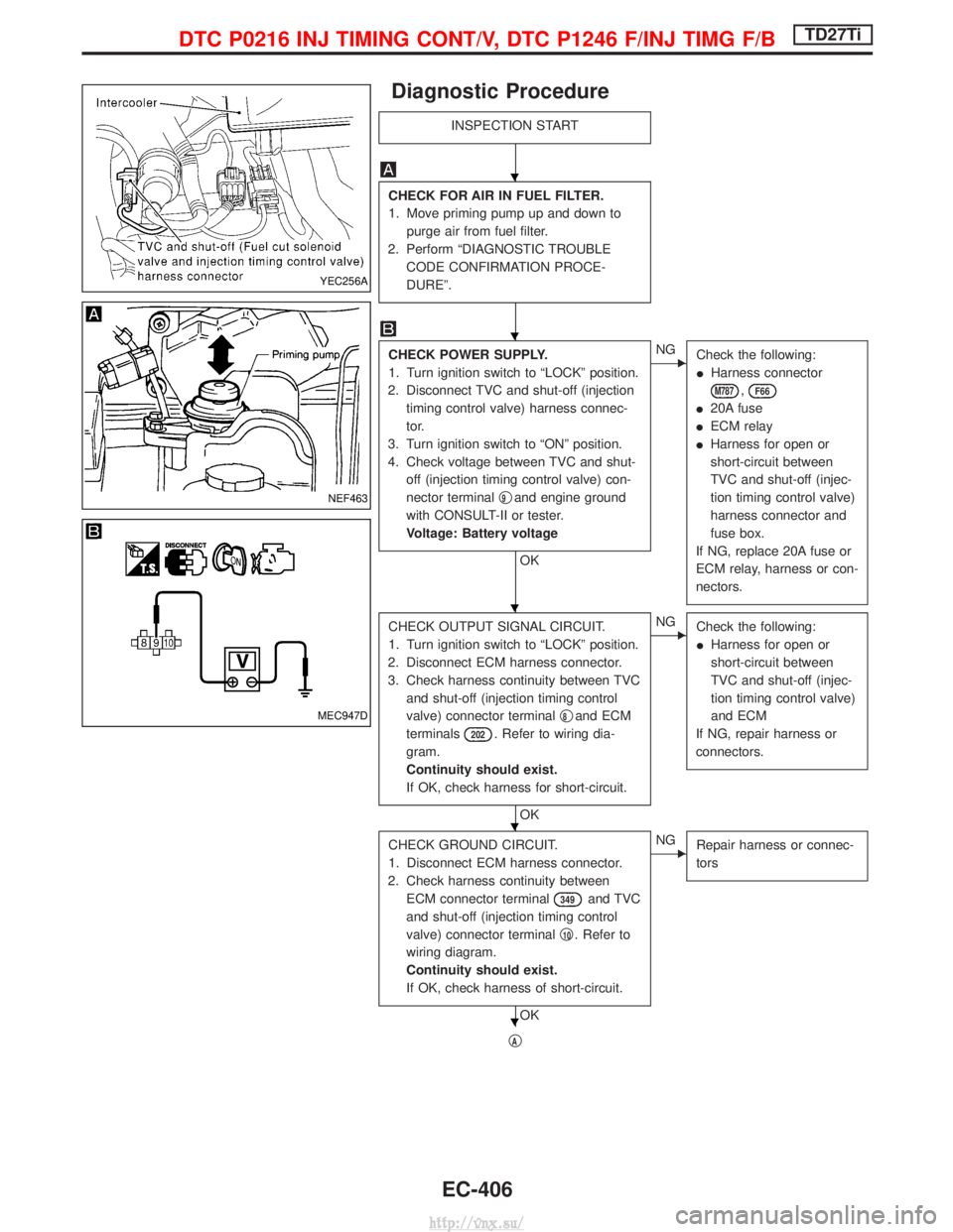
CHECK FOR AIR IN FUEL FILTER.
1. Move priming pump up and down topurge air from fuel filter.
2. Perform ªDIAGNOSTIC TROUBLE CODE CONFIRMATION PROCE-
DUREº.
CHECK POWER SUPPLY.
1. Turn ignition switch to ªLOCKº position.
2. Disconnect TVC and shut-off (injection timing control valve) harness connec-
tor.
3. Turn ignition switch to ªONº position.
4. Check voltage between TVC and shut- off (injection timing control valve) con-
nector terminal q
9and engine ground
with CONSULT-II or tester.
Voltage: Battery voltage
OK
ENG Check the following:
IHarness connector
M787,F66
I20A fuse
I ECM relay
I Harness for open or
short-circuit between
TVC and shut-off (injec-
tion timing control valve)
harness connector and
fuse box.
If NG, replace 20A fuse or
ECM relay, harness or con-
nectors.
CHECK OUTPUT SIGNAL CIRCUIT.
1. Turn ignition switch to ªLOCKº position.
2. Disconnect ECM harness connector.
3. Check harness continuity between TVC and shut-off (injection timing control
valve) connector terminal q
8and ECM
terminals
202. Refer to wiring dia-
gram.
Continuity should exist.
If OK, check harness for short-circuit.
OK
ENG Check the following:
IHarness for open or
short-circuit between
TVC and shut-off (injec-
tion timing control valve)
and ECM
If NG, repair harness or
connectors.
CHECK GROUND CIRCUIT.
1. Disconnect ECM harness connector.
2. Check harness continuity between ECM connector terminal
349and TVC
and shut-off (injection timing control
valve) connector terminal q
10. Refer to
wiring diagram.
Continuity should exist.
If OK, check harness of short-circuit.
OK
ENG Repair harness or connec-
tors
qA
YEC256A
NEF463
MEC947D
H
H
H
H
H
DTC P0216 INJ TIMING CONT/V, DTC P1246 F/INJ TIMG F/BTD27Ti
EC-406
http://vnx.su/
Page 683 of 1833
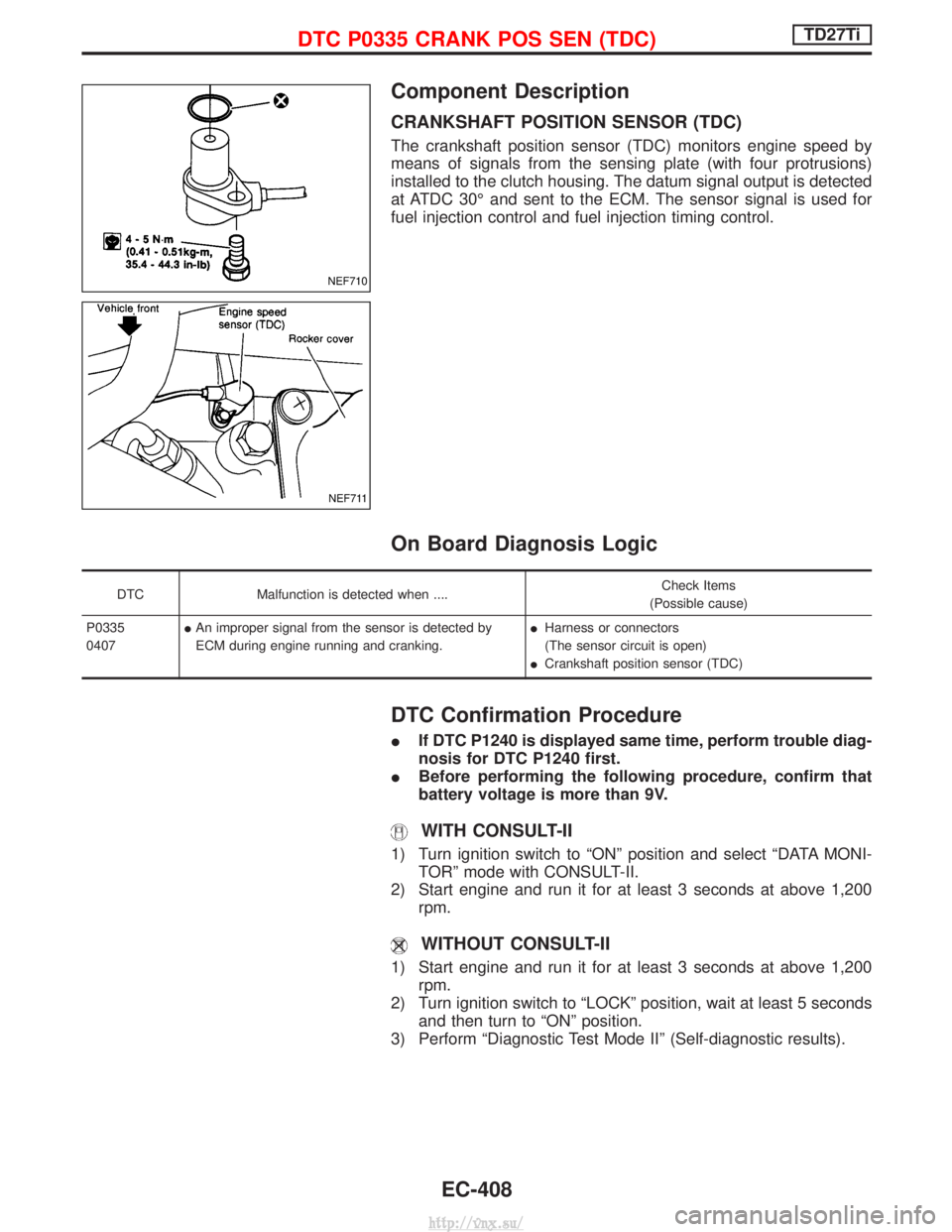
Component Description
CRANKSHAFT POSITION SENSOR (TDC)
The crankshaft position sensor (TDC) monitors engine speed by
means of signals from the sensing plate (with four protrusions)
installed to the clutch housing. The datum signal output is detected
at ATDC 30É and sent to the ECM. The sensor signal is used for
fuel injection control and fuel injection timing control.
On Board Diagnosis Logic
DTCMalfunction is detected when .... Check Items
(Possible cause)
P0335
0407 I
An improper signal from the sensor is detected by
ECM during engine running and cranking. I
Harness or connectors
(The sensor circuit is open)
I Crankshaft position sensor (TDC)
DTC Confirmation Procedure
I If DTC P1240 is displayed same time, perform trouble diag-
nosis for DTC P1240 first.
I Before performing the following procedure, confirm that
battery voltage is more than 9V.
WITH CONSULT-II
1) Turn ignition switch to ªONº position and select ªDATA MONI-
TORº mode with CONSULT-II.
2) Start engine and run it for at least 3 seconds at above 1,200 rpm.
WITHOUT CONSULT-II
1) Start engine and run it for at least 3 seconds at above 1,200rpm.
2) Turn ignition switch to ªLOCKº position, wait at least 5 seconds and then turn to ªONº position.
3) Perform ªDiagnostic Test Mode IIº (Self-diagnostic results).
NEF710
NEF711
DTC P0335 CRANK POS SEN (TDC)TD27Ti
EC-408
http://vnx.su/
Page 685 of 1833

Diagnostic Procedure
INSPECTION START
CHECK INPUT SIGNAL CIRCUIT.
1. Turn ignition switch to ªLOCKº position.
2. Disconnect crankshaft position sensor (TDC) and ECM harness connectors.
3. Check continuity between ECM termi- nal
344and crankshaft position sen-
sor connector terminal q
2. Refer to wir-
ing diagram.
Continuity should exist.
If OK, check harness for short-circuit.
OK
ENG Check the following:
IHarness for open-circuit
between ECM and
crankshaft position sen-
sor (TDC).
If NG, repair harness or
connectors.
CHECK GROUND CIRCUIT-I.
Check harness continuity between crank-
shaft position sensor connector terminal q
1
and ECM terminals331. Refer to wiring
diagram.
Continuity should exist.
If OK, check harness for short-circuit.
OK
ENG Check the following:
IHarness for open-circuit
between crankshaft
position sensor (TDC)
harness connector and
ECM
If NG, repair harness or
connectors.
CHECK GROUND CIRCUIT-II.
Check harness continuity between crank-
shaft position sensor connector terminal q
3
and ECM terminal332. Refer to wiring
diagram.
Continuity should exist.
If OK, check harness for short-circuit.
OK
ENG Check the following:
IHarness for open-circuit
between crankshaft
position sensor (TDC)
and engine ground.
If NG, repair harness or
connectors.
CHECK COMPONENT
[Crankshaft position sensor (TDC)].
Refer to ªCOMPONENT INSPECTIONº,
EC-411.
OK
ENG Replace crankshaft posi-
tion sensor (TDC).
Disconnect and reconnect harness con-
nectors in the circuit. Then retest.
Trouble is not fixed.
Check ECM pin terminals for damage and
check the connection of ECM harness
connector. Reconnect ECM harness con-
nector and retest.
INSPECTION END
NEF712
NEF591
H
H
H
H
H
H
H
DTC P0335 CRANK POS SEN (TDC)TD27Ti
EC-410
http://vnx.su/