Page 436 of 1833

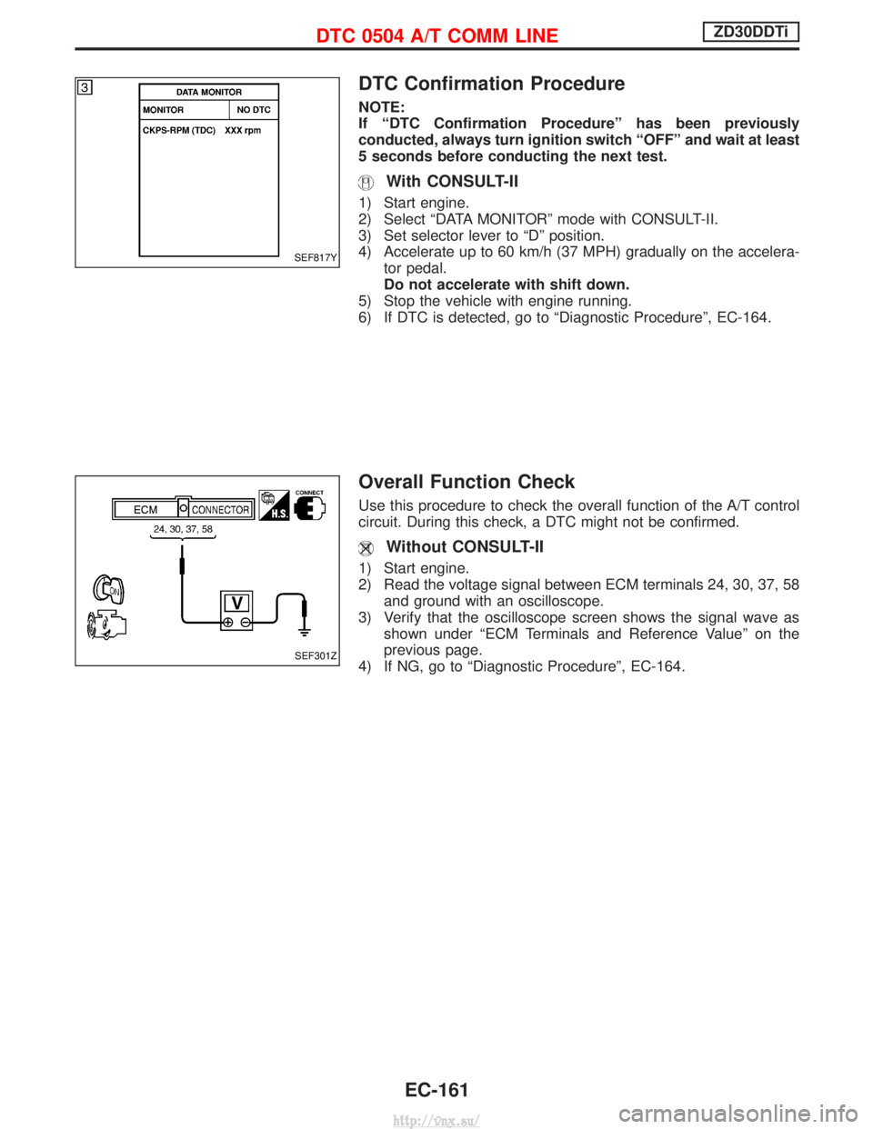
DTC Confirmation Procedure
NOTE:
If ªDTC Confirmation Procedureº has been previously
conducted, always turn ignition switch ªOFFº and wait at least
5 seconds before conducting the next test.
With CONSULT-II
1) Start engine.
2) Select ªDATA MONITORº mode with CONSULT-II.
3) Set selector lever to ªDº position.
4) Accelerate up to 60 km/h (37 MPH) gradually on the accelera-tor pedal.
Do not accelerate with shift down.
5) Stop the vehicle with engine running.
6) If DTC is detected, go to ªDiagnostic Procedureº, EC-164.
Overall Function Check
Use this procedure to check the overall function of the A/T control
circuit. During this check, a DTC might not be confirmed.
Without CONSULT-II
1) Start engine.
2) Read the voltage signal between ECM terminals 24, 30, 37, 58 and ground with an oscilloscope.
3) Verify that the oscilloscope screen shows the signal wave as shown under ªECM Terminals and Reference Valueº on the
previous page.
4) If NG, go to ªDiagnostic Procedureº, EC-164.
SEF817Y
SEF301Z
DTC 0504 A/T COMM LINEZD30DDTi
EC-161
http://vnx.su/
Page 439 of 1833
Diagnostic Procedure
1 CHECK INPUT SIGNAL CIRCUIT
1. Turn ignition switch ªOFFº.
2. Disconnect ECM harness connector and TCM (Transmission control module) harness connector.
MEC020E
MEC026E
3. Check harness continuity between the following terminals. Refer to Wiring Diagram.
MTBL0532
Continuity should exist.OK or NG
OK EGO TO 3.
NG EGO TO 2.
2 DETECT MALFUNCTIONING PART
Check the following.
IHarness connectors M788, F93 (LHD models)
I Harness for open or short between ECM and TCM (Transmission control module)
ERepair harness or connectors.
DTC 0504 A/T COMM LINEZD30DDTi
EC-164
http://vnx.su/
Page 480 of 1833
Description
The ECM consists of a microcomputer and connectors for signal
input and output and for power supply. The unit controls the engine.
On Board Diagnosis Logic
Malfunction is detected when ...Check Items (Possible Cause)
I An excessively high or low voltage from the absolute pressure
sensor (built-into ECM) is sent to ECM. I
ECM
DTC Confirmation Procedure
WITH CONSULT-II
1) Turn ignition switch ªONº.
2) Select ªDATA MONITORº mode with CONSULT-II.
3) Start engine and wait at least 2 seconds.
4) If DTC is detected, go to ªDiagnostic Procedureº, EC-206.
WITHOUT CONSULT-II
1) Turn ignition switch ªONº and wait at least 2 seconds.
2) Start engine and wait at least 2 seconds.
3) Turn ignition switch ªOFFº, wait at least 5 seconds and then turn
ªONº.
4) Perform ªDiagnostic Test Mode II (Self-diagnostic results)º with ECM.
5) If DTC is detected, go to ªDiagnostic Procedureº, EC-206.
SEC220B
SEF817Y
DTC 0802 ECM 10ZD30DDTi
EC-205
http://vnx.su/
Page 482 of 1833
Description
The ECM consists of a microcomputer and connectors for signal
input and output and for power supply. The unit controls the engine.
On Board Diagnosis Logic
Malfunction is detected when ...Check Items (Possible Cause)
I ECM input signal processing function is malfunctioning. IECM
DTC Confirmation Procedure
WITH CONSULT-II
1) Turn ignition switch ªONº.
2) Select ªDATA MONITORº mode with CONSULT-II.
3) Wait at least 1 second.
4) If DTC is detected, go to ªDiagnostic Procedureº, EC-208.
WITHOUT CONSULT-II
1) Turn ignition switch ªONº and wait at least 1 second.
2) Turn ignition switch ªOFFº, wait at least 5 seconds and then turn
ªONº.
3) Perform ªDiagnostic Test Mode II (Self-diagnostic results)º with ECM.
4) If DTC is detected, go to ªDiagnostic Procedureº, EC-208.
SEC220B
SEF817Y
DTC 0804 ECM 11ZD30DDTi
EC-207
http://vnx.su/
Page 484 of 1833

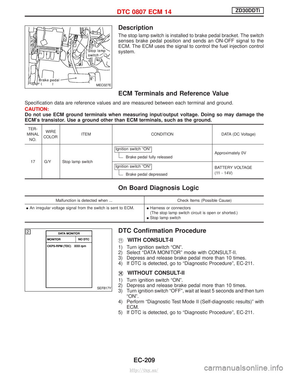
Description
The stop lamp switch is installed to brake pedal bracket. The switch
senses brake pedal position and sends an ON-OFF signal to the
ECM. The ECM uses the signal to control the fuel injection control
system.
ECM Terminals and Reference Value
Specification data are reference values and are measured between each terminal and ground.
CAUTION:
Do not use ECM ground terminals when measuring input/output voltage. Doing so may damage the
ECM's transistor. Use a ground other than ECM terminals, such as the ground.
TER-
MINAL NO. WIRE
COLOR ITEM CONDITION DATA (DC Voltage)
17 G/Y Stop lamp switch Ignition switch ªONº
Brake pedal fully released
Approximately 0V
Ignition switch ªONº
Brake pedal depressed BATTERY VOLTAGE
(11 - 14V)
On Board Diagnosis Logic
Malfunction is detected when ...
Check Items (Possible Cause)
I An irregular voltage signal from the switch is sent to ECM. IHarness or connectors
(The stop lamp switch circuit is open or shorted.)
I Stop lamp switch
DTC Confirmation Procedure
WITH CONSULT-II
1) Turn ignition switch ªONº.
2) Select ªDATA MONITORº mode with CONSULT-II.
3) Depress and release brake pedal more than 10 times.
4) If DTC is detected, go to ªDiagnostic Procedureº, EC-211.
WITHOUT CONSULT-II
1) Turn ignition switch ªONº.
2) Depress and release brake pedal more than 10 times.
3) Turn ignition switch ªOFFº, wait at least 5 seconds and then turn
ªONº.
4) Perform ªDiagnostic Test Mode II (Self-diagnostic results)º with ECM.
5) If DTC is detected, go to ªDiagnostic Procedureº, EC-211.
MEC027E
SEF817Y
DTC 0807 ECM 14ZD30DDTi
EC-209
http://vnx.su/
Page 487 of 1833
3 DETECT MALFUNCTIONING PART
Check the following.
IFuse block (J/B) connector F114 (LHD models), M835 (RHD models)
I 15A fuse
I Harness for open and short between stop lamp switch and fuse
ERepair open circuit or short to ground or short to power in harness or connectors.
4 CHECK STOP LAMP SWITCH INPUT SIGNAL CIRCUIT FOR OPEN AND SHORT
1. Turn ignition switch ªOFFº.
2. Disconnect ECM harness connector.
3. Disconnect stop lamp switch harness connector.
MEC027E
4. Check harness continuity between ECM terminal 17 and stop lamp switch terminal 2. Refer to Wiring Diagram.
Continuity should exist.
5. Also check harness for short to ground and short to power.
OK or NG
OK EGO TO 5.
NG ERepair open circuit or short to ground or short to power in harness or connectors.
DTC 0807 ECM 14ZD30DDTi
Diagnostic Procedure (Cont'd)
EC-212
http://vnx.su/
Page 489 of 1833

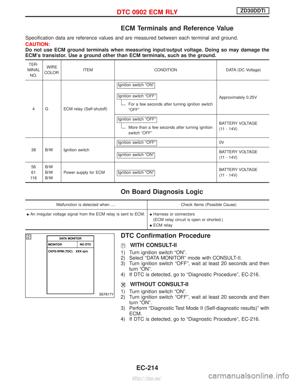
ECM Terminals and Reference Value
Specification data are reference values and are measured between each terminal and ground.
CAUTION:
Do not use ECM ground terminals when measuring input/output voltage. Doing so may damage the
ECM's transistor. Use a ground other than ECM terminals, such as the ground.
TER-
MINAL NO. WIRE
COLOR ITEM CONDITION DATA (DC Voltage)
4 G ECM relay (Self-shutoff) Ignition switch ªONº
Ignition switch ªOFFº
For a few seconds after turning ignition switch
ªOFFº
Approximately 0.25V
Ignition switch ªOFFº
More than a few seconds after turning ignition
switch ªOFFº BATTERY VOLTAGE
(11 - 14V)
38 B/W Ignition switch Ignition switch ªOFFº
0V
Ignition switch ªONº
BATTERY VOLTAGE
(11 - 14V)
56
61
11 6 B/W
B/W
B/W
Power supply for ECM Ignition switch ªONº
BATTERY VOLTAGE
(11 - 14V)
On Board Diagnosis Logic
Malfunction is detected when ....
Check Items (Possible Cause)
I An irregular voltage signal from the ECM relay is sent to ECM. IHarness or connectors
(ECM relay circuit is open or shorted.)
I ECM relay
DTC Confirmation Procedure
WITH CONSULT-II
1) Turn ignition switch ªONº.
2) Select ªDATA MONITORº mode with CONSULT-II.
3) Turn ignition switch ªOFFº, wait at least 20 seconds and then
turn ªONº.
4) If DTC is detected, go to ªDiagnostic Procedureº, EC-216.
WITHOUT CONSULT-II
1) Turn ignition switch ªONº.
2) Turn ignition switch ªOFFº, wait at least 20 seconds and then turn ªONº.
3) Perform ªDiagnostic Test Mode II (Self-diagnostic results)º with ECM.
4) If DTC is detected, go to ªDiagnostic Procedureº, EC-216.SEF817Y
DTC 0902 ECM RLYZD30DDTi
EC-214
http://vnx.su/
Page 491 of 1833
Diagnostic Procedure
1 CHECK ECM POWER SUPPLY CIRCUIT
1. Turn ignition switch ªOFFº.
2. Disconnect ECM relay.
MEC021E
3. Check voltage between ECM relay terminals 2, 3 and ground with CONSULT-II or tester.
MEC978DVoltage: Battery voltageOK or NG
OK EGO TO 3.
NG EGO TO 2.
2 DETECT MALFUNCTIONING PART
Check the following.
I10A fuse
I 15A fuse
I Harness for open and short between ECM relay and battery
ERepair open circuit or short to ground or short to power in harness or connectors.
3 CHECK ECM INPUT SIGNAL CIRCUIT FOR OPEN AND SHORT
1. Turn ignition switch ªOFFº.
2. Disconnect ECM harness connector.
3. Check harness continuity between ECM terminals 56, 61, 116 and ECM relay terminal 5. Refer to Wiring Diagram.
Continuity should exist.
4. Also check harness for short to ground and short to power.
OK or NG
OK EGO TO 5.
NG EGO TO 4.
DTC 0902 ECM RLYZD30DDTi
EC-216
http://vnx.su/