2004 NISSAN TERRANO load capacity
[x] Cancel search: load capacityPage 1109 of 1833

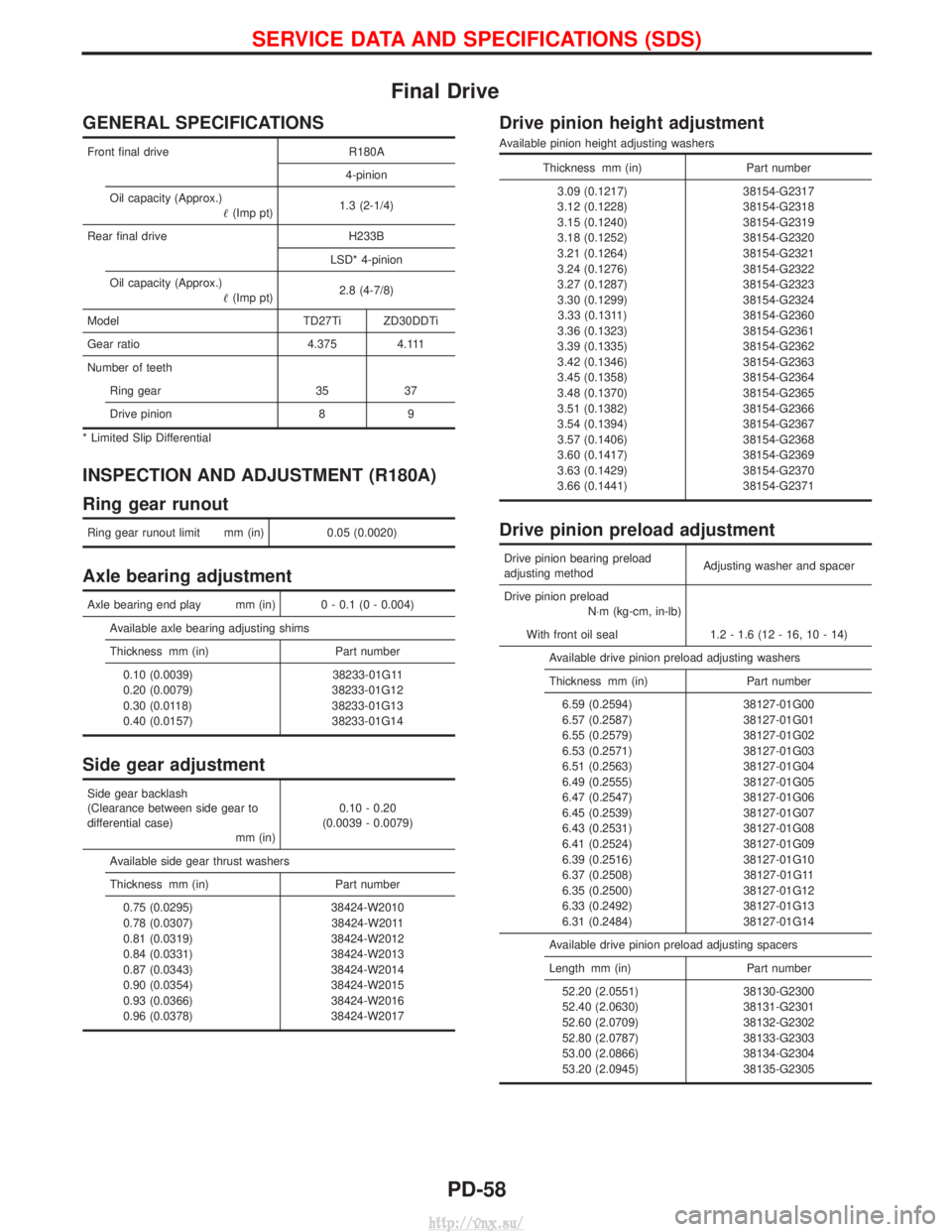
Final Drive
GENERAL SPECIFICATIONS
Front final driveR180A
4-pinion
Oil capacity (Approx.) (Imp pt) 1.3 (2-1/4)
Rear final drive H233B LSD* 4-pinion
Oil capacity (Approx.) (Imp pt) 2.8 (4-7/8)
Model TD27Ti ZD30DDTi
Gear ratio 4.375 4.111
Number of teeth Ring gear 35 37
Drive pinion 8 9
* Limited Slip Differential
INSPECTION AND ADJUSTMENT (R180A)
Ring gear runout
Ring gear runout limit mm (in) 0.05 (0.0020)
Axle bearing adjustment
Axle bearing end play mm (in) 0 - 0.1 (0 - 0.004)
Available axle bearing adjusting shims
Thickness mm (in) Part number0.10 (0.0039) 38233-01G11
0.20 (0.0079) 38233-01G12
0.30 (0.0118) 38233-01G13
0.40 (0.0157) 38233-01G14
Side gear adjustment
Side gear backlash
(Clearance between side gear to
differential case) mm (in)0.10 - 0.20
(0.0039 - 0.0079)
Available side gear thrust washers
Thickness mm (in) Part number 0.75 (0.0295) 38424-W2010
0.78 (0.0307) 38424-W2011
0.81 (0.0319) 38424-W2012
0.84 (0.0331) 38424-W2013
0.87 (0.0343) 38424-W2014
0.90 (0.0354) 38424-W2015
0.93 (0.0366) 38424-W2016
0.96 (0.0378) 38424-W2017
Drive pinion height adjustment
Available pinion height adjusting washers
Thickness mm (in) Part number
3.09 (0.1217) 38154-G2317
3.12 (0.1228) 38154-G2318
3.15 (0.1240) 38154-G2319
3.18 (0.1252) 38154-G2320
3.21 (0.1264) 38154-G2321
3.24 (0.1276) 38154-G2322
3.27 (0.1287) 38154-G2323
3.30 (0.1299) 38154-G2324 3.33 (0.1311) 38154-G2360
3.36 (0.1323) 38154-G2361
3.39 (0.1335) 38154-G2362
3.42 (0.1346) 38154-G2363
3.45 (0.1358) 38154-G2364
3.48 (0.1370) 38154-G2365
3.51 (0.1382) 38154-G2366
3.54 (0.1394) 38154-G2367
3.57 (0.1406) 38154-G2368
3.60 (0.1417) 38154-G2369
3.63 (0.1429) 38154-G2370
3.66 (0.1441) 38154-G2371
Drive pinion preload adjustment
Drive pinion bearing preload
adjusting method Adjusting washer and spacer
Drive pinion preload N×m (kg-cm, in-lb)
With front oil seal 1.2 - 1.6 (12 - 16, 10 - 14) Available drive pinion preload adjusting washers
Thickness mm (in) Part number6.59 (0.2594) 38127-01G00
6.57 (0.2587) 38127-01G01
6.55 (0.2579) 38127-01G02
6.53 (0.2571) 38127-01G03
6.51 (0.2563) 38127-01G04
6.49 (0.2555) 38127-01G05
6.47 (0.2547) 38127-01G06
6.45 (0.2539) 38127-01G07
6.43 (0.2531) 38127-01G08
6.41 (0.2524) 38127-01G09
6.39 (0.2516) 38127-01G10
6.37 (0.2508) 38127-01G11
6.35 (0.2500) 38127-01G12
6.33 (0.2492) 38127-01G13
6.31 (0.2484) 38127-01G14
Available drive pinion preload adjusting spacers
Length mm (in) Part number 52.20 (2.0551) 38130-G2300
52.40 (2.0630) 38131-G2301
52.60 (2.0709) 38132-G2302
52.80 (2.0787) 38133-G2303
53.00 (2.0866) 38134-G2304
53.20 (2.0945) 38135-G2305
SERVICE DATA AND SPECIFICATIONS (SDS)
PD-58
http://vnx.su/
Page 1493 of 1833

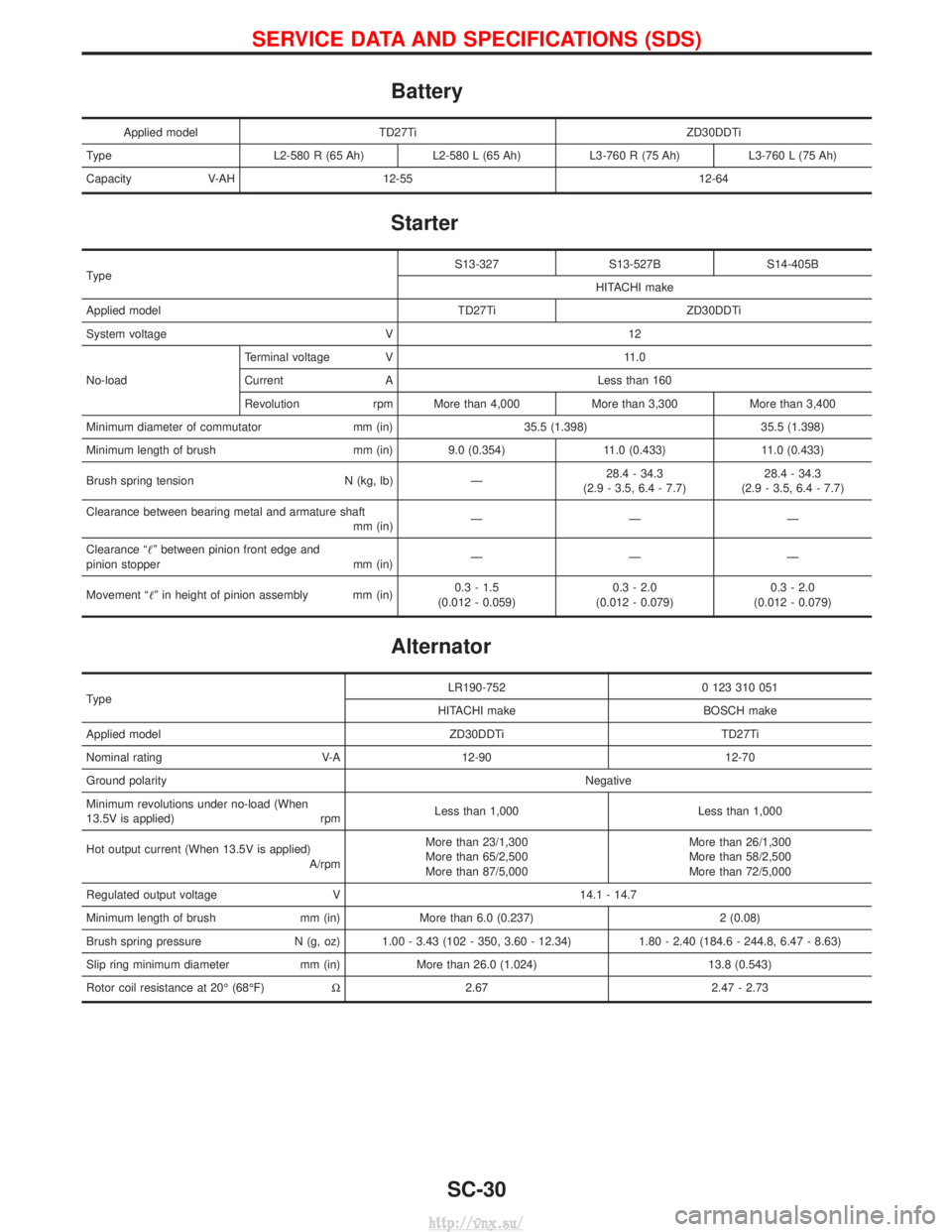
Battery
Applied modelTD27Ti ZD30DDTi
Type L2-580 R (65 Ah)L2-580 L (65 Ah)L3-760 R (75 Ah) L3-760 L (75 Ah)
Capacity V-AH 12-55 12-64
Starter
Type S13-327 S13-527B S14-405B
HITACHI make
Applied model TD27Ti ZD30DDTi
System voltage V 12
No-load Terminal voltage V 11.0
Current A Less than 160
Revolution rpm More than 4,000 More than 3,300 More than 3,400
Minimum diameter of commutator mm (in) 35.5 (1.398) 35.5 (1.398)
Minimum length of brush mm (in) 9.0 (0.354) 11.0 (0.433) 11.0 (0.433)
Brush spring tension N (kg, lb) Ð 28.4 - 34.3
(2.9 - 3.5, 6.4 - 7.7) 28.4 - 34.3
(2.9 - 3.5, 6.4 - 7.7)
Clearance between bearing metal and armature shaft mm (in)ÐÐÐ
Clearance ªº between pinion front edge and
pinion stopper mm (in) ÐÐÐ
Movement ªº in height of pinion assembly mm (in) 0.3 - 1.5
(0.012 - 0.059) 0.3 - 2.0
(0.012 - 0.079) 0.3 - 2.0
(0.012 - 0.079)
Alternator
Type LR190-752 0 123 310 051
HITACHI make BOSCH make
Applied model ZD30DDTi TD27Ti
Nominal rating V-A 12-90 12-70
Ground polarity Negative
Minimum revolutions under no-load (When
13.5V is applied) rpm Less than 1,000 Less than 1,000
Hot output current (When 13.5V is applied) A/rpmMore than 23/1,300
More than 65/2,500
More than 87/5,000 More than 26/1,300
More than 58/2,500
More than 72/5,000
Regulated output voltage V 14.1 - 14.7
Minimum length of brush mm (in) More than 6.0 (0.237) 2 (0.08)
Brush spring pressure N (g, oz) 1.00 - 3.43 (102 - 350, 3.60 - 12.34) 1.80 - 2.40 (184.6 - 244.8, 6.47 - 8.63)
Slip ring minimum diameter mm (in) More than 26.0 (1.024) 13.8 (0.543)
Rotor coil resistance at 20É (68ÉF) W2.67 2.47 - 2.73
SERVICE DATA AND SPECIFICATIONS (SDS)
SC-30
http://vnx.su/
Page 1830 of 1833

INT/V - Wiring diagram ................................EC-282
Intake air control valve control solenoidvalve .........................................................EC-281
Intake Air Volume .........................................EC-150
Intake door control linkage adjustment ..........HA-63
Intake manifold...............................................EM-12
Interior .............................................................BT-18
Interior lamp ..............................................EL-67, 74
Interior lamp on-off control..............................EL-73
ISO 15031-2 Terminology................................GI-34
K
Knuckle spindle ...............................................FA-20 L
License lamp ...................................................EL-49
Limited slip diff. adjustment............................PD-45
Limited slip diff. assembly ..............................PD-47
Limited slip diff. disassembly ...................PD-43, 44
Limited slip diff. inspection .............................PD-44
Line pressure solenoid valve ..........................AT-86
Line pressure test (A/T) ..........................AT-30, 201
Liquid gasket application .................................EM-3
Location of electrical units ............EL-275, 276, 278
Lock, door ...........................................BT-10, 12, 14
Low and reverse brake .................................AT-166
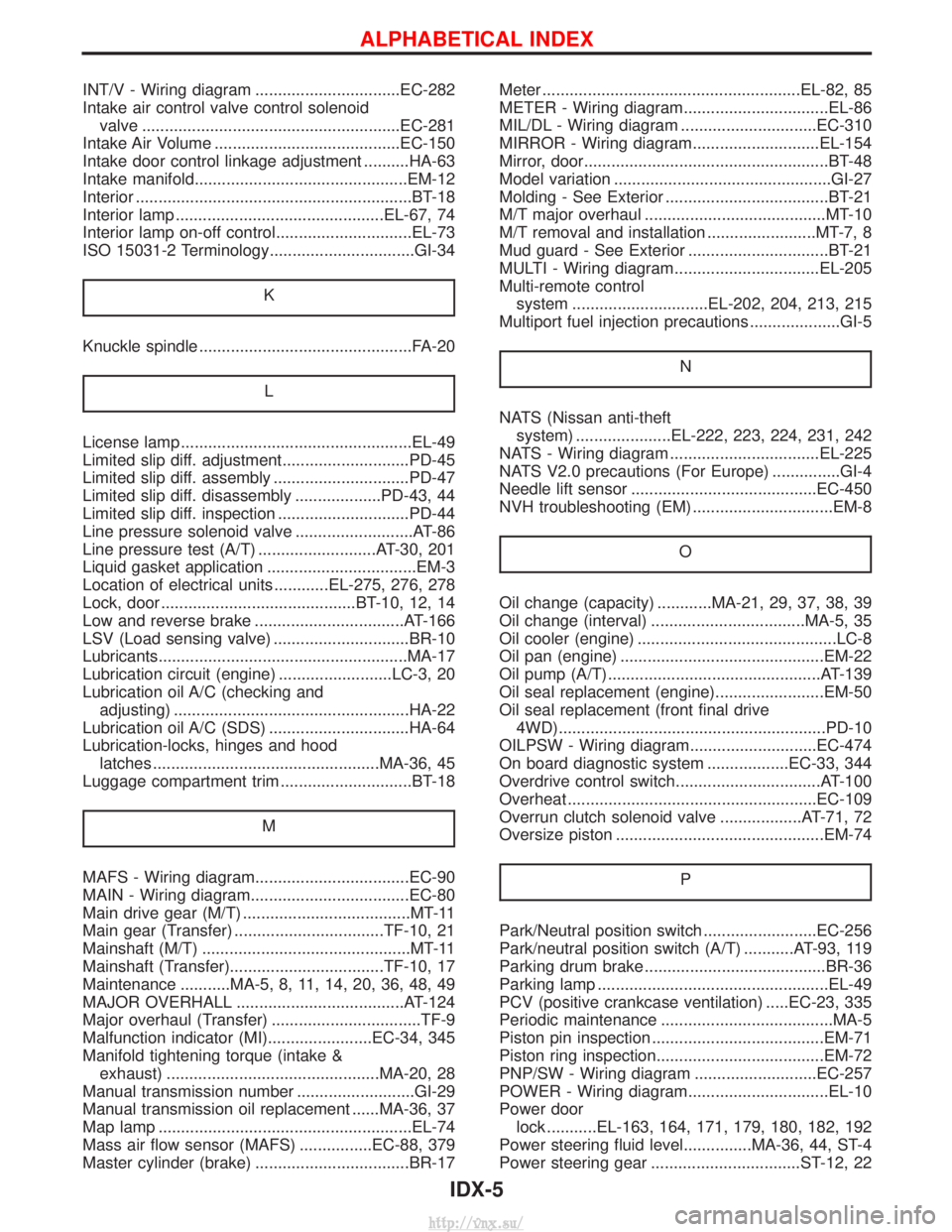
LSV (Load sensing valve) ..............................BR-10
Lubricants.......................................................MA-17
Lubrication circuit (engine) .........................LC-3, 20
Lubrication oil A/C (checking andadjusting) ....................................................HA-22
Lubrication oil A/C (SDS) ...............................HA-64
Lubrication-locks, hinges and hood latches ..................................................MA-36, 45
Luggage compartment trim .............................BT-18
M
MAFS - Wiring diagram..................................EC-90
MAIN - Wiring diagram...................................EC-80
Main drive gear (M/T) .....................................MT-11
Main gear (Transfer) .................................TF-10, 21
Mainshaft (M/T) ..............................................MT-11
Mainshaft (Transfer)..................................TF-10, 17
Maintenance ...........MA-5, 8, 11, 14, 20, 36, 48, 49
MAJOR OVERHALL .....................................AT-124
Major overhaul (Transfer) .................................TF-9
Malfunction indicator (MI).......................EC-34, 345
Manifold tightening torque (intake &exhaust) ...............................................MA-20, 28
Manual transmission number ..........................GI-29
Manual transmission oil replacement ......MA-36, 37
Map lamp ........................................................EL-74
Mass air flow sensor (MAFS) ................EC-88, 379
Master cylinder (brake) ..................................BR-17 Meter .........................................................EL-82, 85
METER - Wiring diagram................................EL-86
MIL/DL - Wiring diagram ..............................EC-310
MIRROR - Wiring diagram............................EL-154
Mirror, door......................................................BT-48
Model variation ................................................GI-27
Molding - See Exterior ....................................BT-21
M/T major overhaul ........................................MT-10
M/T removal and installation ........................MT-7, 8
Mud guard - See Exterior ...............................BT-21
MULTI - Wiring diagram................................EL-205
Multi-remote control
system ..............................EL-202, 204, 213, 215
Multiport fuel injection precautions ....................GI-5
N
NATS (Nissan anti-theftsystem) .....................EL-222, 223, 224, 231, 242
NATS - Wiring diagram .................................EL-225
NATS V2.0 precautions (For Europe) ...............GI-4
Needle lift sensor .........................................EC-450
NVH troubleshooting (EM) ...............................EM-8
O
Oil change (capacity) ............MA-21, 29, 37, 38, 39
Oil change (interval) ..................................MA-5, 35
Oil cooler (engine) ............................................LC-8
Oil pan (engine) .............................................EM-22
Oil pump (A/T)...............................................AT-139
Oil seal replacement (engine)........................EM-50
Oil seal replacement (front final drive4WD)...........................................................PD-10
OILPSW - Wiring diagram............................EC-474
On board diagnostic system ..................EC-33, 344
Overdrive control switch................................AT-100
Overheat .......................................................EC-109
Overrun clutch solenoid valve ..................AT-71, 72
Oversize piston ..............................................EM-74
P
Park/Neutral position switch .........................EC-256
Park/neutral position switch (A/T) ...........AT-93, 119
Parking drum brake ........................................BR-36
Parking lamp ...................................................EL-49
PCV (positive crankcase ventilation) .....EC-23, 335
Periodic maintenance ......................................MA-5
Piston pin inspection ......................................EM-71
Piston ring inspection.....................................EM-72
PNP/SW - Wiring diagram ...........................EC-257
POWER - Wiring diagram...............................EL-10
Power doorlock ...........EL-163, 164, 171, 179, 180, 182, 192
Power steering fluid level...............MA-36, 44, ST-4
Power steering gear .................................ST-12, 22
ALPHABETICAL INDEX
IDX-5
http://vnx.su/