Page 997 of 1833
d. Install band servo retainer onto transmission case.
4. Install rear side clutch and gear components.
a. Place transmission case in vertical position.
b. Slightly lift forward clutch drum assembly. Then slowly rotate itclockwise until its hub passes fully over clutch inner race inside
transmission case.
c. Check to be sure that rotation direction of forward clutch assembly is correct.
d. Install thrust washer onto front of overrun clutch hub.
I Apply petroleum jelly to the thrust washer.
I Insert pawls of thrust washer securely into holes in over-
run clutch hub.
SAT940A
NAT303
SAT944A
SAT945A
SAT946A
ASSEMBLY
Assembly (1) (Cont'd)
AT-184
http://vnx.su/
Page 999 of 1833
j. Install needle bearing onto rear internal gear.
IApply petroleum jelly to needle bearing.
k. Install bearing race onto rear of front internal gear.
I Apply petroleum jelly to bearing race.
I Securely engage pawls of bearing race with holes in front
internal gear.
l. Install front internal gear on transmission case.
5. Install output shaft and parking gear.
a. Insert output shaft from rear of transmission case while slightly lifting front internal gear.
I Do not force output shaft against front of transmission
case.
b. Carefully push output shaft against front of transmission case. Install snap ring on front of output shaft.
I Check to be sure output shaft cannot be removed in rear
direction.
SAT952A
SAT953A
SAT954A
SAT216B
SAT957A
ASSEMBLY
Assembly (1) (Cont'd)
AT-186
http://vnx.su/
Page 1032 of 1833
d. Remove 2-4 shift rod.
e. Remove L & H shift rod and fork assembly with coupling sleeve.
f. Remove needle bearing from main gear.
g. Remove bolts securing front case cover and then remove case.
h. Remove counter gear by tapping lightly.
SMT283A
SMT284A
SMT286A
SMT287A
SMT759A
DISASSEMBLY
TF-15
http://vnx.su/
Page 1033 of 1833
i. Remove main gear by tapping lightly.
SMT288A
DISASSEMBLY
TF-16
http://vnx.su/
Page 1043 of 1833
1. Assemble front case.
a. Install main gear assembly by tapping lightly.
b. Apply sealant to the mating surface and bolts of front casecover and install it on front case.
I These ten bolts should be coated with sealant.
Tightening torque
q
A: 20-23N ×m
(2.1 - 2.3 kg-m, 15 - 16 ft-lb)
q
B: 24-28N ×m
(2.5 - 2.8 kg-m, 18 - 20 ft-lb)
c. Apply gear oil to needle bearing and install it into main gear.
d. Install counter gear assembly by tapping lightly.
e. Install cross shaft and inner shift lever.
When replacing cross shaft, outer shift lever of lock pin of
outer shift lever, replace them as a set.
SMT323A
YMT027
SMT326A
SMT327A
SMT798A
ASSEMBLY
TF-26
http://vnx.su/
Page 1045 of 1833

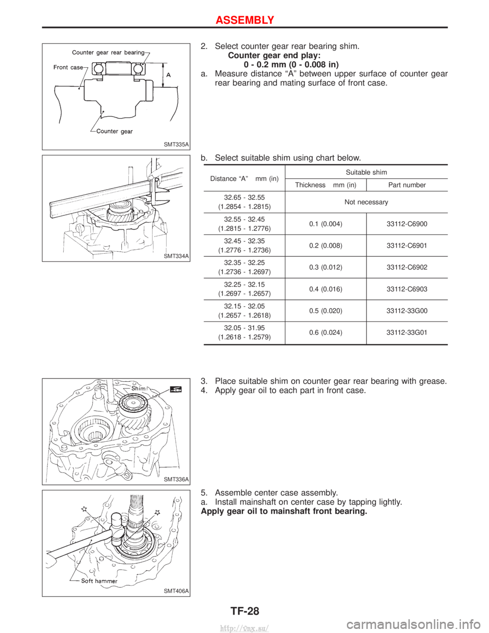
2. Select counter gear rear bearing shim.Counter gear end play:0 - 0.2 mm (0 - 0.008 in)
a. Measure distance ªAº between upper surface of counter gear rear bearing and mating surface of front case.
b. Select suitable shim using chart below.
Distance ªAº mm (in) Suitable shim
Thickness mm (in) Part number
32.65 - 32.55
(1.2854 - 1.2815) Not necessary
32.55 - 32.45
(1.2815 - 1.2776) 0.1 (0.004) 33112-C6900
32.45 - 32.35
(1.2776 - 1.2736) 0.2 (0.008) 33112-C6901
32.35 - 32.25
(1.2736 - 1.2697) 0.3 (0.012) 33112-C6902
32.25 - 32.15
(1.2697 - 1.2657) 0.4 (0.016) 33112-C6903
32.15 - 32.05
(1.2657 - 1.2618) 0.5 (0.020) 33112-33G00
32.05 - 31.95
(1.2618 - 1.2579) 0.6 (0.024) 33112-33G01
3. Place suitable shim on counter gear rear bearing with grease.
4. Apply gear oil to each part in front case.
5. Assemble center case assembly.
a. Install mainshaft on center case by tapping lightly.
Apply gear oil to mainshaft front bearing.
SMT335A
SMT334A
SMT336A
SMT406A
ASSEMBLY
TF-28
http://vnx.su/
Page 1046 of 1833
b. Install bearing retainer.
c. Put drive chain onto the front drive sprocket and front driveshaft, and then put them in center case.
d. Install front drive shaft by tapping lightly.
e. Apply gear oil to needle bearings and install them into front drive sprocket.
These needle bearings will be installed more easily if front
drive sprocket is rotated while installing them.
SMT407A
SMT408A
SMT409A
SMT410A
SMT411A
ASSEMBLY
TF-29
http://vnx.su/
Page 1059 of 1833
2. Remove snap ring.
3. Remove pushed out journal bearing by lightly tapping yoke witha hammer, taking care not to damage journal and yoke hole.
4. Remove bearing at opposite side in above operation.
Put marks on disassembled parts so that they can be rein-
stalled in their original positions from which they were
removed.
Assembly
JOURNAL
1. Assemble journal bearing. Apply recommended multi-purpose grease on bearing inner surface.
When assembling, be careful that needle bearing does not fall
down.
2. Select snap rings that will provide specified play in axial direc- tion of journal, and install them. (Refer to PD-57.)
Select snap rings with a difference in thickness at both sides
within 0.06 mm (0.0024 in).
SPD731
SPD732
SPD131
SPD133
SPD134
PROPELLER SHAFT
Disassembly (Cont'd)
PD-8
http://vnx.su/