Page 1080 of 1833
Differential Case
1. Measure clearance between side gear thrust washer and dif-ferential case.Clearance between side gear thrust washer and differ-
ential case (A þ B): 0.10 - 0.20 mm (0.0039 - 0.0079 in)
The clearance can be adjusted with side gear thrust washer.
(Refer to PD-57.)
2. Apply gear oil to gear tooth surfaces and thrust surfaces and check to see the turn properly.
3. Install L.H. and R.H. differential cases.
4. Place differential case on ring gear.
5. Apply locking agent [Locktite (stud lock) or equivalent] to ring gear bolts, and install them.
Tighten bolts in a criss-cross fashion, lightly tapping bolt head
with a hammer.
6. Press-fit side bearing inner cones on differential case with Tool. Tool number:q
AST33230000
q
BST33061000
SPD656
SPD643
SPD746
PD353
ASSEMBLY (R180A)
PD-29
http://vnx.su/
Page 1099 of 1833
6. Install pinion mate gears and pinion shaft to differential case B.
7. Install side gear to pinion mate gears.
8. Install each disc and plate.
Use same procedures as outlined in steps 1. through 4. above.
9. Install differential case A.
Position differential cases A and B by correctly aligning marks
stamped on cases.
10. Tighten differential case bolts.
:64-69N×m (6.5 - 7.0 kg-m, 47 - 51 ft-lb)
11. Place ring gear on differential case and install new lock straps and bolts.
Tighten bolts in a criss-cross fashion, lightly tapping bolt head
with a hammer.
Then bend up lock straps to lock the bolts in place.
12. Install side bearing inner cone.
13. Check differential torque.
SPD426
SPD429
SPD430
SPD288
LIMITED SLIP DIFFERENTIAL (C200)
Assembly (Cont'd)
PD-48
http://vnx.su/
Page 1106 of 1833

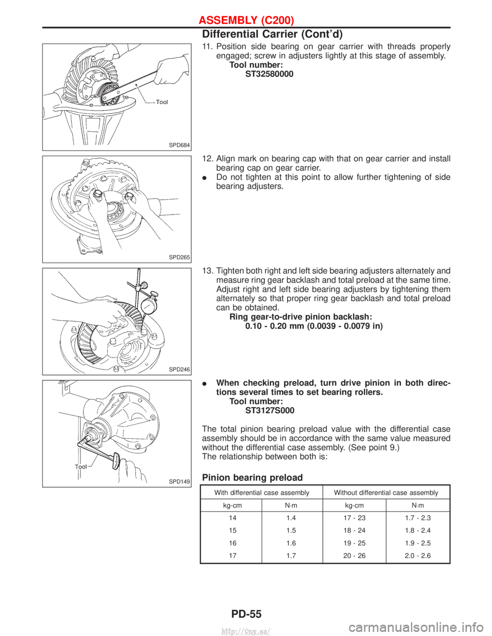
11. Position side bearing on gear carrier with threads properlyengaged; screw in adjusters lightly at this stage of assembly.Tool number: ST32580000
12. Align mark on bearing cap with that on gear carrier and install bearing cap on gear carrier.
I Do not tighten at this point to allow further tightening of side
bearing adjusters.
13. Tighten both right and left side bearing adjusters alternately and measure ring gear backlash and total preload at the same time.
Adjust right and left side bearing adjusters by tightening them
alternately so that proper ring gear backlash and total preload
can be obtained.Ring gear-to-drive pinion backlash: 0.10 - 0.20 mm (0.0039 - 0.0079 in)
I When checking preload, turn drive pinion in both direc-
tions several times to set bearing rollers.
Tool number: ST3127S000
The total pinion bearing preload value with the differential case
assembly should be in accordance with the same value measured
without the differential case assembly. (See point 9.)
The relationship between both is:
Pinion bearing preload
With differential case assembly Without differential case assembly kg-cm N×m kg-cmN×m
14 1.417 - 23 1.7 - 2.3
15 1.518 - 24 1.8 - 2.4
16 1.619 - 25 1.9 - 2.5
17 1.720 - 26 2.0 - 2.6
SPD684
SPD265
SPD246
SPD149
ASSEMBLY (C200)
Differential Carrier (Cont'd)
PD-55
http://vnx.su/
Page 1131 of 1833
Removal
IRemove free-running hub assembly.
Refer to ªFRONT AXLE Ð Auto-lock Free-running Hubº, FA-14.
I Separate drive shaft from knuckle spindle by slightly tapping
drive shaft end.
I Separate tie-rod from knuckle spindle with Tool.
Install stud nut conversely on stud bolt so as not to damage
stud bolt.
I Separate knuckle spindle from ball joints.
(1) Loosen (not remove) upper and lower ball joint tightening nuts.
(2) Separate upper and lower ball joints to knuckle spindle with Tool.
During above operation, never remove ball joint nuts which
are loosened in step (1) above. Tool: HT72520000
NFA008
NFA009
NFA010
SFA927
SFA079
FRONT AXLE Ð Knuckle Spindle
FA-20
http://vnx.su/
Page 1134 of 1833
3. Remove nuts fixing lower ball joint on lower link.
Support lower link with jack.
4. Remove upper ball joint fixing bolt.
5. Remove shock absorber lower bolt.
6. Remove drive shaft with knuckle.
Cover drive shaft boot with a suitable protector.
7. Separate drive shaft from knuckle by slightly tapping it.
SFA843
SFA842
SFA864
SFA878
SFA879
FRONT AXLE Ð Drive Shaft
Removal (Cont'd)FA-23
http://vnx.su/
Page 1135 of 1833
Disassembly
FINAL DRIVE SIDE
Ð TS82F type Ð
1. Remove plug seal from slide joint housing by lightly tappingaround slide joint housing.
2. Remove boot bands.
3. Move boot and slide joint housing toward wheel side, and put matching marks.
4. Pry off snap ring.
5. Detach spider assembly with press.
SFA880
SFA881
SFA963
SFA964
SFA392
FRONT AXLE Ð Drive Shaft
FA-24
http://vnx.su/
Page 1138 of 1833
7. Install new plug seal to slide joint housing by lightly tapping it.
Apply sealant to mating surface of plug seal.
WHEEL SIDE (ZF100)
1. Install new small boot band and boot on drive shaft.
Cover drive shaft serration with tape so as not to damage boot
during installation.
2. Set joint assembly onto drive shaft by lightly tapping it.Install joint assembly securely, ensuring marks which were
made during disassembly are properly aligned.
3. Pack drive shaft with specified amount of grease. Specified amount of grease:100 - 120 g (3.53 - 4.23 oz)
4. Set boot so that is does not swell and deform when its length is ªLº.Length ªLº = 96 - 98 mm (3.78 - 3.86 in)
Make sure that boot is properly installed on the drive shaft
groove.
SFA472
SFA800
SFA884
SFA885
YFA011
FRONT AXLE Ð Drive Shaft
Assembly (Cont'd)
FA-27
http://vnx.su/
Page 1184 of 1833

Removal
CAUTION:
Be careful not to splash brake fluid on painted areas; it may
cause paint damage. If brake fluid is splashed on painted
areas, wash it away with water immediately. DO NOT RUB.
1. Connect a vinyl tube to air bleeder valve.
2. Drain brake fluid from each air bleeder valve, depressing brakepedal to empty fluid from master cylinder.
3. Remove brake pipe flare nuts.
4. Remove master cylinder mounting nuts.
5. Remove protector of master cylinder, and avoid scratching the surface of master cylinder during removal.
CAUTION:
Do not disassemble master cylinder.
NOTE:
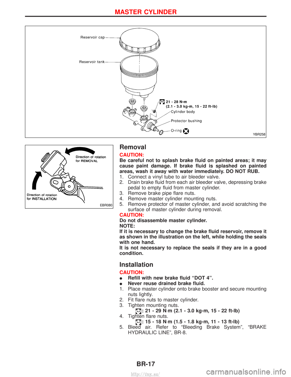
If it is necessary to change the brake fluid reservoir, remove it
as shown in the illustration on the left, while holding the seals
with one hand.
It is not necessary to replace the seals if they are in a good
condition.
Installation
CAUTION:
I Refill with new brake fluid ªDOT 4º.
I Never reuse drained brake fluid.
1. Place master cylinder onto brake booster and secure mounting nuts lightly.
2. Fit flare nuts to master cylinder.
3. Tighten mounting nuts.
:21-29N ×m (2.1 - 3.0 kg-m, 15 - 22 ft-lb)
4. Tighten flare nuts.
:15-18N ×m (1.5 - 1.8 kg-m, 11 - 13 ft-lb)
5. Bleed air. Refer to ªBleeding Brake Systemº, ªBRAKE HYDRAULIC LINEº, BR-8.
YBR258
EBR080
MASTER CYLINDER
BR-17
http://vnx.su/