2004 NISSAN TERRANO remote control
[x] Cancel search: remote controlPage 1261 of 1833
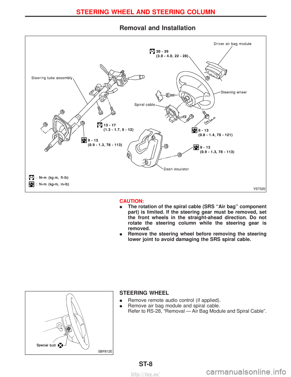
Removal and Installation
CAUTION:
IThe rotation of the spiral cable (SRS ªAir bagº component
part) is limited. If the steering gear must be removed, set
the front wheels in the straight-ahead direction. Do not
rotate the steering column while the steering gear is
removed.
I Remove the steering wheel before removing the steering
lower joint to avoid damaging the SRS spiral cable.
STEERING WHEEL
IRemove remote audio control (if applied).
I Remove air bag module and spiral cable.
Refer to RS-28, ªRemoval Ð Air Bag Module and Spiral Cableº.
YST020
SBF812E
STEERING WHEEL AND STEERING COLUMN
ST-8
http://vnx.su/
Page 1495 of 1833
Oil Pressure Switch Check ...................................... 110
Wiring Diagram - CHIME - ...................................... 111
WIPER AND WASHER ................................................ 112
Wiring Diagram - WIPER - ...................................... 112
Wiring Diagram - WIP/R -........................................ 114
Installation ................................................................ 116
Washer Nozzle Adjustment ..................................... 117
Check Valve ............................................................. 117
Wiring Diagram - HLC - ........................................... 118
HORN, CIGARETTE LIGHTER AND CLOCK ............122
Wiring Diagram - HORN - .......................................122
Wiring Diagram - CIGAR -.......................................123
Wiring Diagram - CLOCK -......................................124
REAR WINDOW DEFOGGER AND DOOR
MIRROR DEFOGGER .................................................125
System Description ..................................................125
Wiring Diagram - DEF - ...........................................126
Trouble Diagnoses...................................................128
Filament Check ........................................................132
Filament Repair .......................................................133
AUDIO ........................................................................\
..134
System Description ..................................................134
Schematic ................................................................136
Wiring Diagram - AUDIO - .......................................138
Wiring Diagram - REMOTE -...................................145
Trouble Diagnoses...................................................147
Inspection.................................................................149
Location of Roof Mounted Antenna .........................150
HEATED SEAT ............................................................151
Wiring Diagram - HSEAT - ......................................151
SUNROOF ....................................................................153
Wiring Diagram - SROOF - .....................................153
DOOR MIRROR ...........................................................154
Wiring Diagram - MIRROR - ...................................154
POWER WINDOW .......................................................156
System Description ..................................................156
Schematic ................................................................158
Wiring Diagram - WINDOW - ..................................159
Trouble Diagnoses...................................................162
POWER DOOR LOCK .................................................163
System Description ..................................................163
Schematic ................................................................164
Wiring Diagram - D/LOCK -.....................................166
Trouble Diagnoses...................................................171
POWER DOOR LOCK - SUPER LOCK - ...................179
Component Parts Location ......................................179
System Description ..................................................180
Schematic ................................................................182 Wiring Diagram - S/LOCK - .....................................184
Trouble Diagnoses...................................................192
MULTI-REMOTE CONTROL SYSTEM .......................202
System Description ..................................................202
Schematic ................................................................204
Wiring Diagram - MULTI - .......................................205
Trouble Diagnoses...................................................213
ID Code Entry Procedure ........................................215
TIME CONTROL UNIT (TCU) .....................................216
System Description ..................................................216
Trouble Diagnosis ....................................................218
Schematic ................................................................220
NATS (Nissan Anti-Theft System) .............................222
System Description ..................................................222
System Composition ................................................223
Component Parts Location ......................................224
Wiring Diagram - NATS -.........................................225
CONSULT-II .............................................................229
Trouble Diagnoses...................................................231
How to Replace NATS IMMU ..................................242
THEFT WARNING SYSTEM .......................................243
Components Parts and Harness Connector
Location ...................................................................243
System Description ..................................................244
Theft Warning System/Schematic ...........................247
Wiring Diagram - THEFT -.......................................248
Trouble Diagnoses...................................................264
LOCATION OF ELECTRICAL UNITS .........................275
Engine Compartment ...............................................275
Passenger Compartment/LHD Models ....................276
Passenger Compartment/RHD Models ...................278
HARNESS LAYOUT ....................................................280
How to Read Harness Layout .................................280
Outline......................................................................281
Main Harness...........................................................282
EFC Harness ...........................................................298
Engine Harness .......................................................310
Body Harness ..........................................................312
Chassis Harness......................................................320
Room Lamp Harness...............................................321
Tailgate Harness ......................................................322
Door Harness (LH side)...........................................323
Door Harness (RH side) ..........................................324
BULB SPECIFICATIONS ............................................325
Headlamps ...............................................................325
Exterior Lamps.........................................................325
Interior Lamps ..........................................................325
WIRING DIAGRAM CODES (CELL CODES) .............326
CONTENTS(Cont'd)
EL-2
http://vnx.su/
Page 1513 of 1833
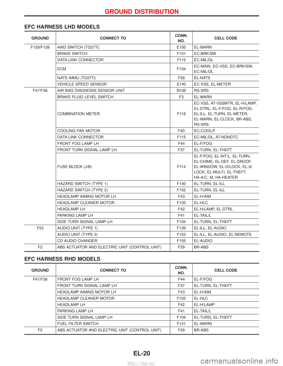
EFC HARNESS LHD MODELS
GROUNDCONNECT TO CONN.
NO. CELL CODE
F129/F128 4WD SWITCH (TD27Ti) E150 EL-WARN
BRAKE SWITCH F101 EC-BRK/SW
DATA LINK CONNECTOR F115 EC-MIL/DL
ECM F134EC-MAIN, EC-VSS, EC-BRK/SW,
EC-MIL/DL
NATS IMMU (TD27Ti) F58 EL-NATS
VEHICLE SPEED SENSOR E140 EC-VSS, EL-METER
F47/F36 AIR BAG DIAGNOSIS SENSOR UNIT B106 RS-SRS
BRAKE FLUID LEVEL SWITCH F3 EL-WARN
COMBINATION METER F118EC-VSS, AT-VSSMTR, EL-H/LAMP,
EL-DTRL, EL-F/FOG, EL-R/FOG,
EL-ILL, EL-TURN, EL-METER,
EL-WARN, EL-CLOCK, BR-ABS,
RS-SRS
COOLING FAN MOTOR F40 EC-COOL/F
DATA LINK CONNECTOR F115 EC-MIL/DL, AT-NONDTC
FRONT FOG LAMP LH F44 EL-F/FOG
FRONT TURN SIGNAL LAMP LH F37 EL-TURN, EL-THEFT
FUSE BLOCK (J/B) F114EL-F/FOG, EL-INT/L, EL-TURN,
EL-CHIME, EL-DEF, EL-SROOF,
EL-WINDOW, EL-D/LOCK, EL-S/
LOCK, EL-MULTI, EL-THEFT,
HA-A/C, M, HA-HEATER
HAZARD SWITCH (TYPE 1) F140 EL-TURN, EL-ILL
HAZARD SWITCH (TYPE 2) F152 EL-TURN, EL-ILL
HEADLAMP AIMING MOTOR LH F43 EL-H/AIM
HEADLAMP CLEANER MOTOR F103 EL-HLC
HEADLAMP LH F42 EL-H/LAMP, EL-DTRL
PARKING LAMP LH F41 EL-TAIL/L
SIDE TURN SIGNAL LAMP LH F104 EL-TURN, EL-THEFT
F53 AUDIO UNIT (TYPE 1) F139 EL-ILL, EL-AUDIO
AUDIO UNIT (TYPE 2) F153 EL-ILL, EL-AUDIO, EL-REMOTE
CD AUDIO CHANGER F155 EL-AUDIO
F2 ABS ACTUATOR AND ELECTRIC UNIT (CONTROL UNIT) F29 BR-ABS
EFC HARNESS RHD MODELS
GROUND CONNECT TO CONN.
NO. CELL CODE
F47/F36 FRONT FOG LAMP LH F44 EL-F/FOG
FRONT TURN SIGNAL LAMP LH F37 EL-TURN, EL-THEFT
HEADLAMP AIMING MOTOR LH F43 EL-H/AIM
HEADLAMP CLEANER MOTOR F103 EL-HLC
HEADLAMP LH F42 EL-H/LAMP
PARKING LAMP LH F41 EL-TAIL/L
SIDE TURN SIGNAL LAMP LH F104 EL-TURN, EL-THEFT
FUEL FILTER SWITCH F141 EL-WARN
F2 ABS ACTUATOR AND ELECTRIC UNIT (CONTROL UNIT) F29 BR-ABS
GROUND DISTRIBUTION
EL-20
http://vnx.su/
Page 1515 of 1833
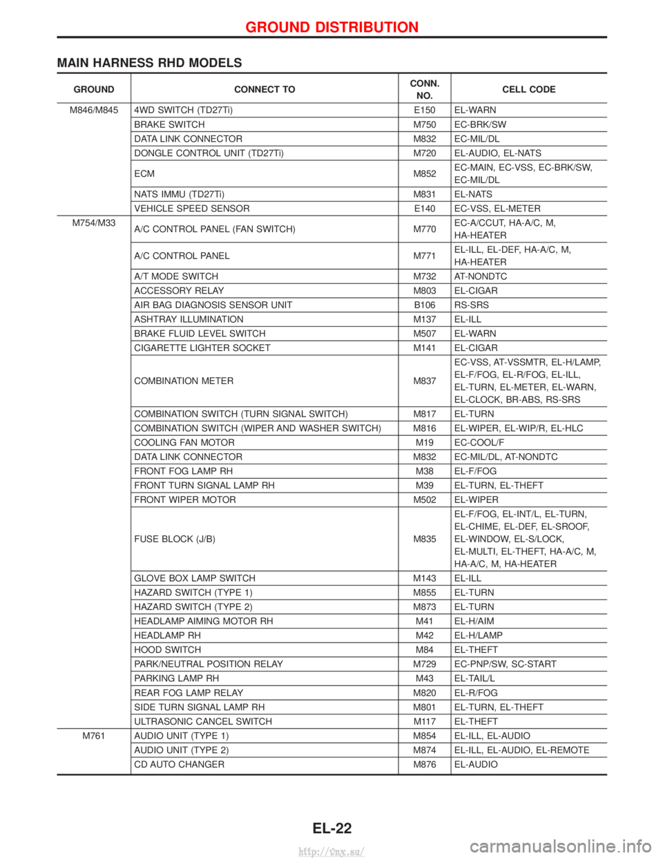
MAIN HARNESS RHD MODELS
GROUNDCONNECT TO CONN.
NO. CELL CODE
M846/M845 4WD SWITCH (TD27Ti) E150 EL-WARN
BRAKE SWITCH M750 EC-BRK/SW
DATA LINK CONNECTOR M832 EC-MIL/DL
DONGLE CONTROL UNIT (TD27Ti) M720 EL-AUDIO, EL-NATS
ECM M852EC-MAIN, EC-VSS, EC-BRK/SW,
EC-MIL/DL
NATS IMMU (TD27Ti) M831 EL-NATS
VEHICLE SPEED SENSOR E140 EC-VSS, EL-METER
M754/M33 A/C CONTROL PANEL (FAN SWITCH) M770EC-A/CCUT, HA-A/C, M,
HA-HEATER
A/C CONTROL PANEL M771EL-ILL, EL-DEF, HA-A/C, M,
HA-HEATER
A/T MODE SWITCH M732 AT-NONDTC
ACCESSORY RELAY M803 EL-CIGAR
AIR BAG DIAGNOSIS SENSOR UNIT B106 RS-SRS
ASHTRAY ILLUMINATION M137 EL-ILL
BRAKE FLUID LEVEL SWITCH M507 EL-WARN
CIGARETTE LIGHTER SOCKET M141 EL-CIGAR
COMBINATION METER M837EC-VSS, AT-VSSMTR, EL-H/LAMP,
EL-F/FOG, EL-R/FOG, EL-ILL,
EL-TURN, EL-METER, EL-WARN,
EL-CLOCK, BR-ABS, RS-SRS
COMBINATION SWITCH (TURN SIGNAL SWITCH) M817 EL-TURN
COMBINATION SWITCH (WIPER AND WASHER SWITCH) M816 EL-WIPER, EL-WIP/R, EL-HLC
COOLING FAN MOTOR M19 EC-COOL/F
DATA LINK CONNECTOR M832 EC-MIL/DL, AT-NONDTC
FRONT FOG LAMP RH M38 EL-F/FOG
FRONT TURN SIGNAL LAMP RH M39 EL-TURN, EL-THEFT
FRONT WIPER MOTOR M502 EL-WIPER
FUSE BLOCK (J/B) M835 EL-F/FOG, EL-INT/L, EL-TURN,
EL-CHIME, EL-DEF, EL-SROOF,
EL-WINDOW, EL-S/LOCK,
EL-MULTI, EL-THEFT, HA-A/C, M,
HA-A/C, M, HA-HEATER
GLOVE BOX LAMP SWITCH M143 EL-ILL
HAZARD SWITCH (TYPE 1) M855 EL-TURN
HAZARD SWITCH (TYPE 2) M873 EL-TURN
HEADLAMP AIMING MOTOR RH M41 EL-H/AIM
HEADLAMP RH M42 EL-H/LAMP
HOOD SWITCH M84 EL-THEFT
PARK/NEUTRAL POSITION RELAY M729 EC-PNP/SW, SC-START
PARKING LAMP RH M43 EL-TAIL/L
REAR FOG LAMP RELAY M820 EL-R/FOG
SIDE TURN SIGNAL LAMP RH M801 EL-TURN, EL-THEFT
ULTRASONIC CANCEL SWITCH M117 EL-THEFT
M761 AUDIO UNIT (TYPE 1) M854 EL-ILL, EL-AUDIO AUDIO UNIT (TYPE 2) M874 EL-ILL, EL-AUDIO, EL-REMOTE
CD AUTO CHANGER M876 EL-AUDIO
GROUND DISTRIBUTION
EL-22
http://vnx.su/
Page 1553 of 1833
or M33, M754 (RHD models).
Ground is supplied to terminal 4 of each rear combination lamp through body grounds B10 and B18.
With power and ground supplied, the time control unit controls the flashing of the hazard warning lamps, and
time control unit supplies power to combination meter terminals 7 or 33, to flash hazard warning indicator.
HAZARD REMINDER OPERATION FOR MULTI-REMOTE CONTROL SYSTEM
When the doors are locked or unlocked by multi-remote controller, time control unit controls turn lamps haz-
ard reminder flashes as follows.
ILocked operation: Flash once
I Unlock operation: Flash twice
EXTERIOR LAMP
System Description (Cont'd)
EL-60
http://vnx.su/
Page 1565 of 1833
![NISSAN TERRANO 2004 Service Repair Manual System Description
POWER SUPPLY AND GROUND
Power is supplied at all times:
Ithrough 15A fuse [No. 5, located in the fuse block (J/B)]
I to time control unit terminal U09,
I through 10A fuse [No. 16, l NISSAN TERRANO 2004 Service Repair Manual System Description
POWER SUPPLY AND GROUND
Power is supplied at all times:
Ithrough 15A fuse [No. 5, located in the fuse block (J/B)]
I to time control unit terminal U09,
I through 10A fuse [No. 16, l](/manual-img/5/57394/w960_57394-1564.png)
System Description
POWER SUPPLY AND GROUND
Power is supplied at all times:
Ithrough 15A fuse [No. 5, located in the fuse block (J/B)]
I to time control unit terminal U09,
I through 10A fuse [No. 16, located in the fuse block (J/B)]
I to front interior lamp terminal 1,
I to rear interior lamp terminal 1 (Wagon models)
I to rear room lamp terminal 2 (Hardtop models)
I to sunroof switch and map lamps terminal 3 (with sunroof),
I to map lamp terminal 2 (without sunroof).
Ground is supplied:
I through body grounds terminals F36, F47 (LHD models) or M33, M754 (RHD models).
I through fuse block terminal MM2
I to time control unit terminal U16
When the driver side door is opened, ground is supplied:
I through driver side door switch case ground and terminal 1, and
I through fuse block terminal B07
I to time control unit terminal U06
When any door is opened, ground is supplied:
I through case ground and terminal 1 of each door switch,
I through fuse block terminal B01
I to time control unit terminal U07.
When the driver side door is unlocked by the door lock/unlock switch, the time control unit receives a ground
signal:
I through body grounds B10 and B18
I to power window main switch terminal 3
I from power window main switch terminal 7
I to time control unit terminal U37.
When a signal, or combination of signals is received by the time control unit, ground is supplied:
I through time control unit terminal U12 and fuse block terminal R01
I to front interior room lamp terminal 2.
I to rear interior lamp terminal 2 (Wagon models).
I to rear interior room lamp terminal 1 (Hardtop models).
With power and ground supplied, the interior room lamps illuminate when the lamp switch is in ªDOORº posi-
tion.
SWITCH OPERATION
When interior room lamp switch is in ªONº position, ground is supplied:
I through front interior lamp case ground.
I through rear interior lamp case ground (Wagon models).
When sunroof switch and map lamps (with sunroof) is ON, ground is supplied:
I through body grounds F36, F47 (LHD models) or M33, M754 (RHD models)
I through fuse block terminal MM2 and R03
I to sunroof switch map lamps terminal 2.
When map lamp (without sunroof) is ON, ground is supplied:
I through body grounds F36, F47 (LHD models) or M33, M754 (RHD models)
I through fuse block terminal MM2 and R03
I to map lamp terminal 1.
With power and ground supplied, the interior room lamps, map lamps illuminate.
INTERIOR ROOM LAMP TIMER OPERATION
When interior room lamp switch is in the ªDOORº position, the time control unit keeps the interior room lamp
illuminated for about 30 seconds when:
I unlock signal is supplied from door lock/unlock switch while all doors are closed
I unlock signal is supplied from remote controller or door key cylinder while all doors are closed
I driver's door is opened and then closed
The timer is canceled when:
I driver's door is locked,
INTERIOR LAMP
EL-72
http://vnx.su/
Page 1656 of 1833
System Description
OPERATION
Power door lock/unlock operation by door key cylinder
IWith the key inserted into front door key cylinder, turning it to LOCK will lock all doors.
I With the key inserted into front door key cylinder, turning it to UNLOCK will unlock all doors.
Power door lock/unlock operation by multi-remote controller
I Pressing multi-remote controller LOCK button will lock all doors.
I Pressing multi-remote controller UNLOCK button once will unlock driver door. Then, if an unlock signal is
sent from the remote controller again within 5 seconds, all other doors will be unlocked.
Power door lock/unlock operation by lock/unlock switch
I With lock/unlock switch on driver door trim setting to LOCK will lock all doors.
I With lock/unlock switch on driver door trim setting to UNLOCK will unlock all doors.
Key reminder system
I If the ignition key is in the ignition key cylinder and driver door is open, setting lock/unlock switch, lock
knob, key or multi-remote controller to ªLOCKº locks the door once but then immediately unlocks all doors.
(signal from door unlock sensor driver side)
POWER DOOR LOCK
EL-163
http://vnx.su/
Page 1695 of 1833
System Description
POWER AND GROUND
Power is supplied at all times
Ito time control unit terminal U09 and
I to door lock switch relay terminal 1
I through 10A fuse [No. 5, located in the fuse block (J/B)], and
I to key switch terminal 2
I through 10A fuse [No. 16, located in the fuse block (J/B)].
When the key switch is ON (ignition key is inserted in key cylinder), power is supplied
I through key switch terminal 1
I to time control unit terminal U22.
When the door switch driver side is ON (door is OPEN), ground is supplied
I to time control unit terminal U06
I through door switch driver side terminal 1 and case ground.
When any of the other door switches is ON (door is OPEN), ground is supplied
I to time control unit terminal U07
I through door switch terminal 1 and case ground.
When lock/unlock switch is LOCK, ground is supplied
I to power window main switch terminal 3
I through body grounds B10 and B18.
Door lock operation signal is supplied
I through power window main switch terminal 14
I to door lock switch relay terminal 2.
With power and ground supplied, door lock switch relay is energized, and the door lock operation signal is
supplied to time control unit terminal U35.
Door unlock operation signal is supplied
I through power window main switch terminal 7
I to time control unit terminal U37.
Remote controller signal is inputted to time control unit (The antenna of the system is combined with time
control unit).
FUNCTION
Multi-remote control system has the following function.
I Door lock (and set super lock)
I Door unlock (and release super lock)
I Hazard reminder
LOCK OPERATION
To lock door by multi-remote controller, the key switch must be at OFF.
When the LOCK signal is input to time control unit (the antenna of the system is combined with time control
unit), time control unit controls to lock doors and set super lock (models with super lock).
UNLOCK OPERATION
Normal Mode
When UNLOCK signal is input to time control unit (the antenna of the system is combined with time control
unit), time control unit controls to unlock doors and release super lock (models with super lock).
Anti Hi-jack Mode
When the UNLOCK signal is input to time control unit (the antenna of the system is combined with time con-
trol unit), time control unit controls to unlock driver's door and release super lock (models with super lock).
Then, if an unlock signal is sent from the remote controller again within 5 seconds, all other doors will be
unlocked.
HAZARD REMINDER
When the doors are locked or unlocked by multi-remote controller, supply power to turn lamps hazard reminder
flashes as follows
ILock operation: Flash once
I Unlock operation: Flash twice
MULTI-REMOTE CONTROL SYSTEM
EL-202
http://vnx.su/