2004 NISSAN TERRANO check transmission fluid
[x] Cancel search: check transmission fluidPage 12 of 1833
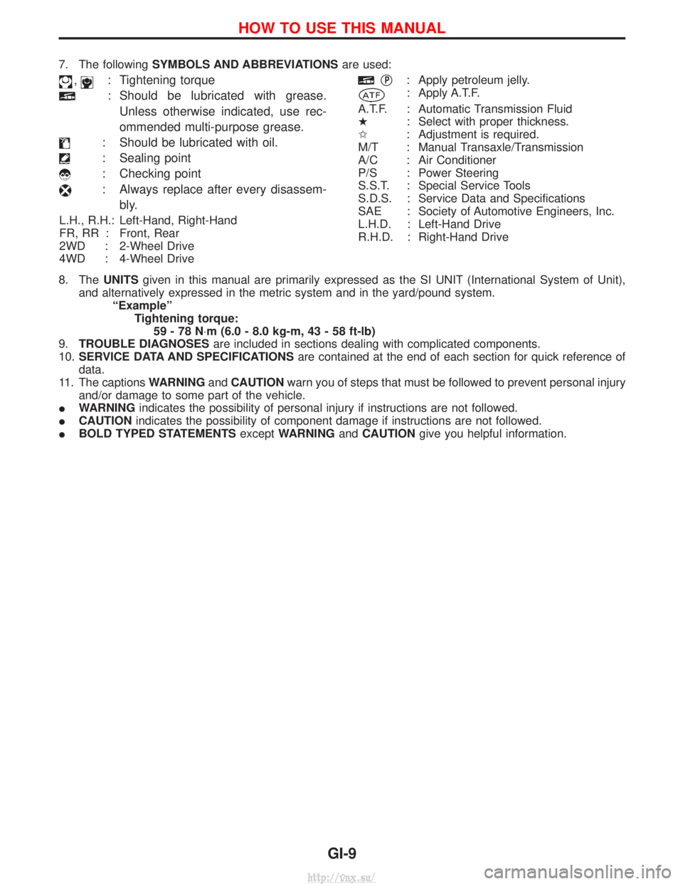
7. The followingSYMBOLS AND ABBREVIATIONS are used:
,: Tightening torque
: Should be lubricated with grease.
Unless otherwise indicated, use rec-
ommended multi-purpose grease.
: Should be lubricated with oil.
: Sealing point
: Checking point
: Always replace after every disassem- bly.
L.H., R.H.: Left-Hand, Right-Hand
FR, RR : Front, Rear
2WD : 2-Wheel Drive
4WD : 4-Wheel Drive
qP: Apply petroleum jelly.
: Apply A.T.F.
A.T.F. : Automatic Transmission Fluid
H : Select with proper thickness.
I : Adjustment is required.
M/T : Manual Transaxle/Transmission
A/C : Air Conditioner
P/S : Power Steering
S.S.T. : Special Service Tools
S.D.S. : Service Data and Specifications
SAE : Society of Automotive Engineers, Inc.
L.H.D. : Left-Hand Drive
R.H.D. : Right-Hand Drive
8. The UNITSgiven in this manual are primarily expressed as the SI UNIT (International System of Unit),
and alternatively expressed in the metric system and in the yard/pound system. ªExampleºTightening torque:59-78N ×m (6.0 - 8.0 kg-m, 43 - 58 ft-lb)
9. TROUBLE DIAGNOSES are included in sections dealing with complicated components.
10. SERVICE DATA AND SPECIFICATIONS are contained at the end of each section for quick reference of
data.
11. The captions WARNINGandCAUTION warn you of steps that must be followed to prevent personal injury
and/or damage to some part of the vehicle.
I WARNING indicates the possibility of personal injury if instructions are not followed.
I CAUTION indicates the possibility of component damage if instructions are not followed.
I BOLD TYPED STATEMENTS exceptWARNING andCAUTION give you helpful information.
HOW TO USE THIS MANUAL
GI-9
http://vnx.su/
Page 44 of 1833
Shown below are Pre-delivery Inspection items required for the new vehicle. It is recommended that
necessary items other than those listed here be added, paying due regard to the conditions in each
country.
Perform applicable items on each model. Consult text of this section for specifications.
UNDER HOOD Ð engine off
lRadiator coolant level and coolant hose connections for leaks
l Battery fluid level, specific gravity and conditions of battery terminals
l Drive belts tension
l Fuel filter for water or dust, and fuel lines and connections for leaks
l Engine oil level and oil leaks
l Brake and clutch reservoirs fluid level and fluid lines for leaks
l Windshield and rear window washer and headlamp cleaner reservoir fluid level
l Power steering reservoir fluid level and hose connections for leaks
ON INSIDE AND OUTSIDE
lRemove front spring/strut spacer (if applicable)
l Operation of all instruments, gauges, lights and accessories
l Operation of horn(s), wiper and washer
l Steering lock for operation
l Check air conditioner for gas leaks
l Front and rear seats, and seat belts for operation
l All moldings, trims and fittings for fit and alignment
l All windows for operation and alignment
l Hood, tailgate, door panels for fit and alignment
l Latches, keys and locks for operation
l Weatherstrips for adhesion and fit
l Headlamp aiming
l Tighten wheel nuts (Inc. inner nuts if applicable)
l Tire pressure (Inc. spare tire)
l Check front wheels for toe-in
l Install clock/voltmeter/room lamp fuse (if applicable)
l Install deodorizing filter to air conditioner (if applicable)
l Remove wiper blade protectors (if applicable)
UNDER BODY
lManual transmission/transaxle, transfer and differential gear oil level
l Brake and fuel lines and oil/fluid reservoirs for leaks
l Tighten bolts and nuts of steering linkage and gear box, suspension, propeller shafts and drive shafts
l Tighten rear body bolts and nuts (Models with wooden bed only)
ROAD TEST
lClutch operation
l Parking brake operation
l Service brake operation
l Automatic transmission/transaxle shift timing and kickdown (if applicable)
l Steering control and returnability
l Engine performance
l Squeaks and rattles
ENGINE OPERATING AND HOT
lAdjust idle speed
l Automatic transmission/transaxle fluid level (if applicable)
l Engine idling and stop knob operation
FINAL INSPECTION
lInstall necessary parts (outside mirror, wheel covers, seat belts, mat, carpet or mud flaps)
l Inspect for interior and exterior metal and paint damage
l Check for spare tire, jack, tools (wheel check) and literature
l Wash, clean interior and exterior
PRE-DELIVERY INSPECTION ITEMS
MA-3
http://vnx.su/
Page 48 of 1833
![NISSAN TERRANO 2004 Service Repair Manual Chassis and Body Maintenance
Abbreviations: R = Replace I = Inspect. Correct or replace if necessary L = Lubricate T = Tighten[ ] = At the specified mileage only
MAINTENANCE OPERATION MAINTENANCE INTE NISSAN TERRANO 2004 Service Repair Manual Chassis and Body Maintenance
Abbreviations: R = Replace I = Inspect. Correct or replace if necessary L = Lubricate T = Tighten[ ] = At the specified mileage only
MAINTENANCE OPERATION MAINTENANCE INTE](/manual-img/5/57394/w960_57394-47.png)
Chassis and Body Maintenance
Abbreviations: R = Replace I = Inspect. Correct or replace if necessary L = Lubricate T = Tighten[ ] = At the specified mileage only
MAINTENANCE OPERATION MAINTENANCE INTERVAL
Refer-ence
page
Perform on a kilometer basis, but on
a semi-annual basis when driving
less than 20,000 km (12,000 miles)
per year. km x 1,000 10 20 30 40 50 60 70 80 90 100 110 120
(miles x 1,000) (6) (12) (18) (24) (30) (36) (42) (48) (54) (60) (66) (72)
Months 6 12 18 24 30 36 42 48 54 50 66 72
Underhood and under vehicle
Headlamp aiming
IIIIII EL-41
Wheel alignment (if necessary, rotate & balance wheels) IIIIII MA-43
Brake pads, discs & other components* IIIIII MA-40
Brake linings, drums & other components* IIIIII MA-41
Foot brake, parking brake & clutch (for free play, stroke &
operation) IIIIII
MA-42
Brake booster vacuum hoses, connections, check valve I I I MA-40
Brake & clutch, systems and fluid (for level and leaks) IIIIII MA-36/
MA-40
Brake fluid* R R R MA-43
Power steering fluid and lines (for level and leaks) IIIIII MA-44
Air bag system See NOTE (1) RS-17
Ventilation air filter* RRRRMA-44
Transfer and standard differential gear oil* I I R I I R MA-37/
MA-38
Manual transmission oil I I I [R] I I MA-36
LSD gear oil (for level and leaks)* I I R I I R MA-38
Steering gear & linkage, axle & suspension parts, propeller
shaft and exhaust system* IIIIII MA-43/
FA-4/
RA-4/
MA-38/ MA-36
Greasing points of steering gear linkage,
propeller shaft and suspension* See NOTE (2)
LLLLLL MA-44/
MA-38
Drive shafts* IIIIIIF A-13
Front wheel bearing grease* IRIRIR MA-39
Free running hub grease* IIIIII MA-40
Body mounting bolts and nuts TTTTTTBT-48
Body corrosion See NOTE (3) MA-47
NOTE: (1) Inspect after 10 years, then every 2 years.
(2) The propeller shaft should be re-greased daily if it is immersed in water.
(3) Inspect once per year.
* Maintenance items with ª*º should be performed more frequently according to ªMaintenance under severe drivingconditionsº.
PERIODIC MAINTENANCE
Maintenance Schedule for Diesel Engine
Models (annual mileage < 30,000 km/year)
(Cont'd)
MA-7
http://vnx.su/
Page 51 of 1833

Chassis and Body Maintenance
Abbreviations: R = Replace I = Inspect. Correct or replace if necessary L = Lubricate T = Tighten
MAINTENANCE OPERATIONMAINTENANCE INTERVAL
Refer-
ence
page
Perform on a kilometer basis only. km x 1,000 10 20 30 40 50 60 70 80 90 100 110 120
(miles x 1,000) (6) (12) (18) (24) (30) (36) (42) (48) (54) (60) (66) (72)
Underhood and under vehicle
Headlamp aiming
IIIIEL-41
Wheel alignment (it necessary, rotate & balance wheels) IIIIMA-43
Brake pads, discs & other components* IIIIMA-40
Brake linings, drums & other components* IIIIMA-41
Foot brake, parking brake & clutch (for free play, stroke &
operation) IIII
MA-42
Brake booster vacuum hoses, connections, check valve I I MA-40
Brake & clutch, systems and fluid (for level and leaks) IIIIMA-36/
MA-40
Brake fluid* R R MA-43
Power steering fluid and lines (for level and leaks) IIIIMA-44
Air bag system See NOTE (1) RS-17
Ventilation air filter* RRRRMA-44
Transfer and standard differential gear oil* IRIRMA-37/
MA-38
Manual transmission oil I I R I MA-36
LSD gear oil* IRIRMA-38
Steering gar & linkage, axle & suspension parts, propeller shaft
and exhaust system* IIIIMA-43/
FA-4/
RA-4/
MA-38/ MA-36
Greasing points of steering gear linkage,
propeller shaft and suspension* See NOTE (2)
LLLL MA-44/
MA-38
Drive shafts* IIIIFA-13
Front wheel bearing grease* IRIRMA-39
Free running hub grease* IIIIMA-40
Body mounting bolts and nuts TTTTBT-48
Body corrosion See NOTE (3) MA-47
NOTE: (1) Inspect after 10 years, then every 2 years.
(2) The propeller shaft should be re-greased daily if it is immersed in water.
(3) Inspect once per year.
* Maintenance items with ª*º should be performed more frequently according to ªMaintenance under severe drivingconditionsº.
PERIODIC MAINTENANCE
Maintenance Schedule for Diesel Engine
Models (annual mileage > 30,000 km/year)
(Cont'd)
MA-10
http://vnx.su/
Page 78 of 1833
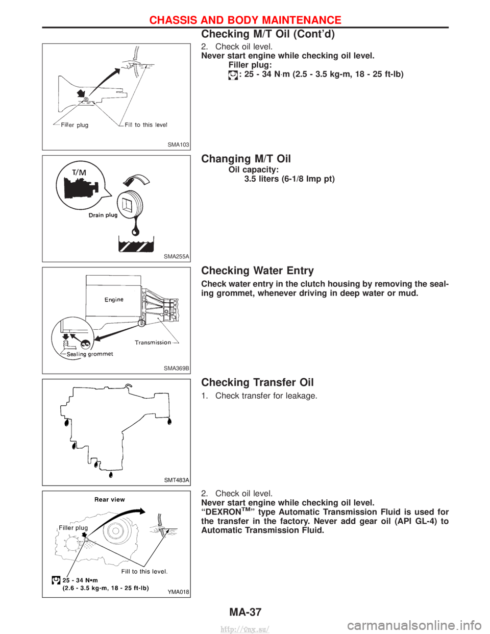
2. Check oil level.
Never start engine while checking oil level.Filler plug:
:25-34N ×m (2.5 - 3.5 kg-m, 18 - 25 ft-lb)
Changing M/T Oil
Oil capacity:
3.5 liters (6-1/8 Imp pt)
Checking Water Entry
Check water entry in the clutch housing by removing the seal-
ing grommet, whenever driving in deep water or mud.
Checking Transfer Oil
1. Check transfer for leakage.
2. Check oil level.
Never start engine while checking oil level.
ªDEXRON
TMº type Automatic Transmission Fluid is used for
the transfer in the factory. Never add gear oil (API GL-4) to
Automatic Transmission Fluid.
SMA103
SMA255A
SMA369B
SMT483A
YMA018
CHASSIS AND BODY MAINTENANCE
Checking M/T Oil (Cont'd)
MA-37
http://vnx.su/
Page 79 of 1833
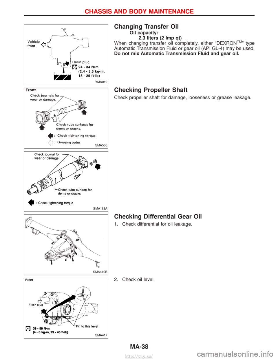
Changing Transfer Oil
Oil capacity:2.3 liters (2 Imp qt)
When changing transfer oil completely, either ªDEXRON
TMº type
Automatic Transmission Fluid or gear oil (API GL-4) may be used.
Do not mix Automatic Transmission Fluid and gear oil.
Checking Propeller Shaft
Check propeller shaft for damage, looseness or grease leakage.
Checking Differential Gear Oil
1. Check differential for oil leakage.
2. Check oil level.
YMA019
SMA566
SMA118A
SMA440B
SMA417
CHASSIS AND BODY MAINTENANCE
MA-38
http://vnx.su/
Page 85 of 1833
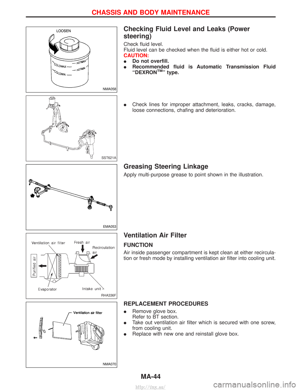
Checking Fluid Level and Leaks (Power
steering)
Check fluid level.
Fluid level can be checked when the fluid is either hot or cold.
CAUTION:
IDo not overfill.
I Recommended fluid is Automatic Transmission Fluid
ªDEXRON
TMº type.
I Check lines for improper attachment, leaks, cracks, damage,
loose connections, chafing and deterioration.
Greasing Steering Linkage
Apply multi-purpose grease to point shown in the illustration.
Ventilation Air Filter
FUNCTION
Air inside passenger compartment is kept clean at either recircula-
tion or fresh mode by installing ventilation air filter into cooling unit.
REPLACEMENT PROCEDURES
IRemove glove box.
Refer to BT section.
I Take out ventilation air filter which is secured with one screw,
from cooling unit.
I Replace with new one and reinstall glove box.
NMA058
SST621A
EMA053
RHA336F
NMA070
CHASSIS AND BODY MAINTENANCE
MA-44
http://vnx.su/
Page 814 of 1833
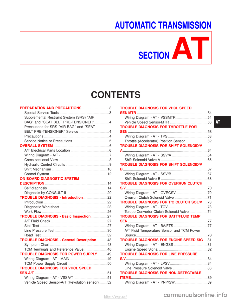
AUTOMATIC TRANSMISSIONSECTION
AT
CONTENTS
PREPARATION AND PRECAUTIONS ............................3
Special Service Tools ..................................................3
Supplemental Restraint System (SRS) ²AIR
BAG² and²SEAT BELT PRE-TENSIONER² ...............4
Precautions for SRS ²AIR BAG² and²SEAT
BELT PRE-TENSIONER² Service ...............................4
Precautions ..................................................................4
Service Notice or Precautions .....................................5
OVERALL SYSTEM ........................................................6
A/T Electrical Parts Location .......................................6
Wiring Diagram - A/T -.................................................7
Cross-sectional View ...................................................8
Hydraulic Control Circuits ............................................9
Shift Mechanism ........................................................10
Control System ..........................................................12
ON BOARD DIAGNOSTIC SYSTEM
DESCRIPTION ...............................................................14
Self-diagnosis ............................................................14
Diagnosis by CONSULT-II .........................................20
TROUBLE DIAGNOSIS - Introduction ........................22
Introduction ................................................................22
Diagnostic Worksheet ................................................23
Work Flow ..................................................................26
TROUBLE DIAGNOSIS - Basic Inspection ................27
A/T Fluid Check .........................................................27
Stall Test ....................................................................27
Line Pressure Test .....................................................30
Road Test...................................................................32
TROUBLE DIAGNOSIS - General Description ...........43
Symptom Chart ..........................................................43
TCM Terminals and Reference Value........................46
TROUBLE DIAGNOSIS FOR POWER SUPPLY ..........49
Wiring Diagram - AT - MAIN ......................................49
TCM Power Supply Circuit ........................................50
TROUBLE DIAGNOSIS FOR VHCL SPEED
SEN×A/T ........................................................................\
.51
Wiring Diagram - AT - VSSA/T ..................................51
Vehicle Speed Sensor×A/T (Revolution sensor) ........52 TROUBLE DIAGNOSIS FOR VHCL SPEED
SEN×MTR
.......................................................................54
Wiring Diagram - AT - VSSMTR ................................54
Vehicle Speed Sensor×MTR ......................................56
TROUBLE DIAGNOSIS FOR THROTTLE POSI
SEN ........................................................................\
........58
Wiring Diagram - AT - TPS ........................................58
Throttle (Accelerator) Position Sensor ......................62
TROUBLE DIAGNOSIS FOR SHIFT SOLENOID/V
A ........................................................................\
.............64
Wiring Diagram - AT - SSV/A ....................................64
Shift Solenoid Valve A ...............................................65
TROUBLE DIAGNOSIS FOR SHIFT SOLENOID/V
B ........................................................................\
.............67
Wiring Diagram - AT - SSV/B ....................................67
Shift Solenoid Valve B ...............................................68
TROUBLE DIAGNOSIS FOR OVERRUN CLUTCH
S/V ........................................................................\
..........70
Wiring Diagram - AT - OVRCSV................................70
Overrun Clutch Solenoid Valve .................................71
TROUBLE DIAGNOSIS FOR T/C CLUTCH SOL/V .....73
Wiring Diagram - AT - TCV........................................73
Torque Converter Clutch Solenoid Valve ..................74
TROUBLE DIAGNOSIS FOR BATT/FLUID TEMP
SEN ........................................................................\
........77
Wiring Diagram - AT - BA/FTS ..................................77
A/T Fluid Temperature Sensor and TCM Power
Source........................................................................\
78
TROUBLE DIAGNOSIS FOR ENGINE SPEED SIG ....81
Wiring Diagram - AT - ENGSS ..................................81
Engine Speed Signal .................................................82
TROUBLE DIAGNOSIS FOR LINE PRESSURE
S/V ........................................................................\
..........84
Wiring Diagram - AT - LPSV......................................84
Line Pressure Solenoid Valve ...................................86
TROUBLE DIAGNOSIS FOR NON-DETECTABLE
ITEMS........................................................................\
.....89 Wiring Diagram - AT - PNP/SW.................................89
http://vnx.su/