2004 NISSAN TERRANO light
[x] Cancel search: lightPage 309 of 1833
IIf the battery is disconnected, the emission-related diagnostic information will be lost after approx.
24 hours.
I Erasing the emission-related diagnostic information using CONSULT-II is easier and quicker than
switching the diagnostic test mode using the data link connector.
NATS (Nissan Anti-Theft System)
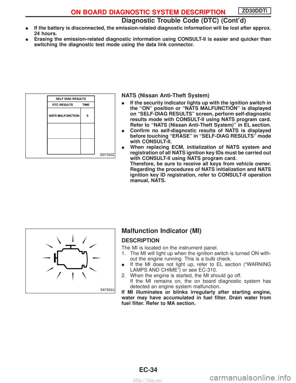
IIf the security indicator lights up with the ignition switch in
the ªONº position or ªNATS MALFUNCTIONº is displayed
on ªSELF-DIAG RESULTSº screen, perform self-diagnostic
results mode with CONSULT-II using NATS program card.
Refer to ªNATS (Nissan Anti-Theft System)º in EL section.
I Confirm no self-diagnostic results of NATS is displayed
before touching ªERASEº in ªSELF-DIAG RESULTSº mode
with CONSULT-II.
I When replacing ECM, initialization of NATS system and
registration of all NATS ignition key IDs must be carried out
with CONSULT-II using NATS program card.
Therefore, be sure to receive all keys from vehicle owner.
Regarding the procedures of NATS initialization and NATS
ignition key ID registration, refer to CONSULT-II operation
manual, NATS.
Malfunction Indicator (MI)
DESCRIPTION
The MI is located on the instrument panel.
1. The MI will light up when the ignition switch is turned ON with-
out the engine running. This is a bulb check.
I If the MI does not light up, refer to EL section (ªWARNING
LAMPS AND CHIMEº) or see EC-310.
2. When the engine is started, the MI should go off. If the MI remains on, the on board diagnostic system has
detected an engine system malfunction.
If MI illuminates or blinks irregularly after starting engine,
water may have accumulated in fuel filter. Drain water from
fuel filter. Refer to MA section.
SEF252Z
SAT652J
ON BOARD DIAGNOSTIC SYSTEM DESCRIPTIONZD30DDTi
Diagnostic Trouble Code (DTC) (Cont'd)
EC-34
http://vnx.su/
Page 310 of 1833
On board diagnostic system function
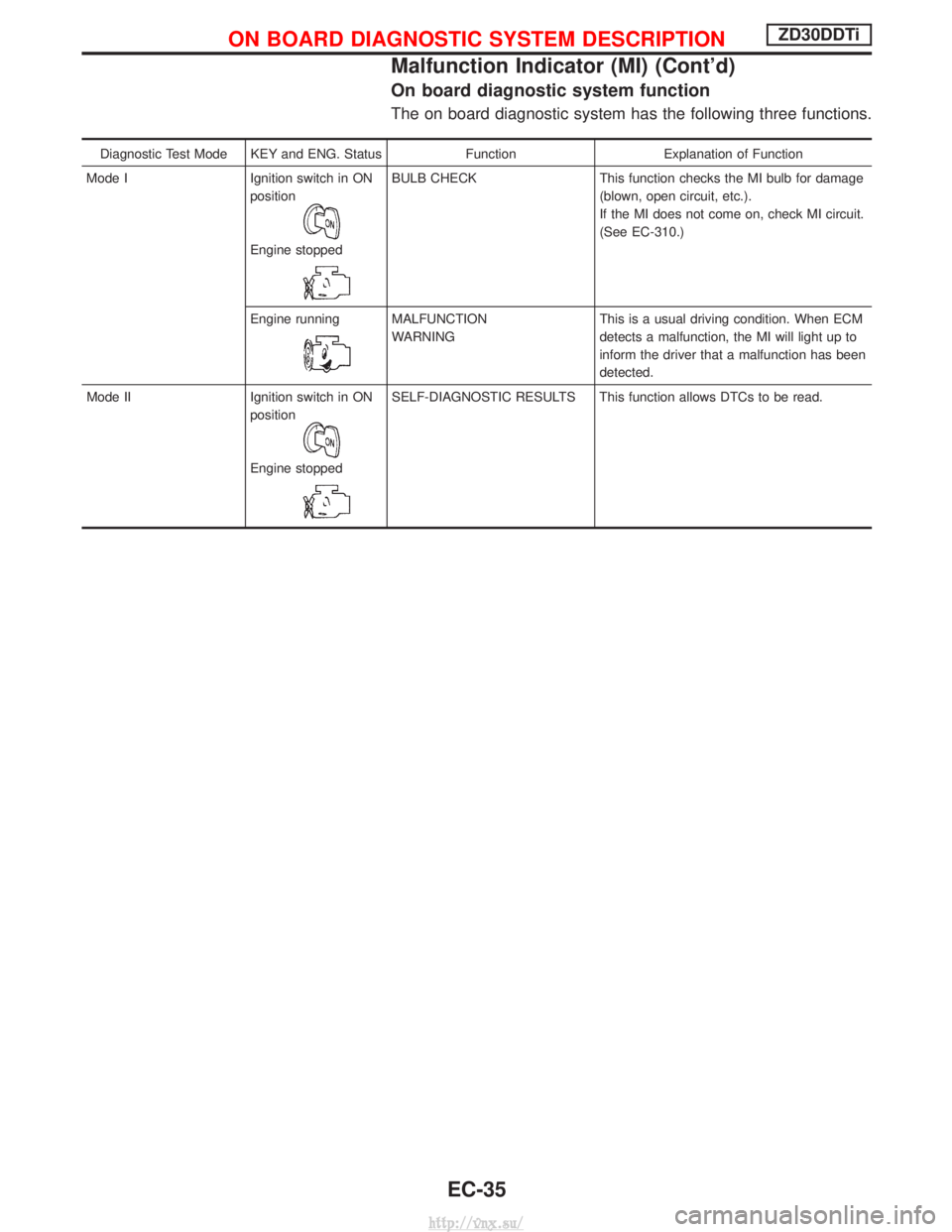
The on board diagnostic system has the following three functions.
Diagnostic Test Mode KEY and ENG. StatusFunctionExplanation of Function
Mode I Ignition switch in ON
position
Engine stopped
BULB CHECK This function checks the MI bulb for damage
(blown, open circuit, etc.).
If the MI does not come on, check MI circuit.
(See EC-310.)
Engine running
MALFUNCTION
WARNING This is a usual driving condition. When ECM
detects a malfunction, the MI will light up to
inform the driver that a malfunction has been
detected.
Mode II Ignition switch in ON position
Engine stopped
SELF-DIAGNOSTIC RESULTS This function allows DTCs to be read.
ON BOARD DIAGNOSTIC SYSTEM DESCRIPTIONZD30DDTi
Malfunction Indicator (MI) (Cont'd)
EC-35
http://vnx.su/
Page 313 of 1833

Relationship between MI, DTC, CONSULT-II and driving patterns
*1: When a malfunction is detected,MI will light up.
*2: MI will not light up after ignition switch is turned OFF.
*3: When a malfunction is detected for the first time, the DTC will be
stored in ECM. *4: The DTC will not be displayed any
longer after vehicle is driven 40
times without the same malfunc-
tion. (The DTC still remain in
ECM.) *5: Other screens except SELF-DIAG-
NOSTIC RESULTS & DATA
MONITOR (AUTO TRIG) cannot
display the malfunction. DATA
MONITOR (AUTO TRIG) can dis-
play the malfunction at the
moment it is detected.
PBIB0589E
ON BOARD DIAGNOSTIC SYSTEM DESCRIPTIONZD30DDTi
Malfunction Indicator (MI) (Cont'd)
EC-38
http://vnx.su/
Page 341 of 1833
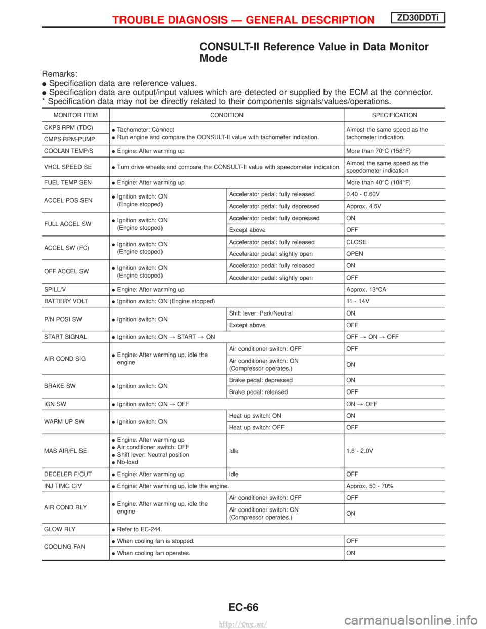
CONSULT-II Reference Value in Data Monitor
Mode
Remarks:
ISpecification data are reference values.
I Specification data are output/input values which are detected or supplied by the ECM at the connector.
* Specification data may not be directly related to their components signals/values/operations.
MONITOR ITEM CONDITION SPECIFICATION
CKPS×RPM (TDC) ITachometer: Connect
I Run engine and compare the CONSULT-II value with tachometer indication. Almost the same speed as the
tachometer indication.
CMPS×RPM-PUMP
COOLAN TEMP/S IEngine: After warming up More than 70ÉC (158ÉF)
VHCL SPEED SE ITurn drive wheels and compare the CONSULT-II value with speedometer indication. Almost the same speed as the
speedometer indication
FUEL TEMP SEN IEngine: After warming up More than 40ÉC (104ÉF)
ACCEL POS SEN I
Ignition switch: ON
(Engine stopped) Accelerator pedal: fully released
0.40 - 0.60V
Accelerator pedal: fully depressed Approx. 4.5V
FULL ACCEL SW I
Ignition switch: ON
(Engine stopped) Accelerator pedal: fully depressed ON
Except above
OFF
ACCEL SW (FC) I
Ignition switch: ON
(Engine stopped) Accelerator pedal: fully released
CLOSE
Accelerator pedal: slightly open OPEN
OFF ACCEL SW I
Ignition switch: ON
(Engine stopped) Accelerator pedal: fully released
ON
Accelerator pedal: slightly open OFF
SPILL/V IEngine: After warming up Approx. 13ÉCA
BATTERY VOLT IIgnition switch: ON (Engine stopped) 11 - 14V
P/N POSI SW IIgnition switch: ON Shift lever: Park/Neutral
ON
Except above OFF
START SIGNAL IIgnition switch: ON ,START ,ON OFF ,ON ,OFF
AIR COND SIG I
Engine: After warming up, idle the
engine Air conditioner switch: OFF OFF
Air conditioner switch: ON
(Compressor operates.)
ON
BRAKE SW IIgnition switch: ON Brake pedal: depressed ON
Brake pedal: released OFF
IGN SW IIgnition switch: ON ,OFF ON ,OFF
WARM UP SW IIgnition switch: ON Heat up switch: ON ON
Heat up switch: OFF OFF
MAS AIR/FL SE I
Engine: After warming up
I Air conditioner switch: OFF
I Shift lever: Neutral position
I No-load Idle 1.6 - 2.0V
DECELER F/CUT IEngine: After warming up Idle OFF
INJ TIMG C/V IEngine: After warming up, idle the engine. Approx. 50 - 70%
AIR COND RLY I
Engine: After warming up, idle the
engine Air conditioner switch: OFF OFF
Air conditioner switch: ON
(Compressor operates.)
ON
GLOW RLY IRefer to EC-244.
COOLING FAN I
When cooling fan is stopped. OFF
I When cooling fan operates. ON
TROUBLE DIAGNOSIS Ð GENERAL DESCRIPTIONZD30DDTi
EC-66
http://vnx.su/
Page 379 of 1833
Description
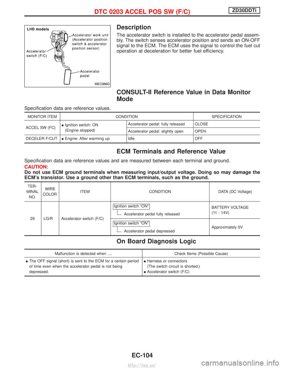
The accelerator switch is installed to the accelerator pedal assem-
bly. The switch senses accelerator position and sends an ON-OFF
signal to the ECM. The ECM uses the signal to control the fuel cut
operation at deceleration for better fuel efficiency.
CONSULT-II Reference Value in Data Monitor
Mode
Specification data are reference values.
MONITOR ITEMCONDITION SPECIFICATION
ACCEL SW (FC) I
Ignition switch: ON
(Engine stopped) Accelerator pedal: fully released CLOSE
Accelerator pedal: slightly open OPEN
DECELER F/CUT IEngine: After warming up Idle OFF
ECM Terminals and Reference Value
Specification data are reference values and are measured between each terminal and ground.
CAUTION:
Do not use ECM ground terminals when measuring input/output voltage. Doing so may damage the
ECM's transistor. Use a ground other than ECM terminals, such as the ground.
TER-
MINAL NO. WIRE
COLOR ITEM CONDITION DATA (DC Voltage)
29 LG/R Accelerator switch (F/C) Ignition switch ªONº
Accelerator pedal fully released
BATTERY VOLTAGE
(11 - 14V)
Ignition switch ªONº
Accelerator pedal depressed Approximately 0V
On Board Diagnosis Logic
Malfunction is detected when ....
Check Items (Possible Cause)
I The OFF signal (short) is sent to the ECM for a certain period
of time even when the accelerator pedal is not being
depressed. I
Harness or connectors
(The switch circuit is shorted.)
I Accelerator switch (F/C)
MEC986D
DTC 0203 ACCEL POS SW (F/C)ZD30DDTi
EC-104
http://vnx.su/
Page 406 of 1833
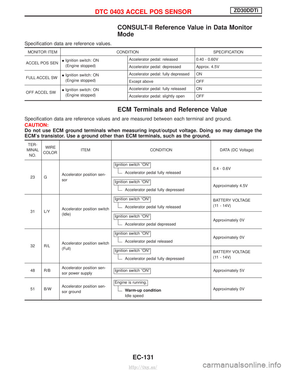
CONSULT-II Reference Value in Data Monitor
Mode
Specification data are reference values.
MONITOR ITEMCONDITION SPECIFICATION
ACCEL POS SEN I
Ignition switch: ON
(Engine stopped) Accelerator pedal: released 0.40 - 0.60V
Accelerator pedal: depressed Approx. 4.5V
FULL ACCEL SW I
Ignition switch: ON
(Engine stopped) Accelerator pedal: fully depressed ON
Except above OFF
OFF ACCEL SW I
Ignition switch: ON
(Engine stopped) Accelerator pedal: fully released ON
Accelerator pedal: slightly open OFF
ECM Terminals and Reference Value
Specification data are reference values and are measured between each terminal and ground.
CAUTION:
Do not use ECM ground terminals when measuring input/output voltage. Doing so may damage the
ECM's transistor. Use a ground other than ECM terminals, such as the ground.
TER-
MINAL NO. WIRE
COLOR ITEM CONDITION DATA (DC Voltage)
23 G Accelerator position sen-
sor Ignition switch ªONº
Accelerator pedal fully released
0.4 - 0.6V
Ignition switch ªONº
Accelerator pedal fully depressed Approximately 4.5V
31 L/Y Accelerator position switch
(Idle) Ignition switch ªONº
Accelerator pedal fully released
BATTERY VOLTAGE
(11 - 14V)
Ignition switch ªONº
Accelerator pedal depressed Approximately 0V
32 R/L Accelerator position switch
(Full) Ignition switch ªONº
Accelerator pedal released
Approximately 0V
Ignition switch ªONº
Accelerator pedal fully depressed BATTERY VOLTAGE
(11 - 14V)
48 R/B Accelerator position sen-
sor power supply Ignition switch ªONº
Approximately 5V
51 B/W Accelerator position sen-
sor ground Engine is running.
Warm-up condition
Idle speed
Approximately 0V
DTC 0403 ACCEL POS SENSORZD30DDTi
EC-131
http://vnx.su/
Page 591 of 1833
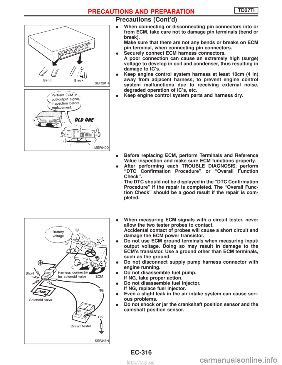
IWhen connecting or disconnecting pin connectors into or
from ECM, take care not to damage pin terminals (bend or
break).
Make sure that there are not any bends or breaks on ECM
pin terminal, when connecting pin connectors.
I Securely connect ECM harness connectors.
A poor connection can cause an extremely high (surge)
voltage to develop in coil and condenser, thus resulting in
damage to IC's.
I Keep engine control system harness at least 10cm (4 in)
away from adjacent harness, to prevent engine control
system malfunctions due to receiving external noise,
degraded operation of IC's, etc.
I Keep engine control system parts and harness dry.
I Before replacing ECM, perform Terminals and Reference
Value inspection and make sure ECM functions properly.
I After performing each TROUBLE DIAGNOSIS, perform
ªDTC Confirmation Procedureº or ªOverall Function
Checkº.
The DTC should not be displayed in the ªDTC Confirmation
Procedureº if the repair is completed. The ªOverall Func-
tion Checkº should be a good result if the repair is com-
pleted.
I When measuring ECM signals with a circuit tester, never
allow the two tester probes to contact.
Accidental contact of probes will cause a short circuit and
damage the ECM power transistor.
I Do not use ECM ground terminals when measuring input/
output voltage. Doing so may result in damage to the
ECM's transistor. Use a ground other than ECM terminals,
such as the ground.
I Do not disconnect supply pump harness connector with
engine running.
I Do not disassemble fuel pump.
If NG, take proper action.
I Do not disassemble fuel injector.
If NG, replace fuel injector.
I Even a slight leak in the air intake system can cause seri-
ous problems.
I Do not shock or jar the crankshaft position sensor and the
camshaft position sensor.
SEF291H
MEF040D
SEF348N
PRECAUTIONS AND PREPARATIONTD27Ti
Precautions (Cont'd)
EC-316
http://vnx.su/
Page 613 of 1833
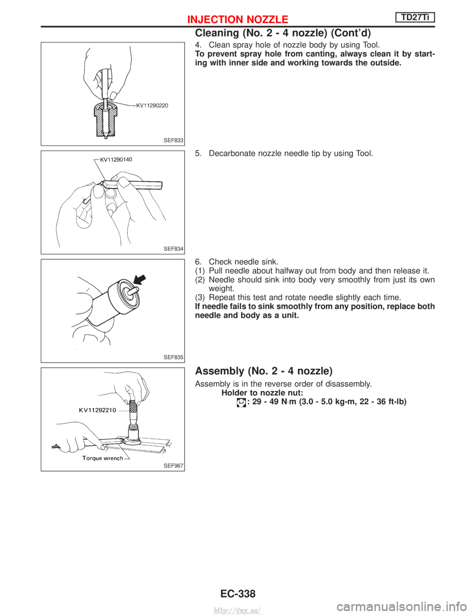
4. Clean spray hole of nozzle body by using Tool.
To prevent spray hole from canting, always clean it by start-
ing with inner side and working towards the outside.
5. Decarbonate nozzle needle tip by using Tool.
6. Check needle sink.
(1) Pull needle about halfway out from body and then release it.
(2) Needle should sink into body very smoothly from just its ownweight.
(3) Repeat this test and rotate needle slightly each time.
If needle fails to sink smoothly from any position, replace both
needle and body as a unit.
Assembly (No.2-4nozzle)
Assembly is in the reverse order of disassembly. Holder to nozzle nut:
:29-49N ×m (3.0 - 5.0 kg-m, 22 - 36 ft-lb)
SEF833
SEF834
SEF835
SEF967
INJECTION NOZZLETD27Ti
Cleaning (No.2-4nozzle) (Cont'd)
EC-338
http://vnx.su/