Page 75 of 1833
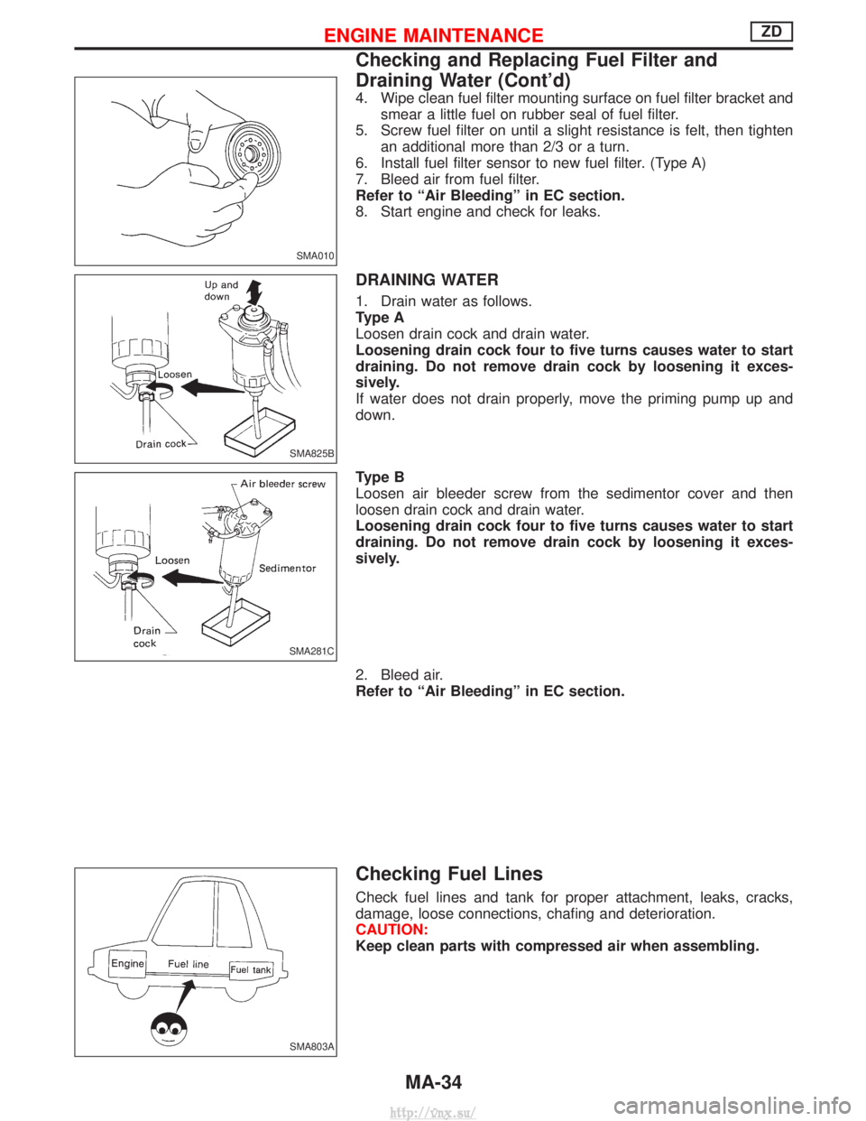
4. Wipe clean fuel filter mounting surface on fuel filter bracket andsmear a little fuel on rubber seal of fuel filter.
5. Screw fuel filter on until a slight resistance is felt, then tighten an additional more than 2/3 or a turn.
6. Install fuel filter sensor to new fuel filter. (Type A)
7. Bleed air from fuel filter.
Refer to ªAir Bleedingº in EC section.
8. Start engine and check for leaks.
DRAINING WATER
1. Drain water as follows.
Type A
Loosen drain cock and drain water.
Loosening drain cock four to five turns causes water to start
draining. Do not remove drain cock by loosening it exces-
sively.
If water does not drain properly, move the priming pump up and
down.
Type B
Loosen air bleeder screw from the sedimentor cover and then
loosen drain cock and drain water.
Loosening drain cock four to five turns causes water to start
draining. Do not remove drain cock by loosening it exces-
sively.
2. Bleed air.
Refer to ªAir Bleedingº in EC section.
Checking Fuel Lines
Check fuel lines and tank for proper attachment, leaks, cracks,
damage, loose connections, chafing and deterioration.
CAUTION:
Keep clean parts with compressed air when assembling.
SMA010
SMA825B
SMA281C
SMA803A
ENGINE MAINTENANCEZD
Checking and Replacing Fuel Filter and
Draining Water (Cont'd)
MA-34
http://vnx.su/
Page 115 of 1833
Removal and Installation
REMOVAL
1. Remove the following parts.
IRadiator under side
I Radiator shroud
I Cooling fan
I Chain cover front side
I A/T cooler hose (Disconnect)
I Vacuum hose
I Intercooler cover (When removing vacuum tank)
2. Remove the installation bolts and pull the vacuum pump from the engine front directly.
3. If it is difficult to remove from the spline shaft connection, tap lightly with a plastic hammer.
SEM320G
SEM321G
VACUUM PUMPZD
EM-24
http://vnx.su/
Page 137 of 1833
Installation
1. Install the front plate.
1) Install the O-ring and gasket to the cylinder block.
2) Install the front plate.
ILightly tap with a hammer if the dowel pin cannot be inserted
easily.
CAUTION:
Make sure that the O-ring does not pop out.
3) Apply Three Bond 1207C (KP510 00150) with a spreader between the cylinder block plate under the cylinder block (oil
pan side) and the front plate (shown by the arrows in the fig-
ure).
2. Install the fuel injection pump.
I After installing the front plate, align the 6 mm (0.24 in) dia. hole
of the pump flange and the 6 mm (0.24 in) dia. hole position of
the pump body.
3. Install each timing gear.
I Align the match marks of the timing gears by referring to the
figure below.
I When installing timing gear, follow the order ( q
1,q2) shown in
the dotted box in the figure below to facilitate installation.
SEM387G
FEM041
FEM042
TIMING GEARZD
Inspection (Cont'd)
EM-46
http://vnx.su/
Page 168 of 1833

CONNECTING ROD BEARING OIL CLEARANCE
Method by measurement
IInstall connecting rod bearings to connecting rods and caps,
and tighten connecting nuts to the specified torque. Use inside
micrometer to measure connecting rod bearing inner diameter.
Bearing clearance = Connecting rod bearing inner diameter þ
Crankshaft pin outer diameter
Standard: 0.035 - 0.077 mm (0.0014 - 0.0030 in)
I If out of specifications, check connecting rod big end inner
diameter and crankshaft pin outer diameter, and select appro-
priate connecting rod bearing to adjust clearance to specifica-
tions.
Refer to ªConnecting rod bearing undersize listº on the next
page.
Method using plastigage
IRemove contamination such as oil, dust completely from crank-
shaft pins and each bearing surface.
I Cut plastigage slightly shorter than bearing width, place it in
crankshaft direction, avoiding oil holes.
I Install connecting rod bearings to caps, and tighten connecting
rod nuts to the specified torque.
CAUTION:
Never rotate crankshaft.
I Remove connecting rod caps and bearings, and measure plas-
tigage width using scale on plastigage bag.
CAUTION:
If out of specification, take same action mentioned in ªMethod
by measurementº.
Undersize bearing usage
I If bearing clearance is out of specifications for connecting rod
bearings in standard size, use undersize bearings.
I When using undersize bearings, measure bearing inner diam-
eter with bearing installed, and grind pins to adjust clearance
to specification.
FEM103
FEM118
CYLINDER BLOCKZD
Inspection (Cont'd)
EM-77
http://vnx.su/
Page 169 of 1833
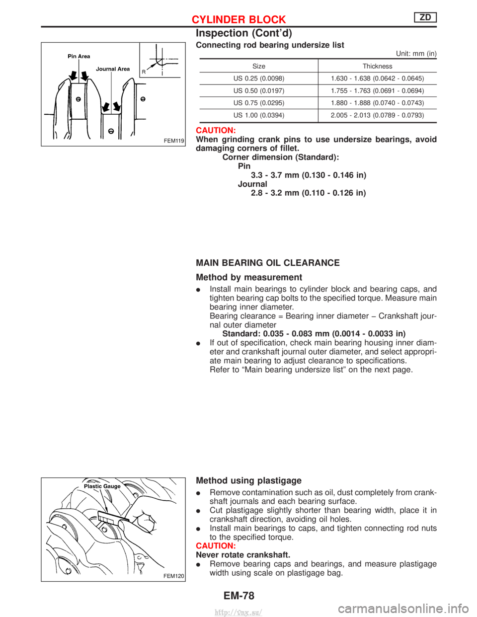
Connecting rod bearing undersize list
Unit: mm (in)
SizeThickness
US 0.25 (0.0098) 1.630 - 1.638 (0.0642 - 0.0645)
US 0.50 (0.0197) 1.755 - 1.763 (0.0691 - 0.0694)
US 0.75 (0.0295) 1.880 - 1.888 (0.0740 - 0.0743)
US 1.00 (0.0394) 2.005 - 2.013 (0.0789 - 0.0793)
CAUTION:
When grinding crank pins to use undersize bearings, avoid
damaging corners of fillet.
Corner dimension (Standard):Pin3.3 - 3.7 mm (0.130 - 0.146 in)
Journal 2.8 - 3.2 mm (0.110 - 0.126 in)
MAIN BEARING OIL CLEARANCE
Method by measurement
I Install main bearings to cylinder block and bearing caps, and
tighten bearing cap bolts to the specified torque. Measure main
bearing inner diameter.
Bearing clearance = Bearing inner diameter þ Crankshaft jour-
nal outer diameter
Standard: 0.035 - 0.083 mm (0.0014 - 0.0033 in)
I If out of specification, check main bearing housing inner diam-
eter and crankshaft journal outer diameter, and select appropri-
ate main bearing to adjust clearance to specifications.
Refer to ªMain bearing undersize listº on the next page.
Method using plastigage
IRemove contamination such as oil, dust completely from crank-
shaft journals and each bearing surface.
I Cut plastigage slightly shorter than bearing width, place it in
crankshaft direction, avoiding oil holes.
I Install main bearings to caps, and tighten connecting rod nuts
to the specified torque.
CAUTION:
Never rotate crankshaft.
I Remove bearing caps and bearings, and measure plastigage
width using scale on plastigage bag.
FEM119
FEM120
CYLINDER BLOCKZD
Inspection (Cont'd)
EM-78
http://vnx.su/
Page 284 of 1833
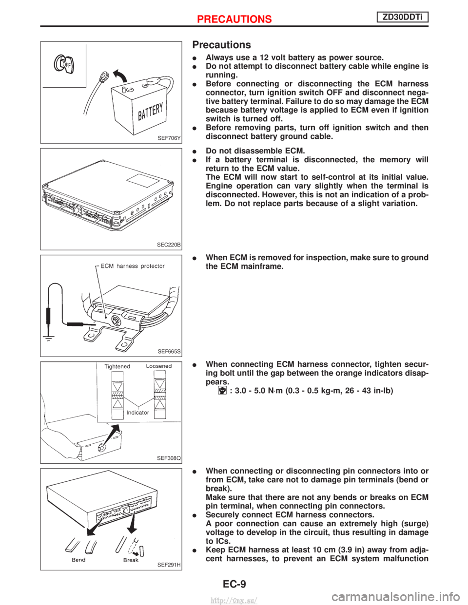
Precautions
IAlways use a 12 volt battery as power source.
I Do not attempt to disconnect battery cable while engine is
running.
I Before connecting or disconnecting the ECM harness
connector, turn ignition switch OFF and disconnect nega-
tive battery terminal. Failure to do so may damage the ECM
because battery voltage is applied to ECM even if ignition
switch is turned off.
I Before removing parts, turn off ignition switch and then
disconnect battery ground cable.
I Do not disassemble ECM.
I If a battery terminal is disconnected, the memory will
return to the ECM value.
The ECM will now start to self-control at its initial value.
Engine operation can vary slightly when the terminal is
disconnected. However, this is not an indication of a prob-
lem. Do not replace parts because of a slight variation.
I When ECM is removed for inspection, make sure to ground
the ECM mainframe.
I When connecting ECM harness connector, tighten secur-
ing bolt until the gap between the orange indicators disap-
pears.
: 3.0 - 5.0 N ×m (0.3 - 0.5 kg-m, 26 - 43 in-lb)
I When connecting or disconnecting pin connectors into or
from ECM, take care not to damage pin terminals (bend or
break).
Make sure that there are not any bends or breaks on ECM
pin terminal, when connecting pin connectors.
I Securely connect ECM harness connectors.
A poor connection can cause an extremely high (surge)
voltage to develop in the circuit, thus resulting in damage
to ICs.
I Keep ECM harness at least 10 cm (3.9 in) away from adja-
cent harnesses, to prevent an ECM system malfunction
SEF706Y
SEC220B
SEF665S
SEF308Q
SEF291H
PRECAUTIONSZD30DDTi
EC-9
http://vnx.su/
Page 286 of 1833
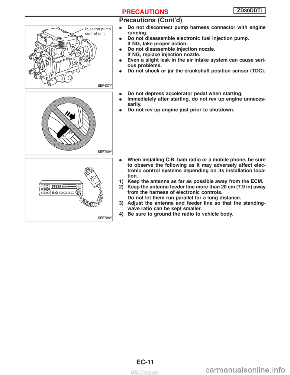
IDo not disconnect pump harness connector with engine
running.
I Do not disassemble electronic fuel injection pump.
If NG, take proper action.
I Do not disassemble injection nozzle.
If NG, replace injection nozzle.
I Even a slight leak in the air intake system can cause seri-
ous problems.
I Do not shock or jar the crankshaft position sensor (TDC).
I Do not depress accelerator pedal when starting.
I Immediately after starting, do not rev up engine unneces-
sarily.
I Do not rev up engine just prior to shutdown.
I When installing C.B. ham radio or a mobile phone, be sure
to observe the following as it may adversely affect elec-
tronic control systems depending on its installation loca-
tion.
1) Keep the antenna as far as possible away from the ECM.
2) Keep the antenna feeder line more than 20 cm (7.9 in) away from the harness of electronic controls.
Do not let them run parallel for a long distance.
3) Adjust the antenna and feeder line so that the standing- wave ratio can be kept smaller.
4) Be sure to ground the radio to vehicle body.
SEF437Y
SEF709Y
SEF708Y
PRECAUTIONSZD30DDTi
Precautions (Cont'd)
EC-11
http://vnx.su/
Page 308 of 1833
DTC and MI Detection Logic
When a malfunction is detected, the malfunction (DTC) is stored in the ECM memory.
The MI will light up each time the ECM detects malfunction. For diagnostic items causing the MI to light up,
refer to ªTROUBLE DIAGNOSIS Ð INDEXº, EC-7.
Diagnostic Trouble Code (DTC)
HOW TO READ DTC
The DTC can be read by the following methods.
Without CONSULT-II
ECM displays the DTC by a set of four digit numbers with MI illumination in the diagnostic test mode II (Self-
diagnostic results). Example: 0102, 0407, 1004, etc.
With CONSULT-II
CONSULT-II displays the DTC in ªSELF-DIAG RESULTSº mode. Examples: ªCRANK POS SEN (TDC)º, etc.
I Output of the trouble code means that the indicated circuit has a malfunction. However, in the Mode
II it does not indicate whether the malfunction is still occurring or occurred in the past and returned
to normal.
CONSULT-II can identify them. Therefore, using CONSULT-II (if available) is recommended.
HOW TO ERASE DTC
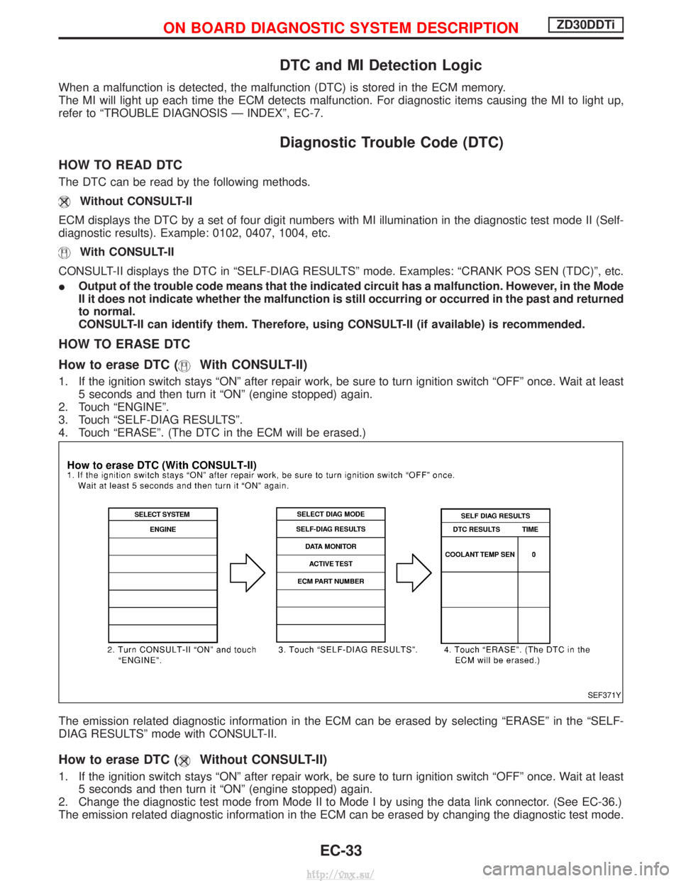
How to erase DTC (
With CONSULT-II)
1. If the ignition switch stays ªONº after repair work, be sure to turn ignition switch ªOFFº once. Wait at least
5 seconds and then turn it ªONº (engine stopped) again.
2. Touch ªENGINEº.
3. Touch ªSELF-DIAG RESULTSº.
4. Touch ªERASEº. (The DTC in the ECM will be erased.)
The emission related diagnostic information in the ECM can be erased by selecting ªERASEº in the ªSELF-
DIAG RESULTSº mode with CONSULT-II.
How to erase DTC (Without CONSULT-II)
1. If the ignition switch stays ªONº after repair work, be sure to turn ignition switch ªOFFº once. Wait at least 5 seconds and then turn it ªONº (engine stopped) again.
2. Change the diagnostic test mode from Mode II to Mode I by using the data link connector. (See EC-36.)
The emission related diagnostic information in the ECM can be erased by changing the diagnostic test mode.
SEF371Y
ON BOARD DIAGNOSTIC SYSTEM DESCRIPTIONZD30DDTi
EC-33
http://vnx.su/