Page 2614 of 3371
OIL PUMP
LU-13
C
D
E
F
G
H
I
J
K
L
MA
LU
Revision: August 20072004 QX56
OIL PUMPPFP:15010
Removal and InstallationEBS00I4N
REMOVAL
1. Remove front cover. Refer to EM-35, "TIMING CHAIN" .
2. Remove the oil pump drive spacer.
3. Remove the oil pump.
INSTALLATION
1. Installation is in the reverse order of removal, paying attention of the following:
�When inserting the oil pump drive spacer, align the crankshaft
key and the flat face of the inner rotor.
�If they are not aligned, rotate the oil pump inner rotor by hand.
�Make sure that each part is aligned and tap lightly until it
reached the end.
WBIA0415E
1. Oil pump body 2. Outer rotor 3. Inner rotor
4. Oil pump cover 5. Oil pump drive spacer 6. Regulator valve
7. Regulator spring 8. Regulator plug
KBIA2512E
KBIA2490E
Page 2616 of 3371
OIL PUMP
LU-15
C
D
E
F
G
H
I
J
K
L
MA
LU
Revision: August 20072004 QX56
2. Measure the inner diameter of oil pump body to brazed portion
(position 6) using suitable tool.
3. Calculate the clearance using the following formula.
�(Clearance) = (Inner diameter of oil pump body) - (Outer diameter of inner rotor)
Regulator Valve Clearance
Check regulator valve to oil pump cover clearance as follows:
�(Clearance) = D1 (Valve hole diameter) - D2 (Outer Diameter
of valve)
CAUTION:
�Coat regulator valve with engine oil.
�Check that it falls smoothly into the regulator valve hole
by its own weight.
ASSEMBLY
Installation is in the reverse order of removal.
NOTE:
Install the inner rotor and outer rotor with the punched marks on the
oil pump cover side.
PBIC0142E
Inner rotor to brazed portion of housing
clearance
: 0.045 - 0.091 mm (0.0018 - 0.0036 in)
Regulator valve to oil pump cover
: 0.040 - 0.097 mm (0.0016 - 0.0038 in)
PBIC0143E
PBIC0144E
Page 2636 of 3371
ENGINE MAINTENANCE
MA-19
C
D
E
F
G
H
I
J
K
MA
B
MA
Revision: August 20072004 QX56
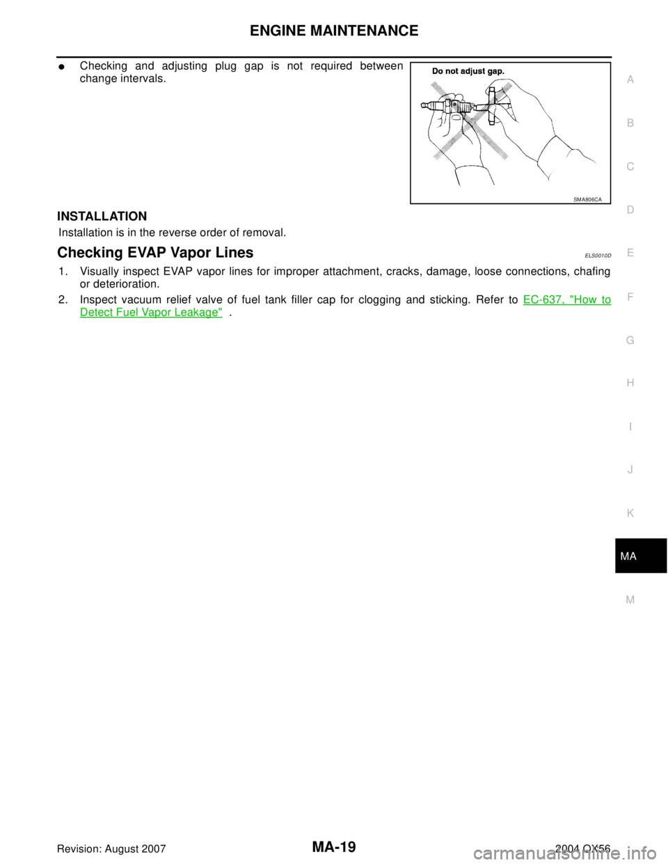
�Checking and adjusting plug gap is not required between
change intervals.
INSTALLATION
Installation is in the reverse order of removal.
Checking EVAP Vapor LinesELS0010D
1. Visually inspect EVAP vapor lines for improper attachment, cracks, damage, loose connections, chafing
or deterioration.
2. Inspect vacuum relief valve of fuel tank filler cap for clogging and sticking. Refer to EC-637, "
How to
Detect Fuel Vapor Leakage" .
SM A80 6CA
Page 2638 of 3371

CHASSIS AND BODY MAINTENANCE
MA-21
C
D
E
F
G
H
I
J
K
MA
B
MA
Revision: August 20072004 QX56
5. Insert the first new in-cabin microfilter into the front heater and
cooling unit assembly housing and slide it over to the right.
Insert the second new in-cabin microfilter into the front heater
and cooling unit assembly housing.
NOTE:
The in-cabin microfilters are marked with air flow arrows. The
end of the microfilter with the arrow should face the rear of the
vehicle. The arrows should point downward.
6. Install the in-cabin microfilter cover.
7. Install the glove box assembly in reverse order of removal.
8. Install the instrument lower cover RH.
Checking Exhaust SystemELS0010F
Check exhaust pipes, muffler and mounting for improper attachment,
leaks, cracks, damage, loose connections, chafing or deterioration.
Checking A/T FluidELS001JM
1. Warm up the engine.
2. Check for any fluid leakage.
3. Remove the tightening bolt for the ATF level gauge.
LJIA0148E
LJIA0134E
Upper glove box screws : 3.5 N·m (0.36 kg-m, 31 in-lb)
Lower glove box screws : 3.5 N·m (0.36 kg-m, 31 in-lb)
LLIA0072E
SM A211 A
Page 2639 of 3371
 using
“COLD” range on ATF le")
MA-22
CHASSIS AND BODY MAINTENANCE
Revision: August 20072004 QX56
4. Before driving, fluid level can be checked at fluid temperatures of 30° to 50°C (86° to 122°F) using
“COLD” range on ATF level gauge as follows.
a. Park vehicle on level surface and set parking brake.
b. Start engine and move selector lever through each gear position. Leave selector lever in “P” position.
c. Check fluid level with engine idling.
d. Remove ATF level gauge and wipe clean with lint-free paper.
CAUTION:
When wiping away the fluid level gauge, always use lint-free paper, not a cloth one.
e. Re-insert ATF level gauge into charging pipe as far as it will go.
CAUTION:
To check fluid level, insert the ATF level gauge until the cap
contacts the end of the charging pipe, with the gauge
reversed from the normal attachment conditions.
f. Remove ATF level gauge and note reading. If reading is at low
side of range, add fluid to the charging pipe.
CAUTION:
Do not overfill.
5. Increase ATF temperature by 80°C (176°F) once.
6. Make the fluid temperature approximately 65°C (149°F).
NOTE:
Fluid level will be greatly affected by temperature as shown. Therefore, be certain to perform oper-
ation while checking data with CONSULT-II.
a. Connect CONSULT-II to data link connector.
SCIA1684E
WLIA0014E
SLIA0016E
Page 2640 of 3371

CHASSIS AND BODY MAINTENANCE
MA-23
C
D
E
F
G
H
I
J
K
MA
B
MA
Revision: August 20072004 QX56
b. Select “MAIN SIGNALS” in “DATA MONITOR” mode for “A/T” with CONSULT-II.
c. Read out the value of “ATF TEMP 1”.
7. Re-check fluid level at fluid temperatures of approximately 65°C
(149°F) using “HOT” range on A/T fluid level gauge.
CAUTION:
�When wiping away the fluid level gauge, always use lint-
free paper, not a cloth one.
�To check fluid level, insert the ATF level gauge until the
cap contacts the end of the charging pipe, with the gauge
reversed from the normal attachment conditions as
shown.
8. Check fluid condition.
�If fluid is very dark or smells burned, refer to check operation
of A/T. Flush cooling system after repair of A/T.
�If ATF contains frictional material (clutches, bands, etc.),
replace radiator and flush cooler line using cleaning solvent
and compressed air after repair of A/T. Refer to CO-10,
"RADIATOR" and AT-15, "A/T Fluid Cooler Cleaning" .
9. Install the removed ATF level gauge into the fluid charging pipe.
Changing A/T FluidELS001JN
1. Increase ATF temperature by 80°C (176°F) once.
2. Stop the engine.
3. Remove the tightening bolt for the ATF level gauge.
4. Drain ATF from drain plug and refill with new ATF. Always refill same volume with drained fluid.
�To replace the ATF, pour in new fluid at the charging pipe with the engine idling and at the same time
drain the old fluid from the radiator cooler hose return side.
�When the color of the fluid coming out is about the same as the color of the new fluid, the replacement
is complete. The amount of new transmission fluid to use should be 30 to 50% increase of the stipu-
lated amount.
CAUTION:
�Use only specified ATF fluid. Do not mix with other fluid.
�Using ATF other than the specified ATF fluid will cause deterioration in driveability and auto-
matic transmission durability, and may damage the automatic transmission, which is not cov-
ered by the warranty.
�When filling ATF, take care not to splash any heat generating parts such as the exhaust.
5. Increase ATF temperature by 80°C (176°F) once.
6. Check fluid level and condition. Refer to MA-21, "
Checking A/T Fluid" . If fluid is still dirty, repeat step 2.
through 5.
7. Install the removed ATF level gauge in the fluid charging pipe.
WLIA0014E
Level gauge bolt : Refer to AT-13, "A/T FLUID" .
SCIA1684E
ATF fluid capacity and specification : Refer to MA-10, "Fluids and Lubricants" .
Drain plug : Refer to AT-13, "
A/T FLUID" .
Level gauge bolt : Refer to AT- 1 3 , "
A/T FLUID" .
Page 2654 of 3371
PARKING BRAKE CONTROL
PB-5
C
D
E
G
H
I
J
K
L
MA
B
PB
Revision: August 20072004 QX56
INSTALLATION
�Installation is in the reverse order of removal.
CAUTION:
Do not reuse adjusting nut after removing it.
�Adjust parking brake. Refer to PB-3, "ADJUSTMENT" .
Page 2656 of 3371

PARKING BRAKE SHOE
PB-7
C
D
E
G
H
I
J
K
L
MA
B
PB
Revision: August 20072004 QX56
INSPECTION AFTER REMOVAL
Lining Thickness Inspection
�Check thickness of lining.
Drum Inner Diameter Inspection
�Check drum inner diameter.
Other Inspections
�Check shoe sliding surface for excessive wear and damage.
�Check anti-rattle pin for excessive wear and corrosion.
�Check return spring for sagging.
�Check adjuster for rough operation.
�When disassembling adjuster, apply PBC (Poly Butyl Cuprysil) grease or equivalent to the adjuster
threads. Refer to MA-10, "
RECOMMENDED FLUIDS AND LUBRICANTS" .
�Check either visually or with a vernier caliper to see if there is any excessive wear, cracks, or damage
inside drum.
INSTALLATION
Installation is in the reverse order of removal.
�Apply brake grease to the specified points during assembly. Refer to PB-6, "COMPONENTS" .
�Install adjuster so that threaded part expands when rotating it in
the direction shown by the arrow.
�Shorten adjuster by rotating it in the oposite direction as shown
by the arrow.
NOTE:
After replacing brake shoes or disc rotors, or if parking brake does
not function well, perform break-in operation as follows.
1. Adjust parking brake pedal stroke. Refer to PB-3, "
ADJUST-
MENT" .
2. Perform parking brake burnishing operation by driving the vehicle forward under the following conditions:Standard thickness "A" : 5.15 ± 0.25 mm
(0.203 ± 0.010 in)
Repair limit thickness "A" : 0.5 mm (0.020 in)
SBR0 21 A
Standard inner
diameter: 205 ± 0.13 mm (8.07 ± 0.01 in)
Maximum inner
diameter: 205.7 mm (8.10 in)
SBR7 68 A
SFIA0153E
�Vehicle speed 40 km/h (25 MPH) set (forward)
�Parking brake operating force 196 N (20.0 kg, 44.1 lb) set
�Apply time 30 sec.

 using suitable tool.
3. Calculate the clearance us")