Page 2688 of 3371
IPDM E/R (INTELLIGENT POWER DISTRIBUTION MODULE ENGINE ROOM)
PG-29
C
D
E
F
G
H
I
J
L
MA
B
PG
Revision: August 20072004 QX56
Removal and Installation of IPDM E/REKS007NW
REMOVAL
1. Disconnect negative battery cable.
2. Remove IPDM E/R upper cover.
3. Release 2 clips and pull IPDM E/R up from case.
4. Disconnect IPDM E/R connectors and remove the IPDM E/R.
INSTALLATION
Installation is in the reverse order of removal.
WKIA1454E
WKIA1696E
Page 2742 of 3371
FRONT PROPELLER SHAFT
PR-5
C
E
F
G
H
I
J
K
L
MA
B
PR
Revision: August 20072004 QX56
REMOVAL
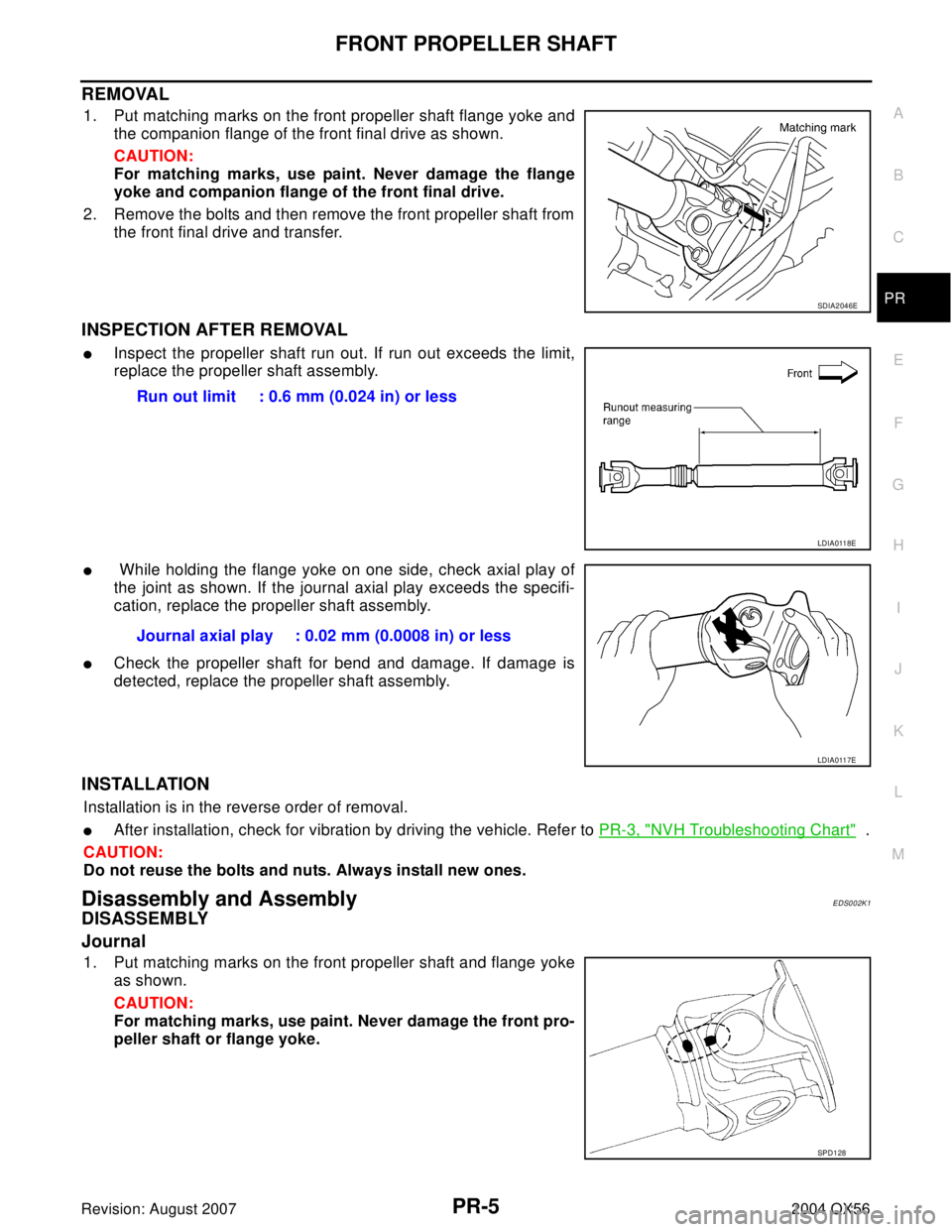
1. Put matching marks on the front propeller shaft flange yoke and
the companion flange of the front final drive as shown.
CAUTION:
For matching marks, use paint. Never damage the flange
yoke and companion flange of the front final drive.
2. Remove the bolts and then remove the front propeller shaft from
the front final drive and transfer.
INSPECTION AFTER REMOVAL
�Inspect the propeller shaft run out. If run out exceeds the limit,
replace the propeller shaft assembly.
� While holding the flange yoke on one side, check axial play of
the joint as shown. If the journal axial play exceeds the specifi-
cation, replace the propeller shaft assembly.
�Check the propeller shaft for bend and damage. If damage is
detected, replace the propeller shaft assembly.
INSTALLATION
Installation is in the reverse order of removal.
�After installation, check for vibration by driving the vehicle. Refer to PR-3, "NVH Troubleshooting Chart" .
CAUTION:
Do not reuse the bolts and nuts. Always install new ones.
Disassembly and AssemblyEDS002K1
DISASSEMBLY
Journal
1. Put matching marks on the front propeller shaft and flange yoke
as shown.
CAUTION:
For matching marks, use paint. Never damage the front pro-
peller shaft or flange yoke.
SDIA2046E
Run out limit : 0.6 mm (0.024 in) or less
LDIA0118E
Journal axial play : 0.02 mm (0.0008 in) or less
LDIA0117E
SPD1 28
Page 2746 of 3371
REAR PROPELLER SHAFT
PR-9
C
E
F
G
H
I
J
K
L
MA
B
PR
Revision: August 20072004 QX56
REMOVAL
1. Move the A/T select lever to the N position and release the parking brake.
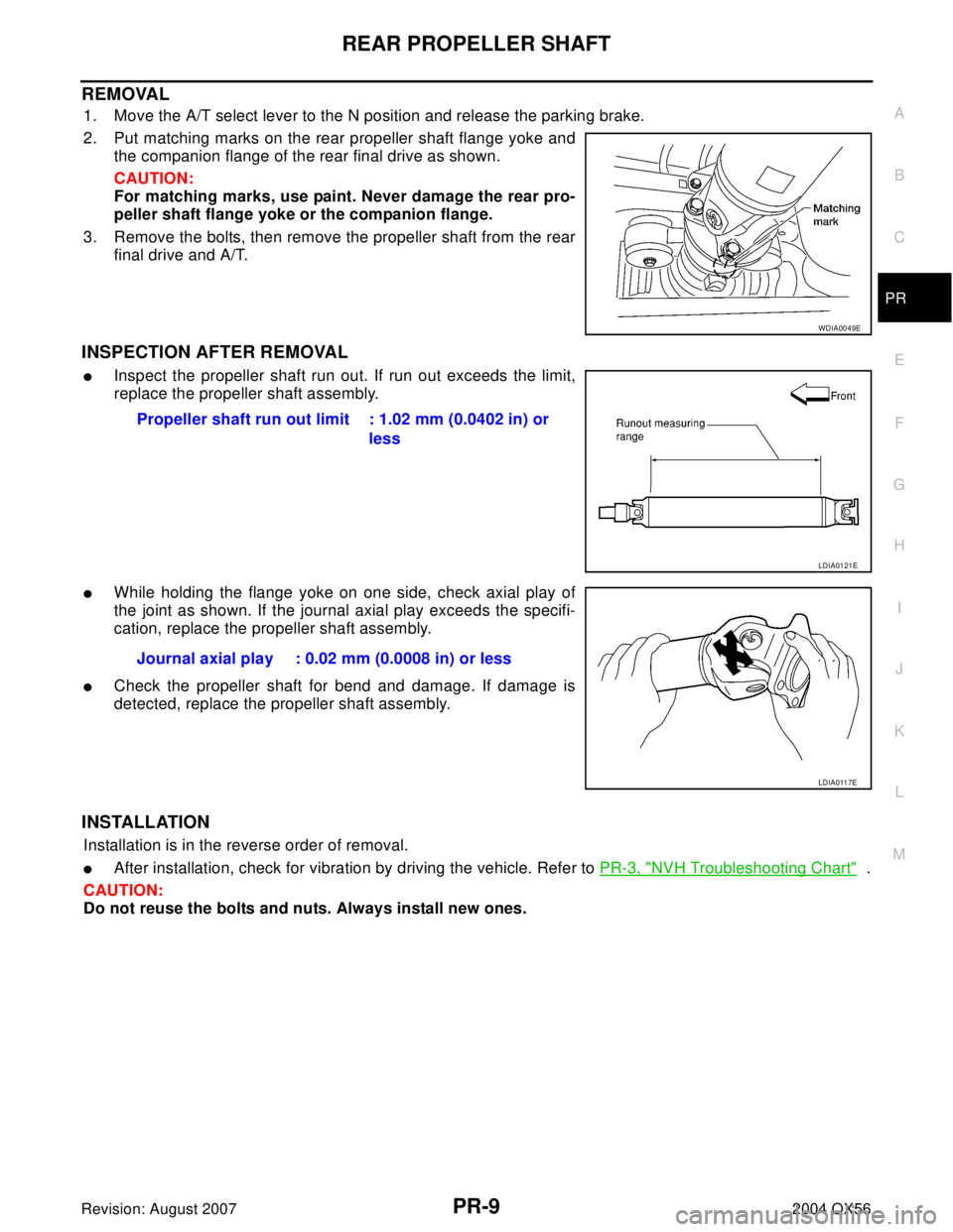
2. Put matching marks on the rear propeller shaft flange yoke and
the companion flange of the rear final drive as shown.
CAUTION:
For matching marks, use paint. Never damage the rear pro-
peller shaft flange yoke or the companion flange.
3. Remove the bolts, then remove the propeller shaft from the rear
final drive and A/T.
INSPECTION AFTER REMOVAL
�Inspect the propeller shaft run out. If run out exceeds the limit,
replace the propeller shaft assembly.
�While holding the flange yoke on one side, check axial play of
the joint as shown. If the journal axial play exceeds the specifi-
cation, replace the propeller shaft assembly.
�Check the propeller shaft for bend and damage. If damage is
detected, replace the propeller shaft assembly.
INSTALLATION
Installation is in the reverse order of removal.
�After installation, check for vibration by driving the vehicle. Refer to PR-3, "NVH Troubleshooting Chart" .
CAUTION:
Do not reuse the bolts and nuts. Always install new ones.
WDIA0049E
Propeller shaft run out limit : 1.02 mm (0.0402 in) or
less
LDIA0121E
Journal axial play : 0.02 mm (0.0008 in) or less
LDIA0117E
Page 2759 of 3371
PS-8
STEERING WHEEL
Revision: August 20072004 QX56
Removal and InstallationEGS000MR
REMOVAL
1. Set the front wheels in the straight-ahead position.
2. Remove the driver air bag module. Refer to SRS-45, "
Removal and Installation" .
3. Disconnect steering wheel switches.
4. Remove the steering wheel center nut.
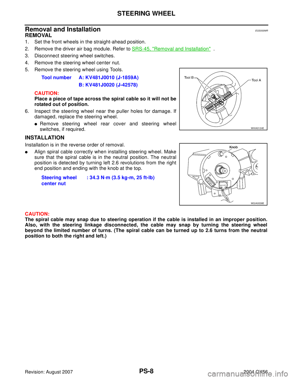
5. Remove the steering wheel using Tools.
CAUTION:
Place a piece of tape across the spiral cable so it will not be
rotated out of position.
6. Inspect the steering wheel near the puller holes for damage. If
damaged, replace the steering wheel.
�Remove steering wheel rear cover and steering wheel
switches, if required.
INSTALLATION
Installation is in the reverse order of removal.
�Align spiral cable correctly when installing steering wheel. Make
sure that the spiral cable is in the neutral position. The neutral
position is detected by turning left 2.6 revolutions from the right
end position and ending with the knob at the top.
CAUTION:
The spiral cable may snap due to steering operation if the cable is installed in an improper position.
Also, with the steering linkage disconnected, the cable may snap by turning the steering wheel
beyond the limited number of turns. (The spiral cable can be turned up to 2.6 turns from the neutral
position to both the right and left.)Tool number A: KV481J0010 (J-1859A)
B: KV481J0020 (J-42578)
WHIA0124E
Steering wheel
center nut : 34.3 N·m (3.5 kg-m, 25 ft-lb)
WGIA0038E
Page 2760 of 3371
TILT SYSTEM
PS-9
C
D
E
F
H
I
J
K
L
MA
B
PS
Revision: August 20072004 QX56
TILT SYSTEMPFP:48810
Removal and InstallationEGS000N8
TILT MOTOR AND TILT SENSOR
Removal
1. Remove the steering column cover and lower driver instrument panel. Refer to IP-10, "INSTRUMENT
PANEL ASSEMBLY" .
2. Remove knee protector.
3. Disconnect the tilt sensor electrical connector.
4. Remove the two tilt sensor screws and the tilt sensor.
5. Disconnect the tilt motor electrical connector.
6. Remove the tilt motor bolt and the tilt motor.
Installation
Installation is in reverse order of removal.
NOTE:
Make sure the tab in the tilt sensor is engaged in the bracket on the tilt motor.
LGIA0022E
1. Tilt sensor 2. Tilt motor
LGIA0026E
Page 2762 of 3371
STEERING COLUMN
PS-11
C
D
E
F
H
I
J
K
L
MA
B
PS
Revision: August 20072004 QX56
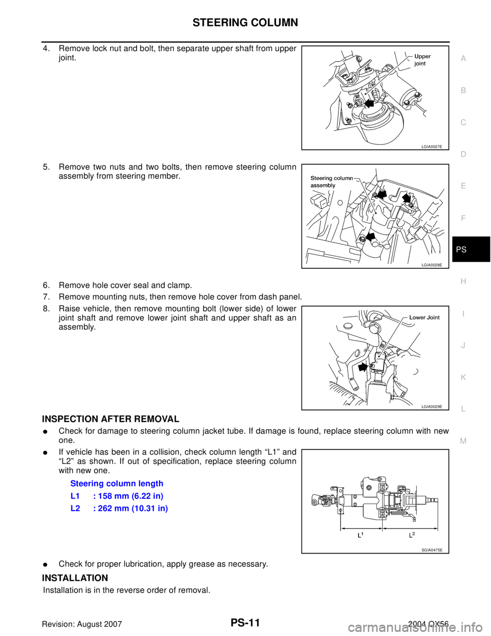
4. Remove lock nut and bolt, then separate upper shaft from upper
joint.
5. Remove two nuts and two bolts, then remove steering column
assembly from steering member.
6. Remove hole cover seal and clamp.
7. Remove mounting nuts, then remove hole cover from dash panel.
8. Raise vehicle, then remove mounting bolt (lower side) of lower
joint shaft and remove lower joint shaft and upper shaft as an
assembly.
INSPECTION AFTER REMOVAL
�Check for damage to steering column jacket tube. If damage is found, replace steering column with new
one.
�If vehicle has been in a collision, check column length “L1” and
“L2” as shown. If out of specification, replace steering column
with new one.
�Check for proper lubrication, apply grease as necessary.
INSTALLATION
Installation is in the reverse order of removal.
LGIA0027E
LGIA0028E
LGIA0029E
Steering column length
L1 : 158 mm (6.22 in)
L2 : 262 mm (10.31 in)
SGIA0475E
Page 2765 of 3371
PS-14
STEERING COLUMN
Revision: August 20072004 QX56
ASSEMBLY
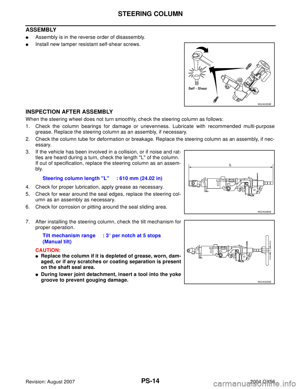
�Assembly is in the reverse order of disassembly.
�Install new tamper resistant self-shear screws.
INSPECTION AFTER ASSEMBLY
When the steering wheel does not turn smoothly, check the steering column as follows:
1. Check the column bearings for damage or unevenness. Lubricate with recommended multi-purpose
grease. Replace the steering column as an assembly, if necessary.
2. Check the column tube for deformation or breakage. Replace the steering column as an assembly, if nec-
essary.
3. If the vehicle has been involved in a collision, or if noise and rat-
tles are heard during a turn, check the length "L" of the column.
If out of specification, replace the steering column as an assem-
bly.
4. Check for proper lubrication, apply grease as necessary.
5. Check for wear around the seal edges, replace the steering col-
umn as an assembly as necessary.
6. Check for corrosion or pitting around the seal sliding area.
7. After installing the steering column, check the tilt mechanism for
proper operation.
CAUTION:
�Replace the column if it is depleted of grease, worn, dam-
aged, or if any scratches or coating separation is present
on the shaft seal area.
�During lower joint detachment, insert a tool into the yoke
groove to prevent gouging damage.
WGIA0009E
Steering column length "L" : 610 mm (24.02 in)
WGIA0080E
Tilt mechanism range
(Manual tilt): 3° per notch at 5 stops
WGIA0026E
Page 2767 of 3371
PS-16
POWER STEERING GEAR AND LINKAGE
Revision: August 20072004 QX56
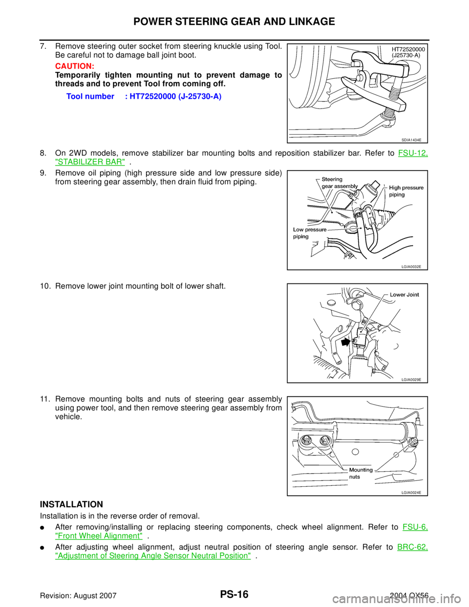
7. Remove steering outer socket from steering knuckle using Tool.
Be careful not to damage ball joint boot.
CAUTION:
Temporarily tighten mounting nut to prevent damage to
threads and to prevent Tool from coming off.
8. On 2WD models, remove stabilizer bar mounting bolts and reposition stabilizer bar. Refer to FSU-12,
"STABILIZER BAR" .
9. Remove oil piping (high pressure side and low pressure side)
from steering gear assembly, then drain fluid from piping.
10. Remove lower joint mounting bolt of lower shaft.
11. Remove mounting bolts and nuts of steering gear assembly
using power tool, and then remove steering gear assembly from
vehicle.
INSTALLATION
Installation is in the reverse order of removal.
�After removing/installing or replacing steering components, check wheel alignment. Refer to FSU-6,
"Front Wheel Alignment" .
�After adjusting wheel alignment, adjust neutral position of steering angle sensor. Refer to BRC-62,
"Adjustment of Steering Angle Sensor Neutral Position" . Tool number : HT72520000 (J-25730-A)
SDIA1434E
LGIA0032E
LGIA0029E
LGIA0024E