Page 2895 of 3371
RSU-36
SUSPENSION ARM
Revision: August 20072004 QX56
�Check the ball joint. Replace the suspension arm assembly if
any of the following conditions exist:
–Ball stud is worn.
–Joint is hard to swing.
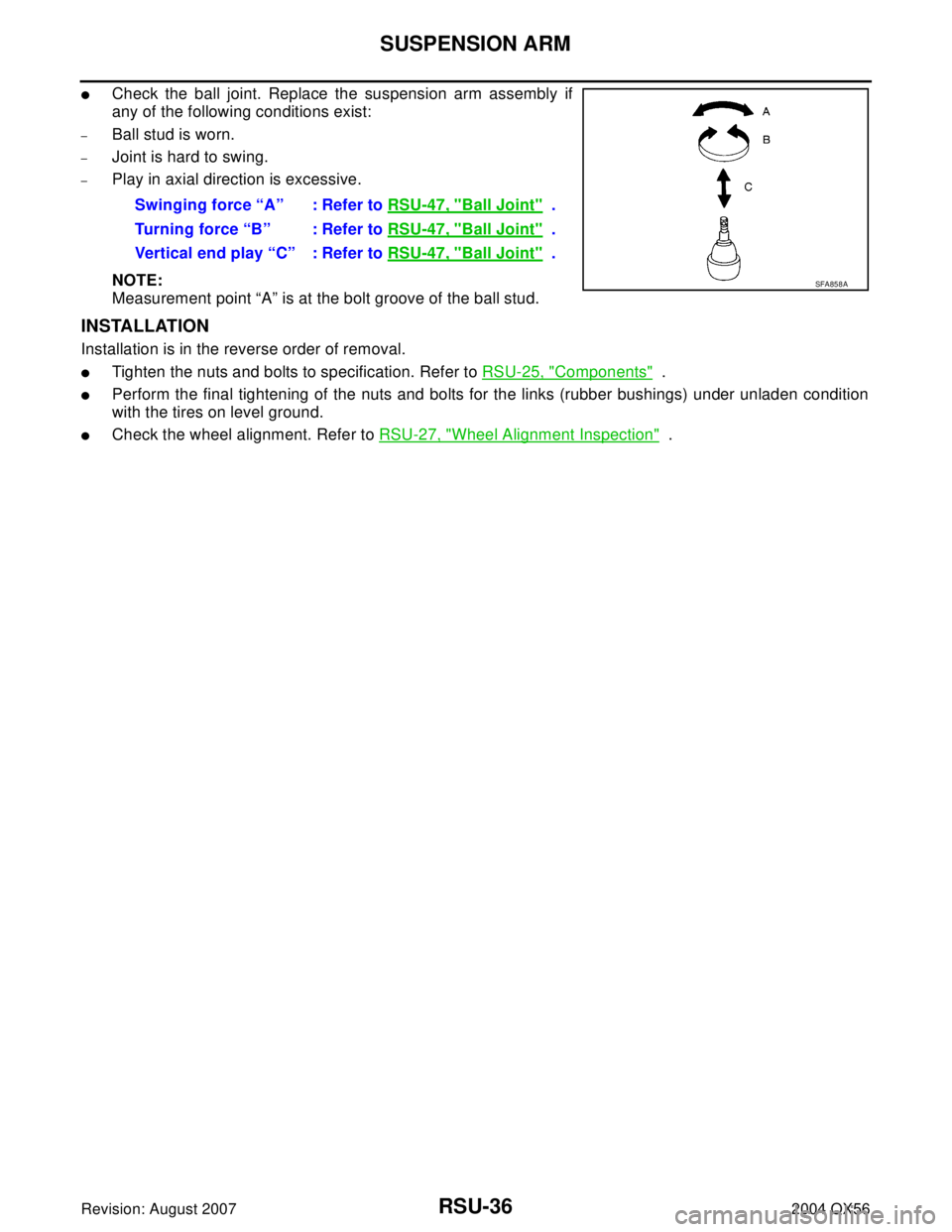
–Play in axial direction is excessive.
NOTE:
Measurement point “A” is at the bolt groove of the ball stud.
INSTALLATION
Installation is in the reverse order of removal.
�Tighten the nuts and bolts to specification. Refer to RSU-25, "Components" .
�Perform the final tightening of the nuts and bolts for the links (rubber bushings) under unladen condition
with the tires on level ground.
�Check the wheel alignment. Refer to RSU-27, "Wheel Alignment Inspection" . Swinging force “A” : Refer to RSU-47, "
Ball Joint" .
Turning force “B” : Refer to RSU-47, "
Ball Joint" .
Vertical end play “C” : Refer to RSU-47, "
Ball Joint" .
SFA858A
Page 2897 of 3371
RSU-38
FRONT LOWER LINK
Revision: August 20072004 QX56
NOTE:
Measurement point “A” is at the bolt groove of the ball stud.
INSTALLATION
Installation is in the reverse order of removal.
�Tighten the nuts and bolts to specification. Refer to RSU-25, "Components" .
�Perform the final tightening of the front lower link nuts and bolts (with rubber bushings) under unladen
condition with tires on level ground.
�Check the wheel alignment. Refer to RSU-27, "Wheel Alignment Inspection" .
Page 2899 of 3371
RSU-40
REAR LOWER LINK & COIL SPRING
Revision: August 20072004 QX56
8. Remove the rear lower link adjusting bolt and nut from the rear
suspension member using power tool, then remove the rear
lower link.
INSPECTION AFTER REMOVAL
Check the coil spring and rubber seats for deformation, cracks, or other damage and replace if necessary.
INSTALLATION
Installation is in the reverse order of removal.
�Tighten the nuts and bolts to specification. Refer to RSU-25, "Components" .
�When installing the upper and lower rubber seats for the rear
coil springs, the arrow embossed on the rubber seats must point
out toward the wheel and tire assembly.
�After installing the rear lower link and coil spring, check the
wheel alignment and adjust if necessary. Refer to RSU-27,
"Wheel Alignment Inspection" .
LEIA0009E
LEIA0076E
Page 2900 of 3371
STABILIZER BAR
RSU-41
C
D
F
G
H
I
J
K
L
MA
B
RSU
Revision: August 20072004 QX56
STABILIZER BARPFP:56230
Removal and Installation EES0011R
REMOVAL
1. Disconnect the stabilizer bar ends from the connecting rods
using power tool.
2. Remove the stabilizer bar clamps using power tool, and remove
the stabilizer bar bushings.
3. Remove the stabilizer bar.
INSTALLATION
Installation is in the reverse order of removal.
�Tighten the nuts and bolts to specification. Refer to RSU-25, "Components" .
�Install the stabilizer bar with the ball joint sockets properly
aligned.
�Install the stabilizer bar bushing and clamp so they are posi-
tioned inside of the sideslip prevention clamp on the stabilizer
bar.
InspectionEES0011S
�Check stabilizer bar for any deformation, cracks, or damage and replace if necessary.
�Check rubber bushings for deterioration, or cracks and replace if necessary.
LEIA0088E
LEIA0089E
SFA449BB
Page 2902 of 3371
REAR LOAD LEVELING AIR SUSPENSION COMPRESSOR ASSEMBLY
RSU-43
C
D
F
G
H
I
J
K
L
MA
B
RSU
Revision: August 20072004 QX56
5. Remove the four bolts that mount the rear load leveling air sus-
pension compressor assembly to the underbody.
INSTALLATION
Installation is in the reverse order of removal.
�To connect the rear load leveling air suspension hoses, the lock
ring must be fully seated in the fitting. Insert the hose “B” into the
lock ring “A” until the lock ring “A” is touching the hose “B” as
shown. Pull on the hose to check that it is securely inserted.
LEIA0090E
LEIA0078E
Page 2904 of 3371
HEIGHT SENSOR
RSU-45
C
D
F
G
H
I
J
K
L
MA
B
RSU
Revision: August 20072004 QX56
INSTALLATION
Installation is in the reverse order of removal.
1. Start the engine.
2. Use CONSULT-II to perform "STANDARD HEIGHT LEVEL" work support function.
3. Using data monitor of CONSULT-II, verify "HEIGT CALC" is at 0 mm.
4. Check the vehicle height. Refer to RSU-48, "
Wheelarch Height (Unladen*1 )" . If vehicle height is not
within ± 10 mm (0 ± 0.39 in) of the specification, perform the initialization procedure. Refer to RSU-46,
"Initialization Procedure" .
Page 2905 of 3371

RSU-46
CONTROL UNIT
Revision: August 20072004 QX56
CONTROL UNITPFP:47850
Removal and InstallationEES0011V
REMOVAL
1. Remove the rear LH interior trim panel. Refer to EI-34, "BODY SIDE TRIM" .
2. Disconnect the battery negative terminal.
3. Disconnect the suspension control unit electrical connector.
4. Remove the two bolts and remove the suspension control unit.
INSTALLATION
Installation is in the reverse order of removal.
Initialization ProcedureEES0011W
1. If control unit has been replaced, proceed to step 2. If control unit has not been replaced, use CONSULT-
II “CLEAR HEIGHT INI” work support function to clear initialization flag and value. The CK SUSP warning
lamp should illuminate. Using CONSULT-II “EXHAUST SOLENOID” active test, release the air pressure
from the rear load leveling air suspension system.
2. Roll vehicle forward and backward.
3. Use CONSULT-II “ADJUST HEIGHT INI” work support function to set initialization condition.
4. Confirm that CK SUSP warning lamp is OFF.
LEIA0100E
Suspension control unit bolts : 6 N·m (0.6 kg-m, 53 in-lb)
Page 2911 of 3371

SB-4
SEAT BELTS
Revision: August 20072004 QX56
REMOVAL OF SEAT BELT RETRACTOR
CAUTION:
�Before servicing SRS, turn the ignition switch off, disconnect both battery cables and wait at least
3 minutes.
1. Remove the center pillar upper/lower finishers. Refer to EI-34, "
BODY SIDE TRIM" .
2. Remove the seat belt retractor anchor bolts and seat belt retractor and belt assembly.
�On RH side, disconnect the seat belt tension sensor.
3. Disconnect the seat belt pre-tensioner electrical connector.
CAUTION:
�For installing/removing seat belt pre-tensioner connector,
insert a thin screwdriver wrapped in tape into the notch, lift
the lock and remove the connector.
�Install the connector with the lock raised, and push the lock
into the connector.
INSTALLATION OF SEAT BELT RETRACTOR
Installation is in the reverse order of removal.
�Install the seat belt retractor and belt assembly upper bolt first.
�Ensure that seat belt height adjuster is locked in the lowest position during installation.
WHIA0237E
PHIA0341E