Page 2777 of 3371

PS-26
POWER STEERING OIL PUMP
Revision: August 20072004 QX56
POWER STEERING OIL PUMPPFP:49110
On-Vehicle Inspection and ServiceEGS000MW
CHECKING RELIEF OIL PRESSURE
CAUTION:
Before starting work, confirm belt tension is proper.
1. Connect Tool between oil pump discharge connector and high
pressure hose and then bleed air from the hydraulic circuit.
2. Start engine. Allow engine to run until tank temperature reaches 50 – 80°C (122 – 176°F).
CAUTION:
�Warm up engine with shut-off valve fully opened. If engine is started with shut-off valve closed,
fluid pressure in power steering pump increases to maximum. This will raise fluid temperature
excessively.
�Be careful not to contact hose with belt when engine is started.
3. With engine at idle, close shut-off valve and read the relief oil pressure.
CAUTION:
Do not close shut-off valve of pressure gauge for more than 10 seconds.
4. After measurement, open shut-off valve slowly.
�If relief oil pressure is outside the specification, disassemble and repair oil pump. Refer to PS-17, "Dis-
assembly and Assembly" .
5. After inspection, disconnect oil pressure gauge and oil pressure gauge adapter from hydraulic circuit, con-
nect oil pump discharge connector and high pressure hose. Add fluid and bleed air from hydraulic circuit
thoroughly. Refer to PS-6, "
Air Bleeding Hydraulic System" .
Removal and InstallationEG S0 0 0MX
REMOVAL
1. Drain power steering fluid from reservoir tank.
2. Remove engine room cover. Refer to EM-11, "
Removal and Installation" .
3. Remove air duct assembly. Refer to EM-14, "
Removal and Installation" .
4. Remove power steering reservoir tank.
5. Remove serpentine drive belt belt from auto tensioner and power steering pump. Refer to EM-12,
"Removal and Installation" .
6. Disconnect pressure sensor electrical connector.
7. Remove high pressure and low pressure piping from power steering oil pump. Refer to PS-31, "
HYDRAU-
LIC LINE" .
8. Remove mounting bolts, then remove power steering pump.
INSTALLATION
Installation is in the reverse order of removal. Refer to PS-31, "HYDRAULIC LINE" for tightening torque.
�After installation, bleed air. Refer to PS-6, "Air Bleeding Hydraulic System" .
NOTE:
Belt tension is automatic and requires no adjustment.
Tool number:
Pressure gauge and shut-off valveKV48103500
(J26357 and J26357-10)
Oil pump sideConnector A and
O-ringKV48105300-4 and 5295262U10
(—)
Eye-bolt and O-ringKV48105300-3 and 5295262U00
(—)
High pressure
piping sideConnector B and
O-ringKV48105300-1 and 5295262U00
(—)
NutKV48105300-2
( — )
Relief oil pressure
: 9.0 – 9.8 mPa (91.77 – 99.93 kg/cm2 , 1305.34 – 1421.37 psi)
SGIA0570E
Page 2783 of 3371
PS-32
HYDRAULIC LINE
Revision: August 20072004 QX56
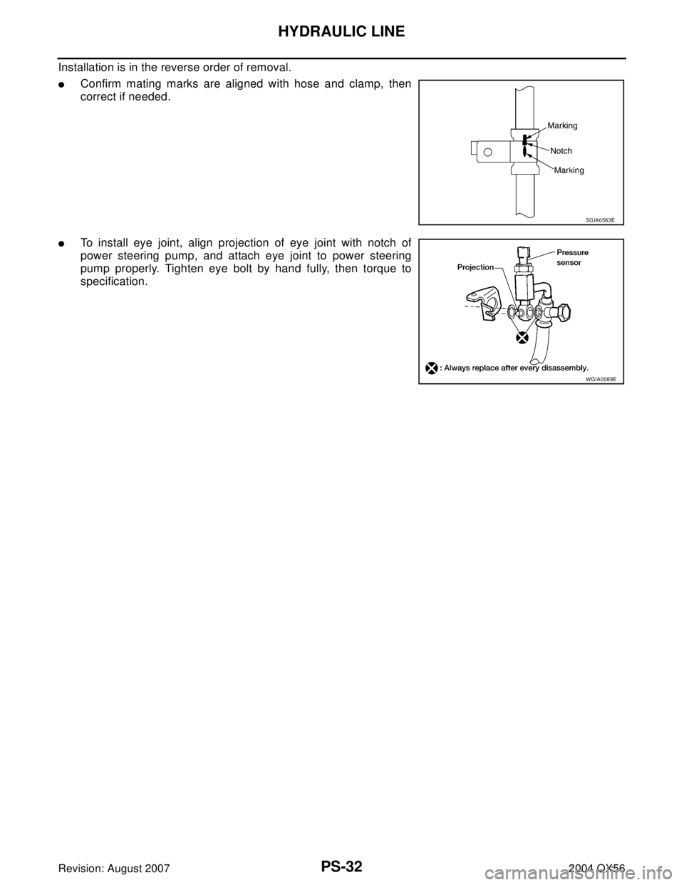
Installation is in the reverse order of removal.
�Confirm mating marks are aligned with hose and clamp, then
correct if needed.
�To install eye joint, align projection of eye joint with notch of
power steering pump, and attach eye joint to power steering
pump properly. Tighten eye bolt by hand fully, then torque to
specification.
SGIA0563E
WGIA0089E
Page 2793 of 3371

RAX-6
WHEEL HUB
Revision: August 20072004 QX56
4. Remove the cotter pin, then remove the nut from the drive shaft
using power tool.
�Discard the cotter pin, use a new one for installation.
5. Remove the drive shaft. Refer to RAX-7, "
Removal and Installa-
tion" .
6. Remove the four wheel hub and bearing assembly bolts using power tool.
�Discard the four wheel hub and bearing assembly bolts, use new ones for installation.
7. Pull out the wheel hub and bearing assembly for access to
remove the rear ABS sensor from the wheel hub and bearing
assembly as shown.
�Inspect the ABS sensor O-ring, replace the ABS sensor
assembly if damaged.
�Clean the ABS sensor hole and mounting surface with a suit-
able brake cleaner and a clean lint-free shop rag. Be careful
that dirt and debris do not enter the axle bearing area.
�Apply a coat of suitable grease to the ABS sensor O-ring and
mounting hole.
CAUTION:
Do not pull on the ABS harness.
8. Remove the wheel hub and bearing assembly.
INSTALLATION
Installation is in the reverse order of removal.
�Apply grease 44003 7S000CM to contact surface (A) between
wheel hub and bearing assembly and drive shaft as shown. Use
sufficient grease to completely coat contact area.
�Inspect the ABS sensor O-ring, replace the ABS sensor assem-
bly if damaged.
�Clean the ABS sensor hole and mounting surface with a suitable
brake cleaner and a clean lint-free shop rag. Be careful that dirt
and debris do not enter the axle bearing area.
�Apply a coat of suitable grease to the ABS sensor O-ring and
mounting hole.
�Use a new cotter pin for installation.
�Use new wheel hub and bearing assembly bolts for installation.
LDIA0050E
LDIA0052E
WDIA0299E
Page 2795 of 3371

RAX-8
REAR DRIVE SHAFT
Revision: August 20072004 QX56
5. Separate the drive shaft from the wheel hub and bearing assembly by lightly tapping the end with a suit-
able hammer and wood block. If it is difficult to separate, use a suitable puller.
6. Remove the drive shaft.
CAUTION:
When removing the drive shaft, do not bend at an excessive angle to the drive shaft joint. Do not
excessively extend the slide joint.
INSPECTION AFTER REMOVAL
�Move the joint up and down, left and right, and in the axial direc-
tion. Check for any rough movement or significant looseness.
�Check the boot for cracks or other damage, and for any grease
leakage.
�If necessary, disassemble the drive shaft, and repair as neces-
sary.
INSTALLATION
Installation is in the reverse order of removal.
�Apply grease 44003 7S000CM to contact surface (A) between
wheel hub and bearing assembly and drive shaft as shown. Use
sufficient grease to completely coat contact area.
�Do not reuse the drive shaft inside flange bolts, discard after
removal and use new drive shaft bolts for installation.
�Do not reuse cotter pin, discard after removal and use a new
cotter pin for installation.
Disassembly and AssemblyEDS001AW
RAA0030D
WDIA0299E
1. Plug 2. Housing 3. Snap ring
4. Ball cage, steel ball, liner race assembly 5. Stopper ring 6. Boot band
7. Boot 8. Shaft 9. Circlip
10. Joint sub-assembly
WDIA0221E
Page 2828 of 3371

SUNROOF
RF-27
C
D
E
F
G
H
J
K
L
MA
B
RF
Revision: August 20072004 QX56
WIND DEFLECTOR
Removal and Installation
1. Open the sunroof.
2. Remove screws from the left, center, and right side wind deflec-
tor holders.
3. Remove the wind deflector from the sunroof frame assembly.
Installation is in the reverse order of removal.
SUNSHADE
Removal and Installation
1. Remove the sunroof frame assembly. Refer to RF-26, "SUNROOF UNIT" .
2. Remove the sunshade stoppers (2 points) from the rear end of
the sunroof frame assembly.
3. Remove the sunshade assembly from the rear end of the sun-
roof frame assembly.
Installation is in the reverse order of removal.
SUNROOF MOTOR
Removal
CAUTION:
�When removing the sunroof motor, be sure that the sunroof is in the fully closed position.
�Never run the removed motor as a single unit.
1. Position the sunroof assembly in the fully closed position.
2. Remove the front roof console assembly. Refer to EI-37, "
HEADLINING" .
3. Disconnect the harness connector from the sunroof motor
assembly.
4. Remove the mounting screws and the sunroof motor assembly.
Installation
CAUTION:
Before installing the sunroof motor assembly, be sure to place the link and wire assembly in the sym-
metrical and fully closed position.
LIIA1099E
SBT 2 51 A
LIIA0270E
Page 2842 of 3371
REAR FINAL DRIVE ASSEMBLY
RFD-11
C
E
F
G
H
I
J
K
L
MA
B
RFD
Revision: August 20072004 QX56
INSTALLATION
Installation is in the reverse order of removal.
CAUTION:
After installation, check the final drive oil level. Refer to MA-24, "
Checking Final Drive Oil" .
ComponentsEDS002JN
R230 2–PINION
WDIA0294E
1. Drive pinion nut 2. Companion flange 3. Front oil seal
4. Pinion front bearing 5. Pinion bearing adjusting spacer (col-
lapsible spacer)6. Pinion rear bearing
7. Pinion height adjusting washer 8. Drive pinion 9. Gear carrier
10. Drive gear 11. Pinion mate shaft 12. Lock pin
13. Pinion mate gear 14. Pinion mate thrust washer 15. Side gear
16. Side gear thrust washer 17. Differential case 18. Side bearing
Page 2892 of 3371
REAR SUSPENSION MEMBER
RSU-33
C
D
F
G
H
I
J
K
L
MA
B
RSU
Revision: August 20072004 QX56
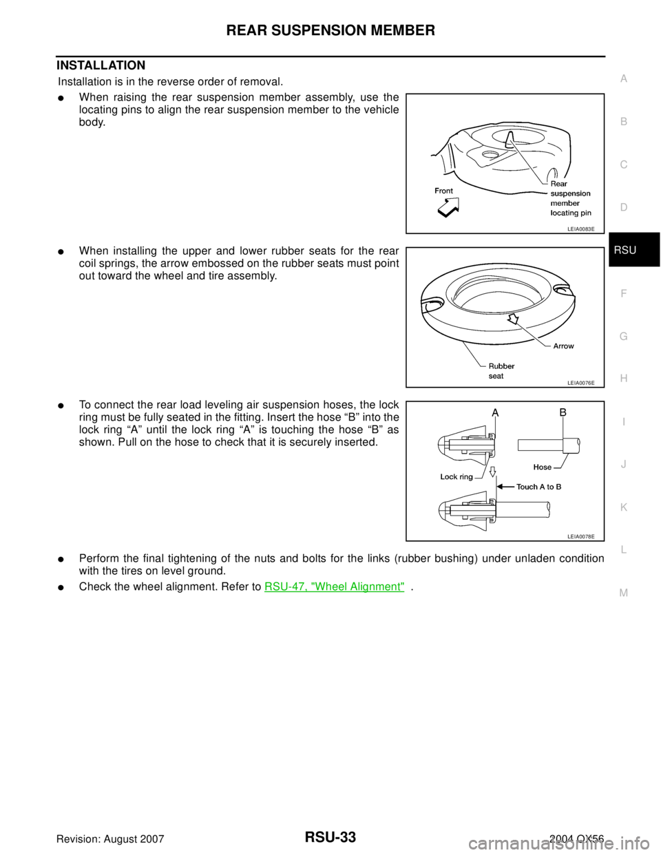
INSTALLATION
Installation is in the reverse order of removal.
�When raising the rear suspension member assembly, use the
locating pins to align the rear suspension member to the vehicle
body.
�When installing the upper and lower rubber seats for the rear
coil springs, the arrow embossed on the rubber seats must point
out toward the wheel and tire assembly.
�To connect the rear load leveling air suspension hoses, the lock
ring must be fully seated in the fitting. Insert the hose “B” into the
lock ring “A” until the lock ring “A” is touching the hose “B” as
shown. Pull on the hose to check that it is securely inserted.
�Perform the final tightening of the nuts and bolts for the links (rubber bushing) under unladen condition
with the tires on level ground.
�Check the wheel alignment. Refer to RSU-47, "Wheel Alignment" .
LEIA0083E
LEIA0076E
LEIA0078E
Page 2893 of 3371

RSU-34
SHOCK ABSORBER
Revision: August 20072004 QX56
SHOCK ABSORBERPFP:56210
Removal and Installation EES0011J
REMOVAL
1. Remove the wheel and tire assembly using power tool. Refer to WT-6, "Rotation" .
2. Use CONSULT-II “EXHAUST SOLENOID” active test to release the air pressure from the rear load level-
ing air suspension system.
3. Remove the four clips and remove the rear fender protector, front.
4. Disconnect the rear load leveling air suspension hose from the
shock absorber.
�To disconnect the hose, push in on the lock ring using a suit-
able tool and pull the air hose out.
5. Remove the shock absorber upper and lower end bolts using
power tool.
6. Remove the shock absorber.
CAUTION:
Do not damage the rubber boot on the shock absorber.
INSTALLATION
Installation is in the reverse order of removal.
�Tighten the shock absorber bolts to specification. Refer to RSU-25, "Components" .
INSPECTION AFTER INSTALLATION
�Check the shock absorber for any air leaks or damage to the rubber boot.
�Check the shock absorber for smooth operation through a full stroke, both compression and extension.
�Check piston rod for cracks, deformation or other damage and replace if necessary.
LEIA0081E
LEIA0082E