Page 2912 of 3371
SEAT BELTS
SB-5
C
D
E
F
G
I
J
K
L
MA
B
SB
Revision: August 20072004 QX56
REMOVAL OF SEAT BELT BUCKLE
1. Remove the front seat. Refer to SE-96, "Components" .
2. Remove the seat cushion. Refer to SE-101, "
SEAT CUSHION TRIM AND PAD" .
3. Remove screw and seat cushion inner finisher.
4. Remove the anchor bolt and buckle.
INSTALLATION OF SEAT BELT BUCKLE
Installation is in the reverse order of removal.
WHIA0238E
Page 2914 of 3371

SEAT BELTS
SB-7
C
D
E
F
G
I
J
K
L
MA
B
SB
Revision: August 20072004 QX56
4. Remove the seat belt guide bolt.
5. Remove seat belt retractor anchor bolt and the seat belt retractor and belt assembly.
6. Remove the seat belt height adjustor assembly.
INSTALLATION
Installation is in the reverse order of removal.
�Ensure that seat belt height adjuster is locked in the lowest position during installation.
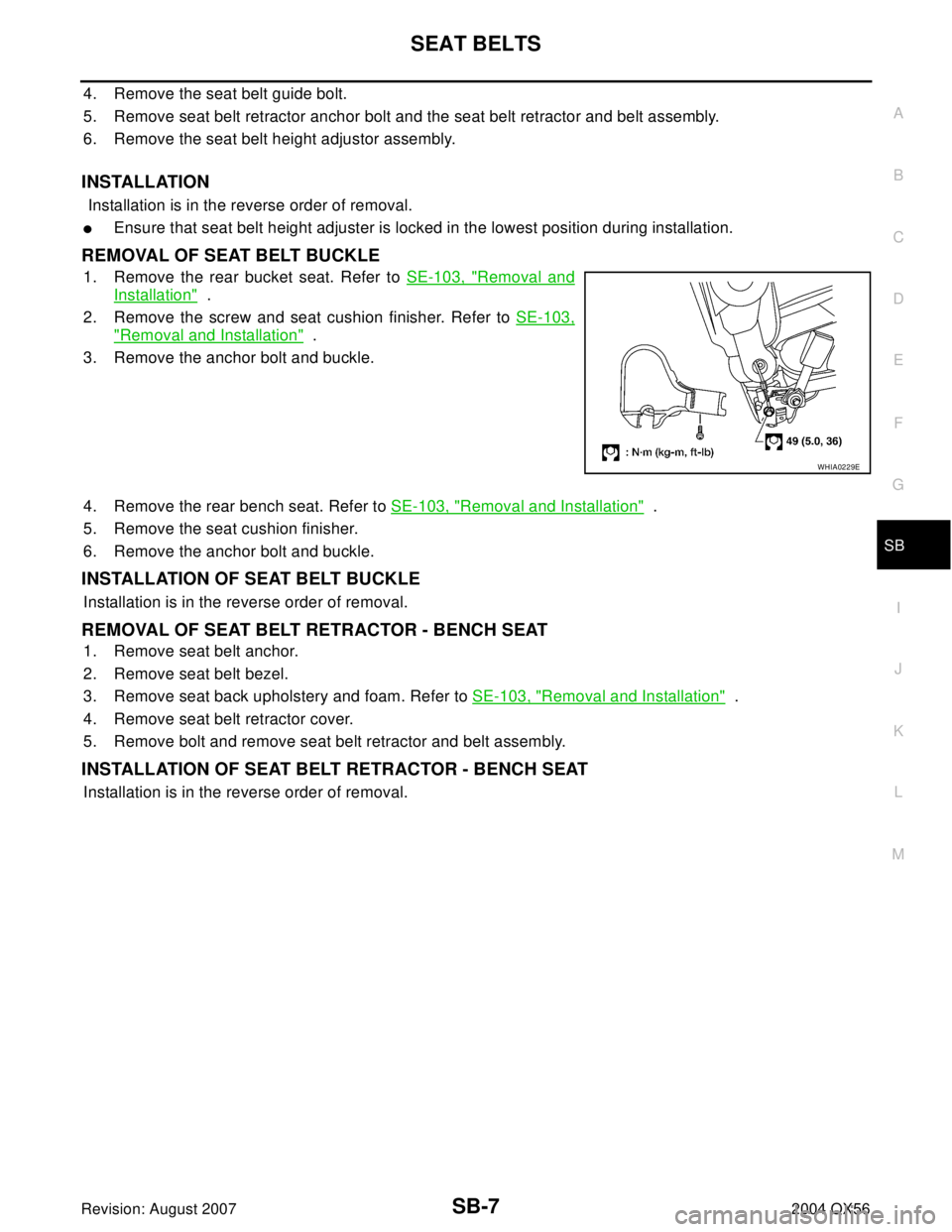
REMOVAL OF SEAT BELT BUCKLE
1. Remove the rear bucket seat. Refer to SE-103, "Removal and
Installation" .
2. Remove the screw and seat cushion finisher. Refer to SE-103,
"Removal and Installation" .
3. Remove the anchor bolt and buckle.
4. Remove the rear bench seat. Refer to SE-103, "
Removal and Installation" .
5. Remove the seat cushion finisher.
6. Remove the anchor bolt and buckle.
INSTALLATION OF SEAT BELT BUCKLE
Installation is in the reverse order of removal.
REMOVAL OF SEAT BELT RETRACTOR - BENCH SEAT
1. Remove seat belt anchor.
2. Remove seat belt bezel.
3. Remove seat back upholstery and foam. Refer to SE-103, "
Removal and Installation" .
4. Remove seat belt retractor cover.
5. Remove bolt and remove seat belt retractor and belt assembly.
INSTALLATION OF SEAT BELT RETRACTOR - BENCH SEAT
Installation is in the reverse order of removal.
WHIA0229E
Page 2916 of 3371
SEAT BELTS
SB-9
C
D
E
F
G
I
J
K
L
MA
B
SB
Revision: August 20072004 QX56
5. Remove the seat belt retractor anchor nut, RH side, and seat belt retractor and belt assembly.
6. Remove seat belt buckle anchor bolt from seat belt anchor base and remove seat belt buckles.
INSTALLATION
Installation is in the reverse order of removal.
�Ensure that seat belt height adjuster is locked in the lowest position during installation.
�Seat belt anchor base should be flat to the floor during installation and not on the anti-rotation bead.
Third Row Center EHS000VU
REMOVAL AND INSTALLATION
REMOVAL
1. Remove the rear roof finisher. Refer to EI-37, "HEADLINING" .
2. Lower the rear portion of the headliner.
3. Remove the seat belt retractor anchor bolts and seat belt retractor and belt assembly.
INSTALLATION
Installation is in the reverse order of removal.
WHIA0230E
Page 2921 of 3371
SB-14
TOP TETHER STRAP CHILD RESTRAINT
Revision: August 20072004 QX56
TOP TETHER STRAP CHILD RESTRAINTPFP:88000
Removal and InstallationEHS000VX
1. Remove luggage room rear lower finisher. Refer to EI-39, "LUG-
GAGE FLOOR TRIM" .
2. Remove bolt and remove tether anchor from the luggage box
bracket.
Installation is in the reverse order of removal.
WHIA0234E
Page 2930 of 3371
BATTERY
SC-9
C
D
E
F
G
H
I
J
L
MA
B
SC
Revision: August 20072004 QX56
Removal and Installation EKS00797
REMOVAL
1. Disconnect the negative battery terminal and positive battery
terminal.
CAUTION:
When removing, remove negative battery terminal first.
2. Remove the battery cover.
3. Remove the battery clamp bolt and battery clamp.
4. Remove the battery.
INSTALLATION
Installation is in the reverse order of removal.
CAUTION:
When installing, install positive battery terminal first.
WKIA1385E
Battery clamp bolt : 14.7 N·m (1.5 kg-m, 11 ft-lb)
Battery terminal nut : 3.5 N·m (0.36 kg-m, 31 in-lb)
Page 2937 of 3371
SC-16
STARTING SYSTEM
Revision: August 20072004 QX56
MINIMUM SPECIFICATION OF CRANKING VOLTAGE REFERENCING COOLANT TEMPERA-
TURE
Removal and InstallationEKS0079B
REMOVAL
1. Remove the intake manifold. Refer to EM-15, "Removal and Installation" .
2. Disconnect the starter harness connectors.
3. Remove the two starter bolts, using power tools.
4. Remove the starter.
INSTALLATION
Installation is in the reverse order of removal.
CAUTION:
Tighten terminal "2" nut carefully.
Engine coolant temperature Voltage V
−30°C to −20°C (−22°F to −4°F) 8.4
−19°C to −10°C (−2°F to 14°F) 8.9
−9°C to 0°C (16°F to 32°F) 9.3
More than 1°C (More than 34°F) 9.7
WKIA1388E
Terminal "2"nut : 10.8 N·m (1.1 kg-m, 8 ft-lb)
Page 2948 of 3371
CHARGING SYSTEM
SC-27
C
D
E
F
G
H
I
J
L
MA
B
SC
Revision: August 20072004 QX56
MALFUNCTION INDICATOR
The IC regulator warning function activates to illuminate “CHARGE” warning lamp, if any of the following
symptoms occur while generator is operating:
�Excessive voltage is produced.
�No voltage is produced.
Removal and InstallationEKS0079H
REMOVAL
1. Disconnect the negative battery terminal.
2. Remove the fan shroud. Refer to CO-10, "
Removal and Installation" .
3. Remove the drive belt. Refer to EM-12, "
Removal and Installation" .
4. Remove the lower bracket, using power tools.
5. Remove the generator upper bolt, using power tools.
6. Disconnect the generator harness connectors.
7. Remove the generator.
INSTALLATION
Installation is in the reverse order of removal.
�Install the generator and check the tension of the drive belt. Refer to EM-12, "Tension Adjustment" .
CAUTION:
Tighten terminal "1" nut carefully.
WKIA1390E
Terminal "1" nut : 10.8 N·m (1.1 kg-m, 8 ft-lb)
Page 3048 of 3371

FRONT SEAT
SE-99
C
D
E
F
G
H
J
K
L
MA
B
SE
Revision: August 20072004 QX56
Removal and InstallationEIS007N5
REMOVAL
NOTE:
When removing or installing the seat trim, handle it carefully to keep dirt out and avoid damage.
CAUTION:
�Before removing the front seat, turn the ignition switch off, disconnect both battery cables and
wait at least 3 minutes.
�When checking the power seat circuit for continuity using a circuit tester, do not confuse its con-
nector with the side air bag module connector. Such an error may cause the air bag to deploy.
�Do not drop, tilt, or bump the side air bag module while installing the seat. Always handle it with
care.
�After front side air bag module inflates, front seatback assembly must be replaced.
�Front passenger seat is equipped with an Occupant Classification System sensor and control
module. Do not disassemble front passenger seat cushion assembly or remove the trim as this
will affect the Occupant Classification System calibration.
�Always replace passenger seat cushion as an assembly.
1. Slide the seat until the four body mounting bolts are visible and a tool can be inserted.
NOTE:
�If disassembling the seat after removal, set the front/rear cushion lifters to the top position.
2. Disconnect both battery cables and wait at least 3 minutes.
3. Disconnect the side air bag module harness connector.
4. Remove the four body mounting bolts.
5. Disconnect the power seat harness connectors and remove the seat from the vehicle.
NOTE:
When removing and installing the seat, use shop cloths to protect the vehicle from damage.
INSTALLATION
�Installation is in the reverse order of removal.
Disassembly and AssemblyEIS002ZJ
SEATBACK TRIM AND PAD
Disassembly
NOTE:
Only complete seatback assemblies can be replaced on vehicles equipped with side air bags.
NOTE:
Be sure to set the front/rear cushion lifter to the top position.
Driver Seat
1. Remove the headrest.
7. Outboard reclining arm outer cover 8. Outboard reclining arm inner cover 9. Inboard reclining arm inner cove
10. Latch cover 11. LH outer leg cover 12. Outboard reclining arm inner cover
13. Seat cushion inner cover 14. Passenger seat wiring harness 15. Inner front leg cover
16. Power seat frame assembly 17. NVH assembly 18. Seat cushion front finisher
19. Outer pedestal finisher 20. Seat cushion outer finisher 21. Seat cushion assembly
22. Power seat switch escutcheon 23. Slide switch knob 24. Recliner switch knob
25. Seatback assembly 26. Headrest holder 27. Seat slide/ recline switch
28. Power lumbar switch