Page 2259 of 3371
IP-14
INSTRUMENT PANEL ASSEMBLY
Revision: August 20072004 QX56
Instrument Lower Cover RH and Glove Box
1. Remove screws using power tool, release clips and remove
lower instrument panel RH and glove box as an assembly.
2. Remove damper clip from glove box.
3. Remove glove box pins and glove box.
4. Using power tool, remove screws and glove box striker.
5. Remove fuse block cover.
6. Remove screws and remove glove box damper.
Installation
Installation is in the reverse order of removal
1. Glove box damper 2. Lower instrument panel RH 3. Clips
4. Glove box pins 5. Glove box 6. Glove box striker
7. Fuse block cover 8. Glove box assembly
WIIA0666E
LLIA0072E
Page 2261 of 3371

IP-16
INSTRUMENT PANEL ASSEMBLY
Revision: August 20072004 QX56
1. Remove instrument lower cover RH. Refer to IP-10, "INSTRUMENT PANEL ASSEMBLY" .
2. Remove glove box assembly. Refer to IP-14, "
Instrument Lower Cover RH and Glove Box" .
3. Remove instrument lower cover LH. Refer to IP-10, "
INSTRUMENT PANEL ASSEMBLY" .
4. Remove shift knob and A/T console finisher. Refer to IP-13, "
A/T Finisher" .
�Remove cup holder insert.
�Remove shift indicator.
5. Remove cluster lid D. Refer to IP-12, "
Cluster Lid D" .
6. Disconnect shift cable and electrical harness from shifter.
7. Remove shifter.
8. Remove screws from center console.
�Disconnect electrical harnesses.
9. Move front seats forward and remove center console assembly in a rearward direction.
10. Remove tray and mat from console bin.
11. Remove latch from console lid.
12. Remove hinge from console lid. Remove console lid.
�Remove console lid mat.
13. Remove console bin.
�Disconnect electrical harness from DVD player, if equipped.
�Remove hinge from console bin.
14. Remove rear upper finisher.
15. Remove rear cup holder assembly.
16. Remove upper side finishers LH/RH.
17. Remove screws on each side, disconnect clips and remove console covers LH/RH.
18. Remove rear finisher assembly.
�Disconnect electrical connectors.
19. Remove power point assembly.
20. Remove mask and storage compartment.
21. Remove console front bracket.
22. Remove heat duct and console rear duct.
23. Remove console rear bracket.
Assembly is in the reverse order of disassembly.
1. Console lid assembly 2. A/T finisher 3. Tray
4. Storage compartment 5. Storage compartment mask 6. Console reinforcement assembly
7. Console front bracket 8. Upper side finisher LH 9. Instrument lower cover LH
10. Console cover LH 11. Rear console duct 12. Power point assembly
13. Rear cup holder assembly 14. Rear finisher assembly 15. Console rear bracket
16. Heat duct 17. Rear upper finisher 18. Console bin mat
19. Console bin 20. Console cover RH 21. Instrument lower cover RH
22. Upper side finisher RH 23. A/T transmission control 24 Mask
25 Cup holder insert
Page 2263 of 3371
IP-18
INSTRUMENT PANEL ASSEMBLY
Revision: August 20072004 QX56
1. Remove cup holder insert.
2. Release latch and remove rear console assembly.
3. Remove hinge cover.
4. Remove screws from hinge assembly and remove console lid assembly.
�Remove hinge from upper console assembly.
�Remove latch from lid assembly.
5. Remove screws and separate upper and lower console assemblies.
�Remove floor latch from upper console assembly.
6. Remove screws and remove bin from upper console assembly.
7. Remove screws and remove floor base.
8. Remove bolts and remove floor bracket.
Assembly is in the reverse order of disassembly.
Page 2463 of 3371

LT-32
HEADLAMP (FOR USA)
Revision: August 20072004 QX56
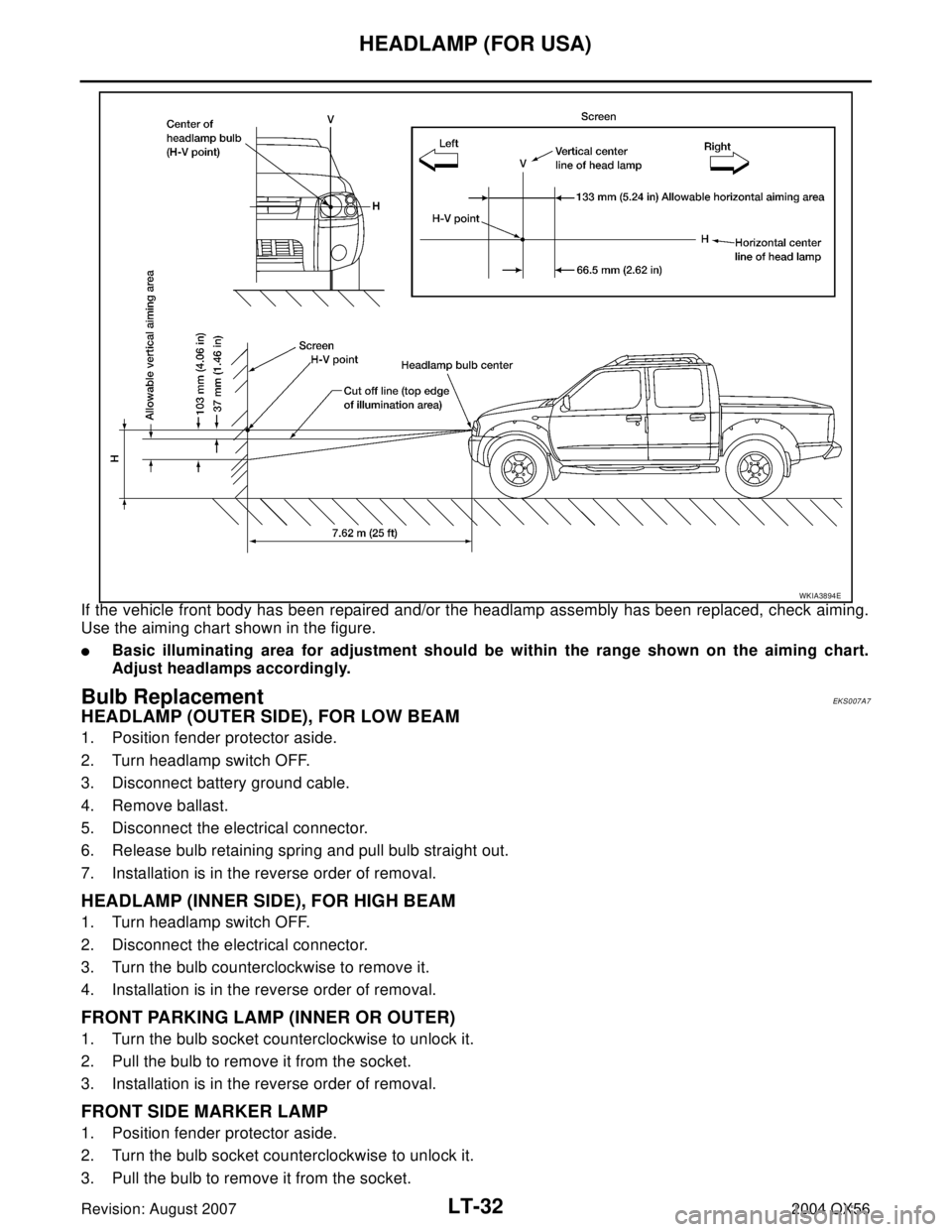
If the vehicle front body has been repaired and/or the headlamp assembly has been replaced, check aiming.
Use the aiming chart shown in the figure.
�Basic illuminating area for adjustment should be within the range shown on the aiming chart.
Adjust headlamps accordingly.
Bulb Replacement EKS007A7
HEADLAMP (OUTER SIDE), FOR LOW BEAM
1. Position fender protector aside.
2. Turn headlamp switch OFF.
3. Disconnect battery ground cable.
4. Remove ballast.
5. Disconnect the electrical connector.
6. Release bulb retaining spring and pull bulb straight out.
7. Installation is in the reverse order of removal.
HEADLAMP (INNER SIDE), FOR HIGH BEAM
1. Turn headlamp switch OFF.
2. Disconnect the electrical connector.
3. Turn the bulb counterclockwise to remove it.
4. Installation is in the reverse order of removal.
FRONT PARKING LAMP (INNER OR OUTER)
1. Turn the bulb socket counterclockwise to unlock it.
2. Pull the bulb to remove it from the socket.
3. Installation is in the reverse order of removal.
FRONT SIDE MARKER LAMP
1. Position fender protector aside.
2. Turn the bulb socket counterclockwise to unlock it.
3. Pull the bulb to remove it from the socket.
WKIA3894E
Page 2464 of 3371

HEADLAMP (FOR USA)
LT-33
C
D
E
F
G
H
I
J
L
MA
B
LT
Revision: August 20072004 QX56
4. Installation is in the reverse order of removal.
CAUTION:
�After installing the bulb, be sure to install the bulb socket securely to ensure watertightness.
�Do not touch the glass of bulb directly by hand. Keep grease and other oily substances away from
it. Do not touch bulb by hand while it is lit or right after being turned off. Burning may result.
�Do not leave bulb out of headlamp assembly for a long time because dust, moisture, smoke, etc.
may affect the performance of the lamp. When replacing bulb, be sure to replace it with a new one.
Removal and InstallationEKS007A8
REMOVAL
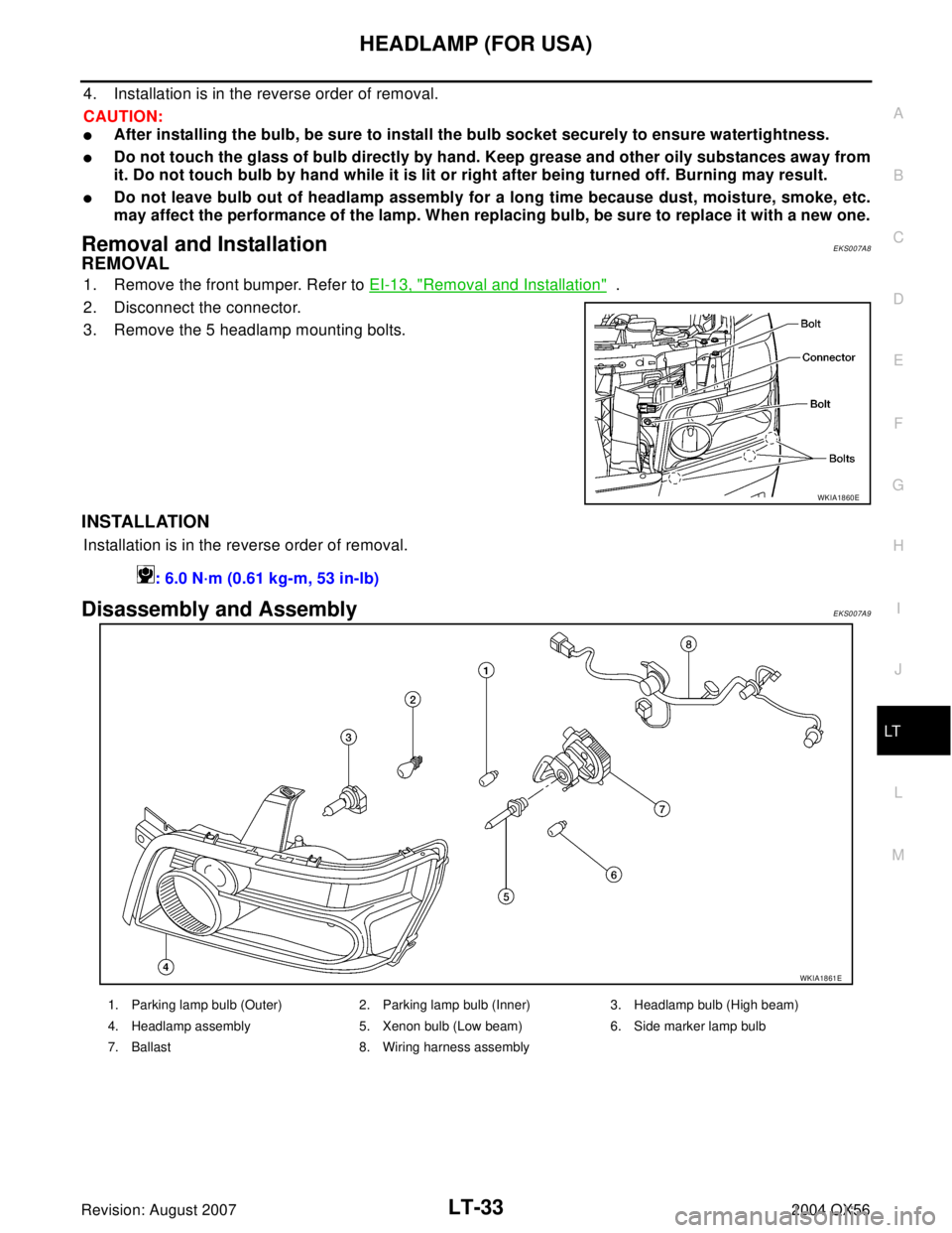
1. Remove the front bumper. Refer to EI-13, "Removal and Installation" .
2. Disconnect the connector.
3. Remove the 5 headlamp mounting bolts.
INSTALLATION
Installation is in the reverse order of removal.
Disassembly and AssemblyEKS007A9
WKIA1860E
: 6.0 N·m (0.61 kg-m, 53 in-lb)
WKIA1861E
1. Parking lamp bulb (Outer) 2. Parking lamp bulb (Inner) 3. Headlamp bulb (High beam)
4. Headlamp assembly 5. Xenon bulb (Low beam) 6. Side marker lamp bulb
7. Ballast 8. Wiring harness assembly
Page 2495 of 3371
LT-64
AUTO LIGHT SYSTEM
Revision: August 20072004 QX56
Removal and Installation of Optical SensorEKS007B3
REMOVAL
1. Remove defrost grille. Refer to IP-10, "INSTRUMENT PANEL ASSEMBLY" .
2. Disconnect the connector.
3. Turn the optical sensor counterclockwise to remove it from
defroster grille.
INSTALLATION
Installation is in the reverse order of removal.
WKIA1061E
Page 2510 of 3371

FRONT FOG LAMP
LT-79
C
D
E
F
G
H
I
J
L
MA
B
LT
Revision: August 20072004 QX56
Bulb Replacement EKS007BG
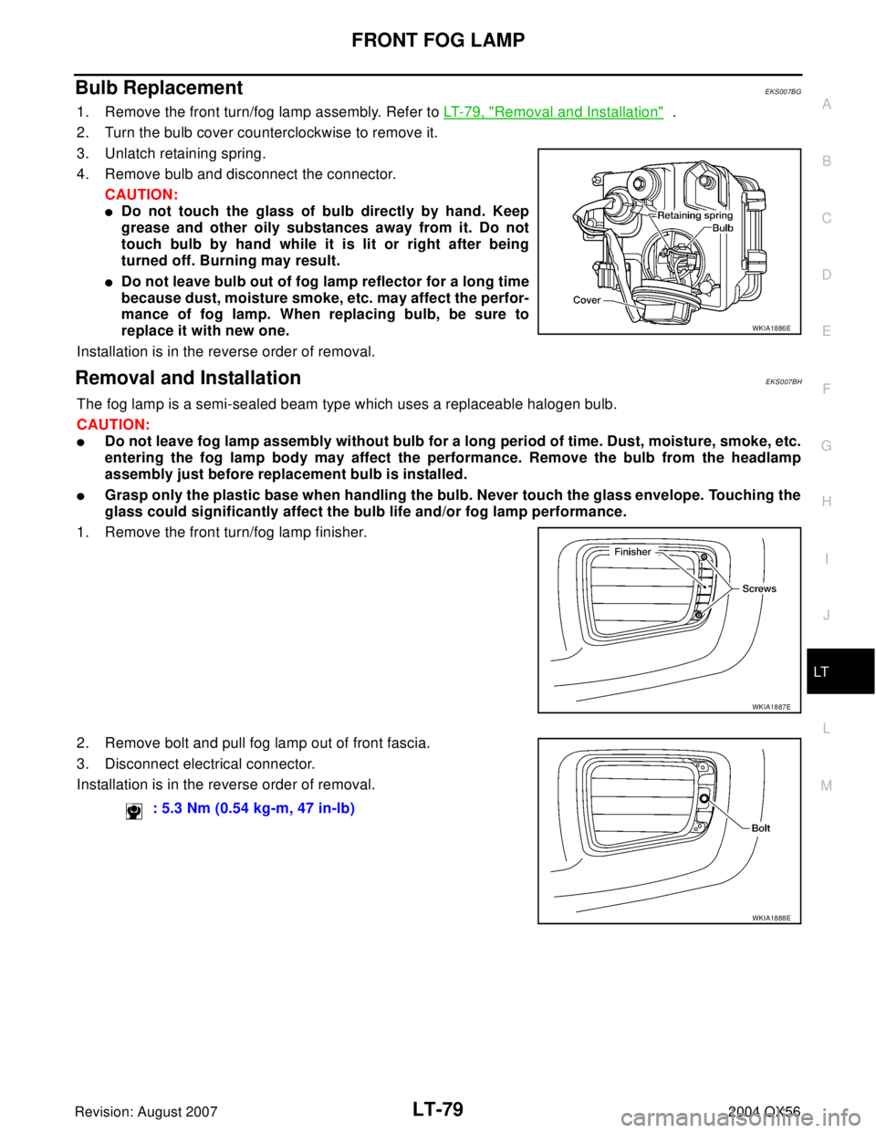
1. Remove the front turn/fog lamp assembly. Refer to LT-79, "Removal and Installation" .
2. Turn the bulb cover counterclockwise to remove it.
3. Unlatch retaining spring.
4. Remove bulb and disconnect the connector.
CAUTION:
�Do not touch the glass of bulb directly by hand. Keep
grease and other oily substances away from it. Do not
touch bulb by hand while it is lit or right after being
turned off. Burning may result.
�Do not leave bulb out of fog lamp reflector for a long time
because dust, moisture smoke, etc. may affect the perfor-
mance of fog lamp. When replacing bulb, be sure to
replace it with new one.
Installation is in the reverse order of removal.
Removal and InstallationEKS007BH
The fog lamp is a semi-sealed beam type which uses a replaceable halogen bulb.
CAUTION:
�Do not leave fog lamp assembly without bulb for a long period of time. Dust, moisture, smoke, etc.
entering the fog lamp body may affect the performance. Remove the bulb from the headlamp
assembly just before replacement bulb is installed.
�Grasp only the plastic base when handling the bulb. Never touch the glass envelope. Touching the
glass could significantly affect the bulb life and/or fog lamp performance.
1. Remove the front turn/fog lamp finisher.
2. Remove bolt and pull fog lamp out of front fascia.
3. Disconnect electrical connector.
Installation is in the reverse order of removal.
WKIA1886E
WKIA1887E
: 5.3 Nm (0.54 kg-m, 47 in-lb)
WKIA1888E
Page 2525 of 3371
LT-94
TURN SIGNAL AND HAZARD WARNING LAMPS
Revision: August 20072004 QX56
Bulb Replacement (Front Turn Signal Lamp)EKS007BU
1. Remove turn/fog lamp assembly. Refer to LT- 7 9 , "Removal and Installation" .
2. Turn bulb socket counterclockwise to remove it from lamp housing.
3. Pull bulb from socket.
Installation is in the reverse order of removal.
Bulb Replacement (Rear Turn Signal Lamp)EKS007BV
Refer to LT- 1 2 2 , "Bulb Replacement (Turn Signal)" in REAR COMBINATION LAMP.
Removal and Installation of Front Turn Signal LampEKS007BW
Refer to LT- 3 3 , "Removal and Installation" .
Removal and Installation of Rear Turn Signal Lamp EKS007BX
Refer to LT- 1 2 2 , "Removal and Installation" in REAR COMBINATION LAMP.