Page 1954 of 3371

ENGINE ASSEMBLY
EM-71
C
D
E
F
G
H
I
J
K
L
MA
EM
Revision: August 20072004 QX56
5. Remove the cowl extension. Refer to EI-18, "Removal and Installation" .
6. Remove engine room cover using power tools.
7. Remove the air duct and air cleaner case assembly. Refer to EM-14, "
REMOVAL" .
8. Disconnect vacuum hose between vehicle and engine and set it aside.
9. Remove the radiator assembly and hoses. Refer to CO-10, "
REMOVAL" .
10. Remove the drive belts. Refer to EM-12, "
Removal" .
11. Remove the fan blade. Refer to CO-13, "
REMOVAL" .
12. Disconnect the engine room harness from the fuse box and set it aside for easier work.
13. Disconnect the ECM.
14. Disconnect the engine room harness from the engine side and set it aside for easier work.
15. Disconnect the engine harness grounds.
16. Disconnect the reservoir tank for power steering from engine and move it aside for easier work.
17. Disconnect power steering oil pump from engine. Move it from its location and secure with a rope for eas-
ier work. Refer to PS-26, "
REMOVAL" .
18. Remove the A/C compressor bolts and set aside. Refer to ATC-166, "
REMOVAL" .
19. Disconnect brake booster vacuum line.
20. Disconnect EVAP line.
21. Disconnect the fuel hose at the engine side connection. Refer to EM-29, "
REMOVAL" .
22. Disconnect the heater hoses at cowl, and install plugs to avoid leakage of engine coolant.
23. Remove the A/T oil level indicator and indicator tube upper bolts.
24. Remove the A/T. Refer to AT-255, "
Removal and Installation (4x2)" , or AT-258, "Removal and Installation
(4x4)" .
25. Install engine slingers into left bank cylinder head and right bank
cylinder head.
26. Lift with hoist and secure the engine in position.
27. Remove engine assembly from vehicle, avoiding interference
with vehicle body.
CAUTION:
�Before and during this lifting, always check if any har-
nesses are left connected.
28. Remove alternator. Refer to SC-27, "
REMOVAL" .
29. Remove engine mounting insulator and bracket using power tool.
INSTALLATION
Installation is in the reverse order of removal.
CAUTION:
�When replacing an engine or transmission you must make sure the dowels are installed correctly
during re-assembly.
�Improper alignment caused by missing dowels may cause vibration, oil leaks or breakage of driv-
etrain components.
WBIA0464E
Engine slinger torque: 45.0 N·m (4.6 kg-m, 33 ft-lb)
PBIC1556E
Page 1964 of 3371

CYLINDER BLOCK
EM-81
C
D
E
F
G
H
I
J
K
L
MA
EM
Revision: August 20072004 QX56
14. Install the connecting rod cap.
�Match the stamped cylinder number marks on the connecting
rod with those on the cylinder cap to install.
15. Tighten the connecting rod bolts using Tool.
�Apply engine oil to the threads and seats of the connecting
rod bolts.
�After tightening the bolts, make sure that the crankshaft
rotates smoothly.
�Check the connecting rod side clearance. Refer to EM-89, "CONNECTING ROD SIDE CLEARANCE"
16. Install knock sensor.
CAUTION:
If the knock sensor is dropped, replace it with a new one.
�Make sure that there is no foreign material on the cylinder
block mating surface and the back surface of the knock sen-
sor.
�Install it with its connector facing the center of cylinder block
side.
�Do not tighten the knock sensor bolts while holding the con-
nector.
�Make sure that the knock sensor does not interfere with other
parts.
�Position sub-harness as shown before installing intake mani-
fold.
17. Installation of the remaining components is in the reverse order of removal.
18. Remove engine assembly from engine stand.
KBIA2536E
Tool number : KV10112100 (BT-8653-A)
Connecting rod bolts
Step 1 : 19.6 N·m (1.5 kg-m, 11 ft-lb)
Step 2 : 90° clockwise
WBIA0586E
KBIA2493E
KBIA2549E
Page 1997 of 3371

EX-4Revision: August 2007
EXHAUST SYSTEM
2004 QX56
REMOVAL
Remove exhaust system components using power tool.
INSTALLATION
Installation is in the reverse order of removal.
CAUTION:
�Always replace exhaust gaskets with new ones when reassembling.
�Before installing a new heated oxygen sensor, clean and lube the exhaust tube threads using tool.
�Discard any heated oxygen sensor which has been dropped from a height of more than 0.5 m (19.7
in) onto a hard surface such as a concrete floor; install a new one.
�Do not over-torque the heated oxygen sensor. Doing so may damage the heated oxygen sensor,
resulting in the MIL coming on.
�If any mounting insulator is badly deformed, repair or replace it. If deposits such as mud pile up on
the mounting insulators, clean and inspect them.
�Temporarily tighten the mounting nuts on the exhaust manifold side and the mounting bolts on the
vehicle side. Check each part for interference with other components, and then tighten the nuts
and bolts to specification.
INSPECTION AFTER INSTALLATION
�With the engine running, check exhaust tube joints for gas leakage and unusual noises.
�Check to ensure that mounting brackets and mounting rubbers are installed properly and free from undue
stress. Improper installation could result in excessive noise and vibration. Tool number
A : — (J-43897-18)
B : — (J-43897-12)
Page 2003 of 3371

FAX-6
WHEEL HUB
Revision: August 20072004 QX56
4. Put alignment mark on disc rotor and wheel hub and bearing
assembly, then remove disc rotor.
5. Remove cotter pin, then remove lock nut from drive shaft using power tool. Refer to FA X -7 , "
Removal and
Installation" .
6. Remove drive shaft from wheel hub and bearing assembly. Refer to FAX-7, "
Removal and Installation" .
7. Remove wheel sensor. Refer to BRC-64, "
Removal and Installation" .
�Inspect the wheel sensor O-ring, replace the wheel sensor assembly if damaged.
�Clean the wheel sensor hole and mounting surface with a suitable brake cleaner and clean lint-free
shop rag. Be careful that dirt and debris do not enter the axle bearing area.
�Apply a coat of suitable grease to the wheel sensor O-ring and mounting hole.
CAUTION:
Do not pull on the wheel sensor harness.
8. Remove wheel hub and bearing assembly bolts using power tool.
9. Remove splash guard and wheel hub and bearing assembly from steering knuckle.
INSPECTION AFTER REMOVAL
Check for deformity, cracks and damage on each part, replace if necessary.
INSTALLATION
Installation is in the reverse order of removal.
�Use new bolts when installing the wheel hub and bearing assembly.
�When installing disc rotor on wheel hub and bearing assembly,
position the disc rotor according to alignment mark.
(When not using the alignment mark, refer to BR-22, "
Removal
and Installation of Brake Caliper and Disc Rotor" .)
�When installing wheel and tire. Refer to WT-6, "Rotation" .
WDIA0044E
WDIA0044E
Page 2005 of 3371
FAX-8
DRIVE SHAFT
Revision: August 20072004 QX56
INSTALLATION
Installation is in the reverse order of removal.
�Tighten wheel nuts to specification. Refer to WT-6, "Rotation" .
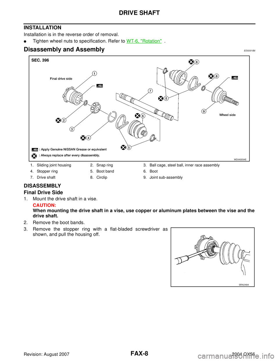
Disassembly and AssemblyEDS001B6
DISASSEMBLY
Final Drive Side
1. Mount the drive shaft in a vise.
CAUTION:
When mounting the drive shaft in a vise, use copper or aluminum plates between the vise and the
drive shaft.
2. Remove the boot bands.
3. Remove the stopper ring with a flat-bladed screwdriver as
shown, and pull the housing off.
1. Sliding joint housing 2. Snap ring 3. Ball cage, steel ball, inner race assembly
4. Stopper ring 5. Boot band 6. Boot
7. Drive shaft 8. Circlip 9. Joint sub-assembly
WDIA0054E
SRA2 49 A
Page 2021 of 3371
FFD-10
SIDE OIL SEALS
Revision: August 20072004 QX56
SIDE OIL SEALSPFP:33142
Removal and InstallationEDS0035K
REMOVAL
1. Remove front final drive. Refer to FFD-12, "REMOVAL" .
2. Remove differential side shaft and side flange using suitable
tool.
3. Place a small hole in seal case, using suitable tool.
4. Install slide hammer tool as shown and remove seal.
5. Installation is in the reverse order of removal.
BDIA0006E
LDIA0129E
LDIA0130E
Page 2026 of 3371

FRONT FINAL DRIVE ASSEMBLY
FFD-15
C
E
F
G
H
I
J
K
L
MA
B
FFD
Revision: August 20072004 QX56
ASSEMBLY INSPECTION AND ADJUSTMENT
�Before inspection and adjustment, drain gear oil.
Total Preload Torque
1. Rotate drive pinion back and forth 2 to 3 times to check for unusual noise and rotation malfunction.
2. Rotate drive pinion at least 20 times to check for smooth operation of the bearing.
3. Measure total preload with preload gauge.
�If measured value is out of the specification, disassemble it to
check and adjust each part. Adjust the pinion bearing preload
and side bearing preload.
Adjust the pinion bearing preload first, then adjust the side bear-
ing preload.
Tooth Contact
1. Remove rear cover. Refer to FFD-11, "REMOVAL" .
2. Thoroughly clean drive gear and drive pinion teeth.
3. Lightly apply a mixture of powdered ferric oxide and oil or the
equivalent. Apply it to 3 or 4 teeth of drive gear drive side.
4. Rotate drive gear back and forth several times, check drive pin-
ion gear to drive gear tooth contact.
CAUTION:
Check tooth contact on drive side and reverse side.
34. Bushing 35. Bearing 36 Screw
37 Dowel pin
Tool number : ST3127S000 (J-25765-A)
Total preload (with oil seal):
2.98 - 4.76 N·m (0.31 - 0.48 kg-m, 27 - 42 in-lb)
SDIA2220E
When the preload torque is large
On pinion bearings: Replace the collapsible spacer.
On side bearings: Loosen the side bearing adjust nuts at the same force on each side.
When the preload is small
On pinion bearings: Tighten the drive pinion nut.
On side bearings: Tighten the side bearing adjust nuts at the same force on each side.
SDIA2248E
SDIA2249E
Page 2053 of 3371

FL-8Revision: August 2007
FUEL LEVEL SENSOR UNIT, FUEL FILTER AND FUEL PUMP ASSEMBLY
2004 QX56
11. Remove the lock ring using Tool.
12. Remove the fuel level sensor, fuel filter, and fuel pump assem-
bly.
CAUTION:
�Do not bend the float arm during removal.
�Avoid impacts such as dropping when handling the com-
ponents.
INSTALLATION
Installation is in the reverse order of removal.
�Connect the quick connector as follows:
–Check the connection for any damage or foreign materials.
–Align the connector with the pipe, then insert the connector straight into the pipe until a click is heard.
–After connecting the quick connector, make sure that the con-
nection is secure by checking as follows:
–Pull the tube and the connector to make sure they are securely
connected.
–Visually inspect the connector to make sure the two retainer tabs
are securely connected.
INSPECTION AFTER INSTALLATION
1. Turn the ignition switch ON but do not start engine, then check the fuel pipes and hose connections for
leaks while applying fuel pressure to the system.
2. Start the engine and rev it above idle speed, then check that there are no fuel leaks at any of the fuel pipe
and hose connections.Tool number : — (J-46536)
LBIA0389E
PBIC1653E