Page 1899 of 3371
.
b. With the sleeve si")
EM-16Revision: August 2007
INTAKE MANIFOLD
2004 QX56
�Perform the following steps to disconnect the quick connector
using Tool.
a. Remove quick connector cap (engine side only).
b. With the sleeve side of Tool facing quick connector, install Tool
onto fuel tube.
c. Insert Tool into quick connector until sleeve contacts and goes
no further. Hold the Tool in that position.
CAUTION:
Inserting the Tool hard will not disconnect quick connector.
Hold Tool where it contacts and goes no further.
d. Draw and pull out quick connector straight from fuel tube.
CAUTION:
�Pull quick connector holding A position in illustration.
�Do not pull with lateral force applied. O-ring inside quick connector may be damaged.
�Prepare container and cloth beforehand as fuel will leak out.
�Avoid fire and sparks.
�Be sure to cover openings of disconnected pipes with plug or plastic bag to avoid fuel leakage
and entry of foreign materials.
6. Remove or disconnect harnesses, brackets, vacuum hose, vacuum gallery and PCV hose and tube from
intake manifold.
7. Remove electric throttle control actuator by loosening bolts diagonally.
CAUTION:
�Handle carefully to avoid any damage to the electric throttle control actuator.
�Do not disassemble.
8. Remove the fuel injectors and fuel tube assembly. Refer to EM-29, "
Removal and Installation" .
9. Loosen the bolts in reverse order shown using power tool.
10. Remove the intake manifold.
CAUTION:
Cover engine openings to avoid entry of foreign materials.Tool number : 16441 6N210 (J-45488)
SBIA0354E
WBIA0604E
KBIA2462E
Page 1900 of 3371

INTAKE MANIFOLD
EM-17
C
D
E
F
G
H
I
J
K
L
MA
EM
Revision: August 20072004 QX56
INSTALLATION
Installation is in the reverse order of removal.
�Tighten the intake manifold bolts in numerical order as shown.
�Install the EVAP canister purge control solenoid valve connector with it facing front of engine.
�Tighten the electronic throttle control actuator bolts of the electric throttle control actuator equally and
diagonally in several steps.
�After installation perform procedure in EM-18, "INSPECTION AFTER INSTALLATION" .
�Install the water hose so that its overlap width for connection is between 27 mm (1.06 in) and 32 mm (1.26
in) (target: 27 mm 1.06 in).
Connecting Quick Connector of Fuel Tube
Install quick connector as follows (the steps are the same for quick connectors on both engine side and vehi-
cle side except for the quick connector cap).
1. Make sure no foreign substances are deposited in and around tube and quick connector, and they are not
damaged.
2. Thinly apply new engine oil around the fuel tube from tip end to the spool end.
3. Align center to insert quick connector straight into fuel tube.
�Insert until the paint mark for engagement identification
(white) goes completely inside quick connector so that you
cannot see it from the straight side of the connected part. Use
a mirror to check this where it is not possible to view directly
from the straight side, such as quick connector on vehicle
side.
�Insert fuel tube into quick connector until top spool is com-
pletely inside quick connector, and 2nd level spool exposes
right below quick connector on engine side.
CAUTION:
�Hold A position in illustration when inserting fuel tube
into quick connector.
�Carefully align center to avoid inclined insertion to pre-
vent damage to O-ring inside quick connector.
�Insert until you hear a “click” sound and actually feel
the engagement.
�To avoid misidentification of engagement with a similar
sound, be sure to perform the next step.
4. Pull quick connector by hand holding A position. Make sure it is completely engaged (connected) so that it
does not come out from fuel tube.
NOTE:
Recommended pulling force is 50 N (5.1 kg, 11.2 lb).
KBIA2462E
PBIC0017E
KBIA0272E
Page 1903 of 3371

EM-20Revision: August 2007
EXHAUST MANIFOLD AND THREE WAY CATALYST
2004 QX56
c. Remove the air fuel ratio A/F sensors from both left and right
exhaust manifolds using Tool.
CAUTION:
�Be careful not to damage the air fuel ratio A/F sensors
�Discard any air fuel ratio A/F sensor which has been
dropped from a height of more than 0.5m (19.7 in) onto a
hard surface such as a concrete floor. Replace it with a
new one.
7. Remove the front cross bar.
8. Remove the exhaust manifold (left bank) using the following
steps.
a. Remove the exhaust front tube using power tool. Refer to EX-3,
"Removal and Installation" .
b. Remove the exhaust manifold cover.
c. Loosen the nuts in reverse order shown using power tool.
d. Remove the exhaust studs from positions 2, 4, 6, 8 and remove
the left exhaust manifold.
9. Remove the exhaust manifold (right bank) using the following
steps.
a. Remove the exhaust front tube using power tool. Refer to EX-3,
"Removal and Installation" .
b. Remove the oil level gauge guide. Refer to EM-22, "
OIL PAN
AND OIL STRAINER" .
c. Remove the exhaust manifold cover.
d. Loosen the nuts in reverse order shown using power tool.
e. Remove the exhaust studs from positions 2, 4, 6, 8 and remove the right exhaust manifold.
INSPECTION AFTER REMOVAL
Surface Distortion
�Use a reliable straightedge and feeler gauge to check the flat-
ness of each exhaust manifold flange surface.
�If flatness exceeds the limit, replace the exhaust manifold.
INSTALLATION
Installation is in the reverse order of removal.
�Install a new exhaust manifold gasket with the top of the triangu-
lar up mark on it facing up and its coated face (gray side) toward
the exhaust manifold side.Tool number : — (J-44626)
WBIA0630E
KBIA2464E
Flatness limit : 0.3 mm (0.012 in)
KBIA2504E
KBIA2553E
Page 1905 of 3371
EM-22Revision: August 2007
OIL PAN AND OIL STRAINER
2004 QX56
OIL PAN AND OIL STRAINERP F P : 1111 0
Removal and InstallationEBS00ILH
REMOVAL
WAR NIN G:
To avoid the danger of being scalded, never drain the engine oil when the engine is hot.
1. Remove the engine. Refer to EM-70, "
REMOVAL" .
2. Remove the oil pan (lower) using the following steps.
a. Remove the oil pan (lower) bolts in reverse order shown using
power tool.
1. Oil pan (Upper) 2. O-ring 3. O-ring
4. O-ring 5. O-ring (with collar) 6. Oil level gauge guide
7. Oil level gauge 8. O-ring 9. Connector bolt
10. Oil filter 11. Oil cooler 12. Relief valve
13. Oil pressure switch 14. Gasket 15. Drain plug
16. Oil pan (Lower) 17. Oil strainer
KBIA2465E
KBIA2466E
Page 1906 of 3371
OIL PAN AND OIL STRAINER
EM-23
C
D
E
F
G
H
I
J
K
L
MA
EM
Revision: August 20072004 QX56
b. Remove the oil pan (lower) using Tool.
CAUTION:
Do not damage mating surface.
3. Remove the oil strainer from the oil pan (upper).
4. Remove the oil pan (upper) using the following steps.
a. Remove the oil pan (upper) bolts in reverse order shown.
b. Remove the oil pan (upper) from the cylinder block by prying it at
the points shown, using suitable tool.
CAUTION:
Do not damage mating surface.
5. Remove O-rings from the oil pump and front cover.
NOTE:
Do not reuse O-rings.
INSPECTION AFTER REMOVAL
Clean oil strainer.Tool number: KV10111100 (J-37228)
WBIA0566E
KBIA2467E
KBIA2468E
KBIA2469E
Page 1908 of 3371
OIL PAN AND OIL STRAINER
EM-25
C
D
E
F
G
H
I
J
K
L
MA
EM
Revision: August 20072004 QX56
b. Tighten the oil pan (lower) bolts in numerical order as shown.
4. Install the oil pan drain plug.
5. Installation of the remaining components is in the reverse order of removal.
�Do not fill the engine oil for at least 30 minutes after oil pan is installed.
INSPECTION AFTER INSTALLATION
1. Check engine oil level and add engine oil if necessary. Refer to LU-7, "OIL LEVEL" .
2. Start the engine, and check there is no leak of engine oil.
3. Stop engine and wait for 10 minutes.
4. Check engine oil level again.
PBIC2595E
Page 1909 of 3371
EM-26Revision: August 2007
IGNITION COIL
2004 QX56
IGNITION COILPFP:22448
Removal and InstallationEBS00ILI
REMOVAL
1. Remove the engine room cover using power tool. Refer to EM-11 .
2. Disconnect the harness connector from the ignition coil.
3. Remove ignition coil.
CAUTION:
Do not shock ignition coil.
INSTALLATION
Installation is in the reverse order of removal.
1. Ignition coil 2. Spark plug
KBIA2505E
Page 1911 of 3371
EM-28Revision: August 2007
SPARK PLUG (PLATINUM-TIPPED TYPE)
2004 QX56
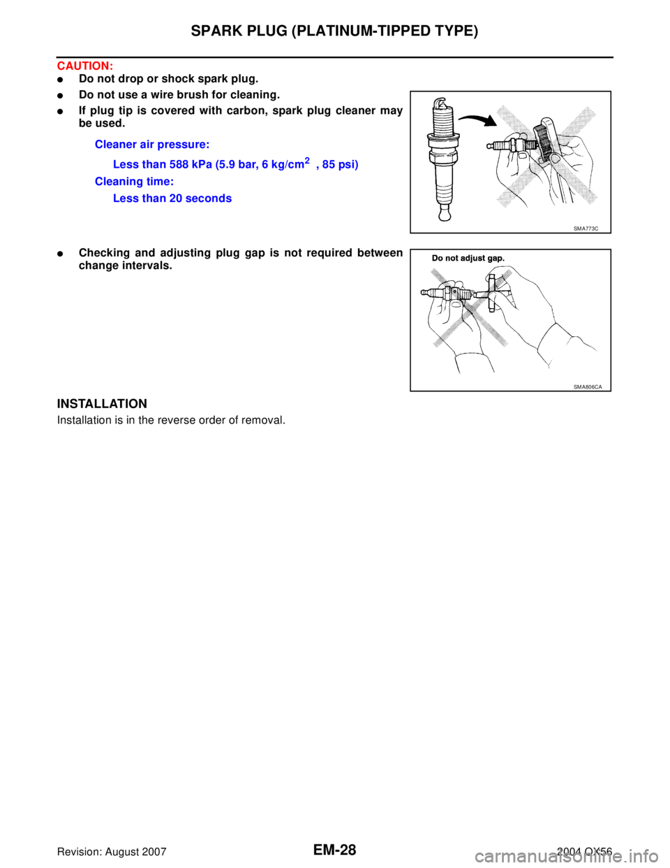
CAUTION:
�Do not drop or shock spark plug.
�Do not use a wire brush for cleaning.
�If plug tip is covered with carbon, spark plug cleaner may
be used.
�Checking and adjusting plug gap is not required between
change intervals.
INSTALLATION
Installation is in the reverse order of removal.Cleaner air pressure:
Less than 588 kPa (5.9 bar, 6 kg/cm
2 , 85 psi)
Cleaning time:
Less than 20 seconds
SM A77 3C
SM A80 6CA

 using Tool.
CAUTION:
Do not damage mating surface.
3. Remove the oil strainer from")
 bolts in numerical order as shown.
4. Install the oil pan drain plug.
5. Installa")