Page 1187 of 3371

DI-84
REAR VIEW MONITOR
Revision: August 20072004 QX56
Rear View Is Not Displayed With The A/T Selector Lever In R PositionEKS007RC
1. BACK-UP LAMP INSPECTION
1. Turn ignition switch ON.
2. Shift A/T selector lever to R position.
Does back-up lamp illuminate?
YES >> GO TO 2.
NO >> Check back-up lamp system. Refer to LT-106, "
BACK-UP LAMP" .
2. CHECK REVERSE POSITION INPUT SIGNAL
With CONSULT-II
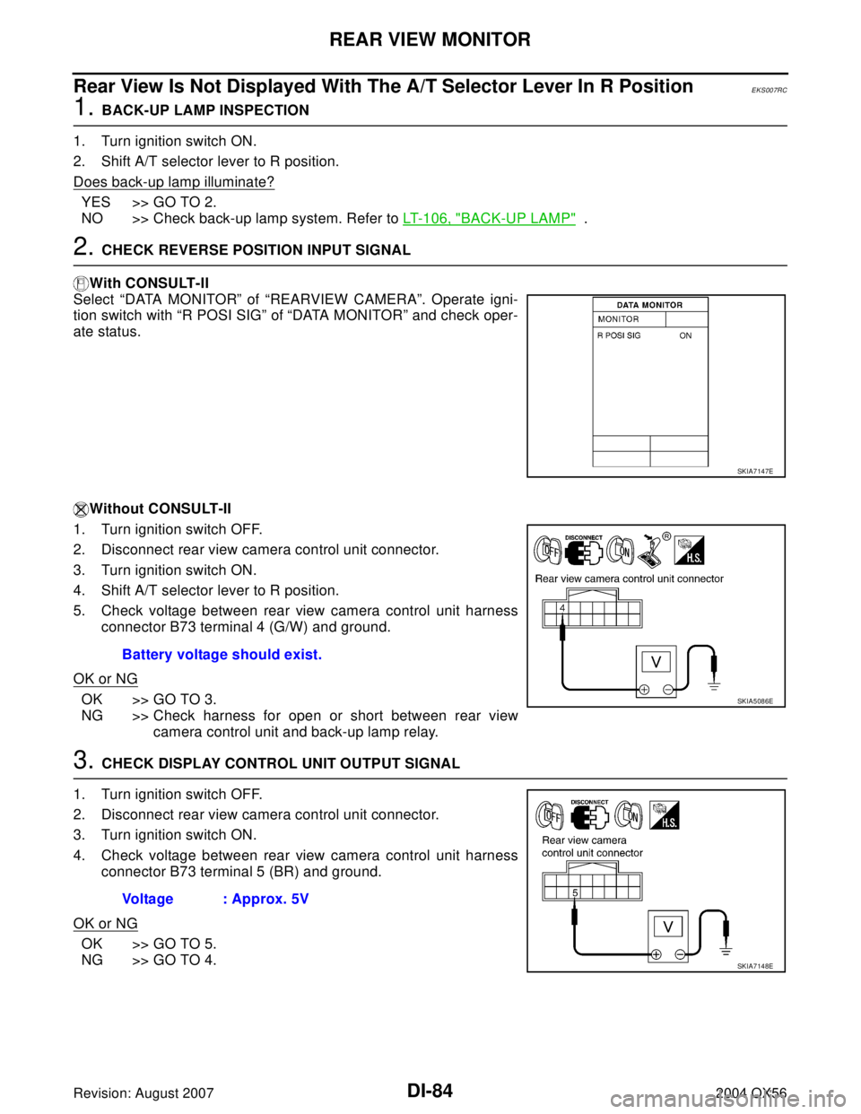
Select “DATA MONITOR” of “REARVIEW CAMERA”. Operate igni-
tion switch with “R POSI SIG” of “DATA MONITOR” and check oper-
ate status.
Without CONSULT-II
1. Turn ignition switch OFF.
2. Disconnect rear view camera control unit connector.
3. Turn ignition switch ON.
4. Shift A/T selector lever to R position.
5. Check voltage between rear view camera control unit harness
connector B73 terminal 4 (G/W) and ground.
OK or NG
OK >> GO TO 3.
NG >> Check harness for open or short between rear view
camera control unit and back-up lamp relay.
3. CHECK DISPLAY CONTROL UNIT OUTPUT SIGNAL
1. Turn ignition switch OFF.
2. Disconnect rear view camera control unit connector.
3. Turn ignition switch ON.
4. Check voltage between rear view camera control unit harness
connector B73 terminal 5 (BR) and ground.
OK or NG
OK >> GO TO 5.
NG >> GO TO 4.
SKIA7147E
Battery voltage should exist.
SKIA5086E
Voltage : Approx. 5V
SKIA7148E
Page 1191 of 3371

DI-88
REAR VIEW MONITOR
Revision: August 20072004 QX56
13. CHECK REAR VIEW CAMERA CONTROL UNIT COMPOSITE SIGNAL
1. Connect rear view camera control unit connector and display
unit connector.
2. Turn ignition switch ON.
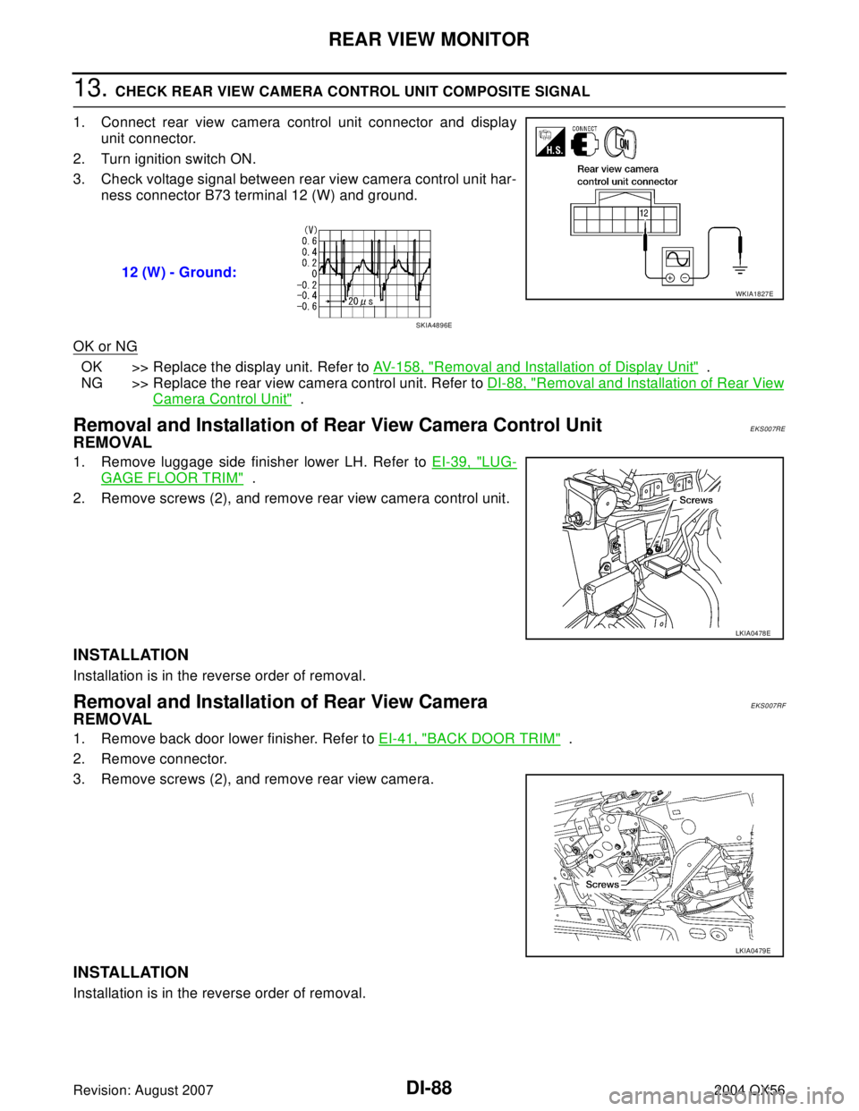
3. Check voltage signal between rear view camera control unit har-
ness connector B73 terminal 12 (W) and ground.
OK or NG
OK >> Replace the display unit. Refer to AV- 1 5 8 , "Removal and Installation of Display Unit" .
NG >> Replace the rear view camera control unit. Refer to DI-88, "
Removal and Installation of Rear View
Camera Control Unit" .
Removal and Installation of Rear View Camera Control UnitEKS007RE
REMOVAL
1. Remove luggage side finisher lower LH. Refer to EI-39, "LUG-
GAGE FLOOR TRIM" .
2. Remove screws (2), and remove rear view camera control unit.
INSTALLATION
Installation is in the reverse order of removal.
Removal and Installation of Rear View CameraEKS007RF
REMOVAL
1. Remove back door lower finisher. Refer to EI-41, "BACK DOOR TRIM" .
2. Remove connector.
3. Remove screws (2), and remove rear view camera.
INSTALLATION
Installation is in the reverse order of removal.12 (W) - Ground:
WKIA1827E
SKIA4896E
LKIA0478E
LKIA0479E
Page 1836 of 3371

POSITIVE CRANKCASE VENTILATION
EC-645
C
D
E
F
G
H
I
J
K
L
MA
EC
Revision: August 20072004 QX56
POSITIVE CRANKCASE VENTILATIONPFP:11810
DescriptionUBS00HE5
SYSTEM DESCRIPTION
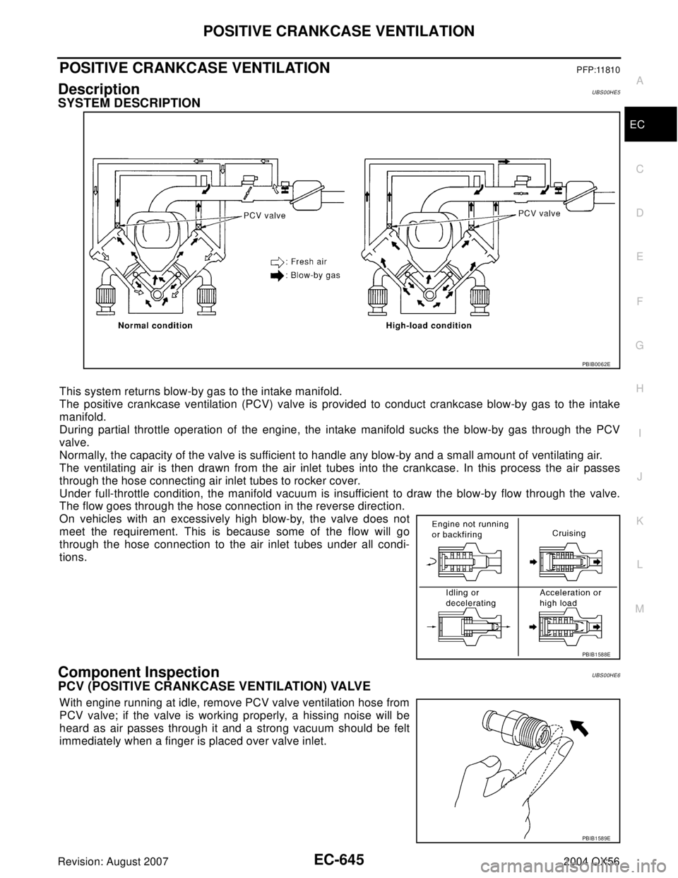
This system returns blow-by gas to the intake manifold.
The positive crankcase ventilation (PCV) valve is provided to conduct crankcase blow-by gas to the intake
manifold.
During partial throttle operation of the engine, the intake manifold sucks the blow-by gas through the PCV
valve.
Normally, the capacity of the valve is sufficient to handle any blow-by and a small amount of ventilating air.
The ventilating air is then drawn from the air inlet tubes into the crankcase. In this process the air passes
through the hose connecting air inlet tubes to rocker cover.
Under full-throttle condition, the manifold vacuum is insufficient to draw the blow-by flow through the valve.
The flow goes through the hose connection in the reverse direction.
On vehicles with an excessively high blow-by, the valve does not
meet the requirement. This is because some of the flow will go
through the hose connection to the air inlet tubes under all condi-
tions.
Component InspectionUBS00HE6
PCV (POSITIVE CRANKCASE VENTILATION) VALVE
With engine running at idle, remove PCV valve ventilation hose from
PCV valve; if the valve is working properly, a hissing noise will be
heard as air passes through it and a strong vacuum should be felt
immediately when a finger is placed over valve inlet.
PBIB0062E
PBIB1588E
PBIB1589E
Page 1855 of 3371
EI-14
FRONT BUMPER
Revision: August 20072004 QX56
3. Remove engine undercover.
4. Remove fog/turn lamp finisher and fog/turn lamp.
�Disconnect harnesses.
5. Remove engine underside cover.
6. Remove fasteners, release clips and remove front fascia assembly.
7. Remove plastic clips and remove upper energy absorber.
8. Remove upper bumper reinforcement.
9. Remove plastic clips and remove lower energy absorber.
10. Remove front bumper stays and front bumper side brackets, LH and RH.
INSTALLATION
Installation is in the reverse order of removal.
Page 1857 of 3371

EI-16
REAR BUMPER
Revision: August 20072004 QX56
1. Remove quarter panel trim covers LH and RH.
2. Disconnect sonar sensor harness connector under rear fascia assembly.
3. Release retainer clips on both sides of rear fascia assembly with a 1/4 turn and top S clips and remove
fascia assembly.
4. Remove energy absorber.
5. Remove reinforcement assembly.
6. Remove nuts and remove retainer assembly.
�Remove S clips from retainer assembly.
7. Disconnect sonar sensors from sonar sensor retainers.
8. Remove sonar sensors and harness from rear fascia assembly.
�Disconnect sonar sensors from harness.
�Remove sonar sensor retainers from rear fascia assembly.
9. Remove bolts on each side of tow hitch and remove tow hitch.
10. Remove drafter duct from under LH quarter panel.
Installation is in the reverse order of removal.
1. Retainer assembly 2. Plastic clip 3. S clip
4. Reinforcement assembly 5. Energy absorber 6. Sonar sensor
7. Quarter panel trim cover LH 8. Drafter duct 9. Retainer clip
10. Rear fascia assembly 11. Sonar sensor retainer 12. Tow hitch
13. Sonar sensor harness 14. Quarter panel trim cover RH
Page 1858 of 3371
FRONT GRILLE
EI-17
C
D
E
F
G
H
J
K
L
MA
B
EI
Revision: August 20072004 QX56
FRONT GRILLEPFP:62310
Removal and InstallationEIS002X9
1. Remove bolts and nuts attaching grille.
2. Remove grille.
Installation is in the reverse order of removal.
WIIA0565E
Page 1860 of 3371
COWL TOP
EI-19
C
D
E
F
G
H
J
K
L
MA
B
EI
Revision: August 20072004 QX56
5. Remove wiper motor and connecting rod linkage. Refer to WW-29, "Removal and Installation of Wiper
Motor and Linkage" .
6. Disconnect windshield washer tube. Refer to WW-31, "
Washer Tube Layout" .
7. Remove water cut valve bracket from cowl top extension. Refer to CO-17, "
THERMOSTAT AND WATER
PIPING" .
8. Remove A/C line bracket from cowl top extension, Refer to ATC-162, "
REFRIGERANT LINES" for ATC
and ATC-162, "
REFRIGERANT LINES" for MTC.
9. Remove drain tube from each side of cowl top extension.
10. Remove cowl top extension.
Installation is in the reverse order of removal.
Page 1861 of 3371
EI-20
FRONT FENDER
Revision: August 20072004 QX56
FRONT FENDERPFP:63100
Removal and InstallationEIS002XB
1. Remove headlamp. Refer to LT- 3 3 , "Removal and Installation" .
2. Remove over fender. Refer to EI-21, "
OVER FENDER" .
3. Remove fender protector. Refer to EI-23, "
FENDER PROTECTOR" .
4. Remove hood stay. Refer to BL-12, "
HOOD" .
5. Remove front fender.
Installation is in the reverse order of removal.
WIIA0263E