Page 2058 of 3371

FUEL TANK
FL-13
C
D
E
F
G
H
I
J
K
L
MA
FL
Revision: August 20072004 QX56
19. Remove the fuel tank strap bolts while supporting the fuel tank
with a suitable lift jack.
20. Disconnect the EVAP hose from the molded clip in the top of the fuel tank while lowering the fuel tank.
21. Lower the fuel tank using a suitable lift jack and remove it.
22. If necessary, remove the lock ring using Tool.
23. If necessary, remove the fuel level sensor, fuel filter, and fuel
pump assembly.
CAUTION:
�Do not bend the float arm during removal.
�Avoid impacts such as dropping when handling the com-
ponents.
INSTALLATION
Installation is in the reverse order of removal.
�Connect the quick connector as follows:
–Check the connection for any damage or foreign materials.
–Align the connector with the pipe, then insert the connector straight into the pipe until a click is heard.
–After connecting the quick connector, make sure that the con-
nection is secure by checking as follows:
–Pull the tube and the connector to make sure they are securely
connected.
–Visually inspect the connector to make sure the two retainer tabs
are securely connected.
INSPECTION AFTER INSTALLATION
1. Turn the ignition switch ON but do not start engine, then check the fuel pipe and hose connections for
leaks while applying fuel pressure.
2. Start the engine and rev it above idle, then check that there are no fuel leaks at any of the fuel pipe and
hose connections.
LBIA0387E
Tool number : — (J-46536)
LBIA0389E
PBIC1653E
Page 2069 of 3371

FSU-10
COIL SPRING AND SHOCK ABSORBER
Revision: August 20072004 QX56
COIL SPRING AND SHOCK ABSORBERPFP:56210
Removal and InstallationEES0010K
REMOVAL
1. Remove the wheel and tire using power tool.
2. Remove the shock absorber lower bolt using power tool.
3. Remove the three shock absorber upper mounting nuts using
power tool.
4. Remove the coil spring and shock absorber assembly.
�Turn steering knuckle out to gain enough clearance for
removal.
INSTALLATION
Installation is in the reverse order of removal.
�The step in the shock absorber assembly lower seat faces outside of vehicle.
�Tighten all nuts and bolts to specification. Refer to FSU-5, "Components" .
�When installing wheel and tire, refer to WT-6, "Rotation" .
Disassembly and AssemblyEES0010L
DISASSEMBLY
1. Set the shock absorber in a vise, then loosen (without removing)
the piston rod lock nut as shown.
CAUTION:
Do not remove piston rod lock nut at this time.
2. Compress the spring using commercial service tool until the
shock absorber mounting insulator can be turned by hand.
WAR NIN G:
Make sure that the pawls of the two spring compressors are
firmly hooked on the spring. The spring compressors must
be tightened alternately and evenly so as not to tilt the
spring.
3. Remove the piston rod lock nut.
�Discard the piston rod lock nut, use a new nut for assembly.
INSPECTION AFTER DISASSEMBLY
Shock Absorber Assembly
�Check for smooth operation through a full stroke, both compression and extension.
�Check for oil leakage on welded or gland packing portions.
�Check piston rod for cracks, deformation or other damage and replace if necessary.
Mounting Insulator and Rubber Parts
Check cemented rubber-to-metal portion for separation or cracks. Check rubber parts for deterioration and
replace if necessary.
LEIA0093E
SSU0 02
SSU0 03
Page 2071 of 3371
FSU-12
STABILIZER BAR
Revision: August 20072004 QX56
STABILIZER BARPFP:54611
Removal and InstallationEES0010M
REMOVAL
1. Remove engine under cover using power tool.
2. Remove stabilizer bar mounting bracket bolts and connecting
rod nuts as shown, using power tool.
3. Remove bushings from stabilizer bar.
INSPECTION AFTER REMOVAL
�Check stabilizer bar for twist and deformation. Replace if necessary.
�Check rubber bushing for cracks, wear and deterioration. Replace if necessary.
INSTALLATION
Installation is in the reverse order of removal.
�Tighten all nuts and bolts to specification. Refer to FSU-5, "Components" .
LEIA0094E
Page 2072 of 3371
UPPER LINK
FSU-13
C
D
F
G
H
I
J
K
L
MA
B
FSU
Revision: August 20072004 QX56
UPPER LINKPFP:54524
Removal and InstallationEES0010N
REMOVAL
1. Remove the wheel and tire using power tool.
2. Remove wheel opening shield.
3. Remove cotter pin and nut from upper link ball joint.
4. Separate upper link ball joint stud from steering knuckle using
Tool.
�Support lower link with jack.
5. Remove upper link mounting bolts and nuts.
INSPECTION AFTER REMOVAL
Upper Link
Check for deformation and cracks. Replace if necessary.
Upper Link Ball Joint
Check for distortion and damage. Replace if necessary.
INSTALLATION
Installation is in the reverse order of removal.
�Tighten all nuts and bolts to specification. Refer to FSU-5, "Components" .
�When installing wheel and tire, refer to WT-6, "Rotation" .
�After installation, check that the front wheel alignment is within specification. Refer to FSU-6, "Front
Wheel Alignment" . Tool number : ST29020001 (J24319-01)
LEIA0095E
LEIA0096E
Page 2073 of 3371

FSU-14
LOWER LINK
Revision: August 20072004 QX56
LOWER LINKPFP:55020
Removal and InstallationEES0010O
REMOVAL
1. Remove the wheel and tire using power tool.
2. Remove lower shock absorber bolt.
3. Remove stabilizer bar connecting rod lower nut using power tool, then separate connecting rod from lower
link. Refer to FSU-12, "
Removal and Installation" .
4. Remove drive shaft, if equipped. Refer to FAX-7, "
Removal and Installation" .
5. Remove pinch bolt from steering knuckle using power tool, then
separate lower link ball joint from steering knuckle.
6. Remove lower link adjusting bolts and nuts, then the lower link.
INSPECTION AFTER REMOVAL
Lower Link
Check for deformation and cracks. Replace if necessary.
Lower Link Bushing
Check for distortion and damage. Replace if necessary.
INSTALLATION
Installation is in the reverse order of removal.
�Tighten all nuts and bolts to specification. Refer to FSU-5, "Components" .
�When installing wheel and tire, refer to WT-6, "Rotation" .
�After installation, check that the front wheel alignment is within specification. Refer to FSU-6, "Front
Wheel Alignment" .
LEIA0097E
WEIA0079E
Page 2078 of 3371
KNUCKLE
FSU-19
C
D
F
G
H
I
J
K
L
MA
B
FSU
Revision: August 20072004 QX56
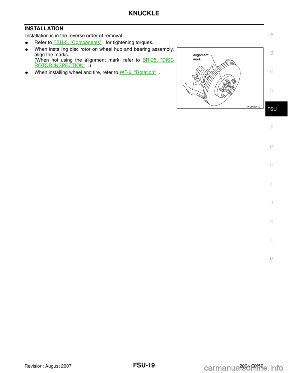
INSTALLATION
Installation is in the reverse order of removal.
�Refer to FSU-5, "Components" for tightening torques.
�When installing disc rotor on wheel hub and bearing assembly,
align the marks.
(When not using the alignment mark, refer to BR-25, "
DISC
ROTOR INSPECTION" .)
�When installing wheel and tire, refer to WT-6, "Rotation" .
WDIA0044E
Page 2116 of 3371

SERVICE INFORMATION FOR ELECTRICAL INCIDENT
GI-35
C
D
E
F
G
H
I
J
K
L
MB
GI
Revision: August 20072004 QX56
Control Units and Electrical PartsEAS0014P
PRECAUTIONS
�Never reverse polarity of battery terminals.
�Install only parts specified for a vehicle.
�Before replacing the control unit, check the input and output and
functions of the component parts.
�Do not apply excessive force when disconnecting a connector.
�If a connector is installed by tightening bolts, loosen bolt mount-
ing it, then take it out by hand.
�Before installing a connector, make sure the terminal is not bent
or damaged, and then correctly connect it.
When installing a connector by tightening bolts, fix it by tighten-
ing the mounting bolt until the painted projection of the connec-
tor becomes even with the surface.
�For removal of the lever type connector, pull the lever up to the
direction pointed to by the arrow A in the figure, and then
remove the connector.
�For installation of the lever type connector, pull down the lever to
the direction pointed by the arrow B in the figure, and then push
the connector until a clicking noise is heard.
SAIA0251E
SAIA0252E
SAIA0253E
SAIA0254E
Page 2149 of 3371
GW-14
REAR WINDOW GLASS AND MOLDING
Revision: August 20072004 QX56
6. Remove the rear glass hinges.
INSTALLATION
Installation is in the reverse order of removal.