Page 2438 of 4500

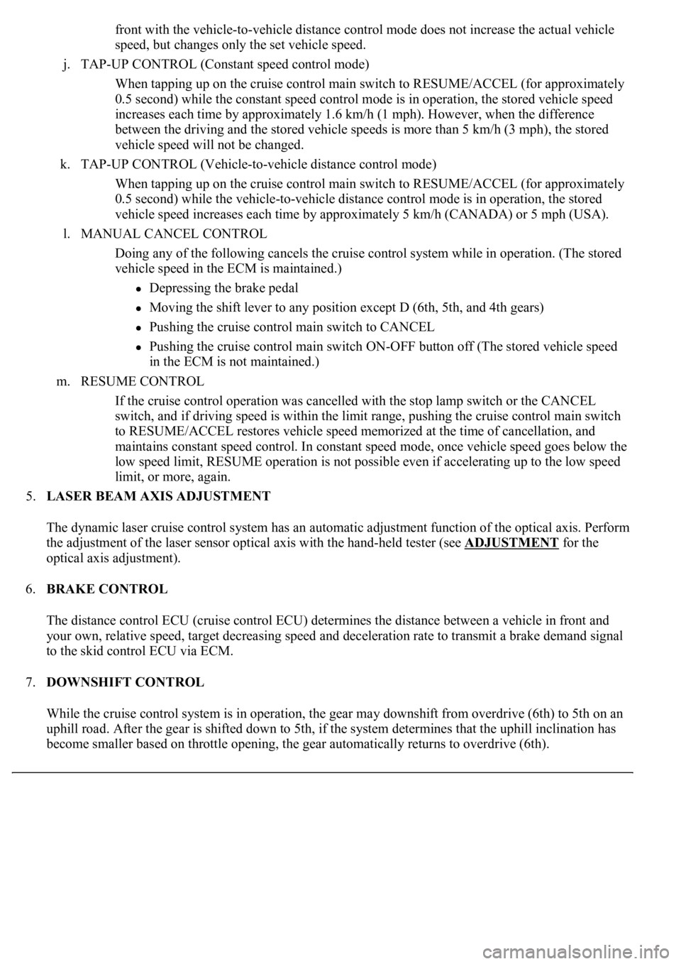
front with the vehicle-to-vehicle distance control mode does not increase the actual vehicle
speed, but changes only the set vehicle speed.
j. TAP-UP CONTROL (Constant speed control mode)
When tapping up on the cruise control main switch to RESUME/ACCEL (for approximately
0.5 second) while the constant speed control mode is in operation, the stored vehicle speed
increases each time by approximately 1.6 km/h (1 mph). However, when the difference
between the driving and the stored vehicle speeds is more than 5 km/h (3 mph), the stored
vehicle speed will not be changed.
k. TAP-UP CONTROL (Vehicle-to-vehicle distance control mode)
When tapping up on the cruise control main switch to RESUME/ACCEL (for approximately
0.5 second) while the vehicle-to-vehicle distance control mode is in operation, the stored
vehicle speed increases each time by approximately 5 km/h (CANADA) or 5 mph (USA).
l. MANUAL CANCEL CONTROL
<00270052004c0051004a000300440051005c00030052004900030057004b0048000300490052004f004f0052005a004c0051004a000300460044005100460048004f005600030057004b00480003004600550058004c005600480003004600520051005700
550052004f00030056005c00560057004800500003005a004b[ile in operation. (The stored
vehicle speed in the ECM is maintained.)
Depressing the brake pedal
<003000520059004c0051004a00030057004b004800030056004b004c004900570003004f0048005900480055000300570052000300440051005c0003005300520056004c0057004c0052005100030048005b0046004800530057000300270003000b001900
57004b000f000300180057004b000f00030044005100470003[4th gears)
Pushing the cruise control main switch to CANCEL
Pushing the cruise control main switch ON-OFF button off (The stored vehicle speed
in the ECM is not maintained.)
m. RESUME CONTROL
If the cruise control operation was cancelled with the stop lamp switch or the CANCEL
switch, and if driving speed is within the limit range, pushing the cruise control main switch
to RESUME/ACCEL restores vehicle speed memorized at the time of cancellation, and
maintains constant speed control. In constant speed mode, once vehicle speed goes below the
low speed limit, RESUME operation is not possible even if accelerating up to the low speed
limit, or more, again.
5.LASER BEAM AXIS ADJUSTMENT
The dynamic laser cruise control system has an automatic adjustment function of the optical axis. Perform
the adjustment of the laser sensor optical axis with the hand-held tester (see ADJUSTMENT
for the
optical axis adjustment).
6.BRAKE CONTROL
The distance control ECU (cruise control ECU) determines the distance between a vehicle in front and
your own, relative speed, target decreasing speed and deceleration rate to transmit a brake demand signal
to the skid control ECU via ECM.
7.DOWNSHIFT CONTROL
While the cruise control system is in operation, the gear may downshift from overdrive (6th) to 5th on an
uphill road. After the gear is shifted down to 5th, if the system determines that the uphill inclination has
become smaller based on throttle opening, the gear automatically returns to overdrive (6th).
Page 2440 of 4500
NO CAN SYSTEM DTC (GO TO STEP 6)
6.(SEE DTC CHECK/CLEAR
)
Go to Next Step.
7.DTC CHECK (OTHER THAN MULTIPLEX AND CAN SYSTEM DTC) (SEE DTC
CHECK/CLEAR )
TROUBLE CODE (GO TO STEP 8)
NORMAL SYSTEM CODE (GO TO STEP 9)
8.(SEE DIAGNOSTIC TROUBLE CODE CHART
)
GO TO STEP 12
9.PROBLEM SYMPTOM SIMULATION
SYMPTOM DOES NOT OCCUR (GO TO STEP 10)
SYMPTOM OCCURS (GO TO STEP 11)
10.SYMPTOM SIMULATION (SEE ELECTRONIC CIRCUIT INSPECTION PROCEDURE
)
Go to Next Step.
11.(SEE PROBLEM SYMPTOMS TABLE
)
Go to Next Step.
12.CIRCUIT INSPECTION (SEE DTC P0500 VEHICLE SPEED SENSOR CIRCUIT
MALFUNCTION, DTC P0503 VEHICLE SPEED SENSOR CIRCUIT MALFUNCTION -
DIAGNOSIS CIRCUIT
)
Go to Next Step.
13.(SEE TERMINALS OF ECU
)
Go to Next Step.
14.PROBLEM IDENTIFICATION
Go to Next Step.
15.REPAIR OR REPLACE
Page 2452 of 4500
1.DISTANCE CONTROL ECU
Fig. 20: Identifying ECU Terminals
Courtesy of TOYOTA MOTOR SALES, U.S.A., INC.
ECU TERMINALS VOLTAGE AND RESISTANCE
a. Reference: waveform 1
HINT:
Terminal: LRDD - GND
Symbols (Terminals No.)Wiring
ColorTerminal
DescriptionConditionSpecified Condition
+B - GND (D2-1 - D2-12)R-B - BRBatteryAlways10 to 14 V
CANH (D2 - 8)LG
CAN
communication
signalCAN
communication
circuit
-
CANL (D2 - 9)L
CAN
communication
signalCAN
communication
circuit
-
SGND - Body ground
(D2-10 - Body ground)BR - Body
groundGroundAlwaysBelow 1 ohms
GND - Body ground (D2-
12 - Body ground)BR - Body
groundGroundAlwaysBelow 1 ohms
IGB - GND (D2-13 - D2-
12)L-O - BRIgnition switch ON
signalIgnition switch OFF
--> ONBelow 1 V --> 10 to
14 V
LRDD - GND (D2-22 -
D2-12)P-L - BRLaser sensor input
signalIgnition switch ONPulse generation (see
waveform 1)
LRRD - GND (D2-23 -
D2-12)L-Y - BRLaser sensor output
signalIgnition switch ONPulse generation (see
waveform 2)
Page 2455 of 4500
Fig. 24: ECM Terminals Voltage And Resistance Chart
Courtesy of TOYOTA MOTOR SALES, U.S.A., INC.
If the value is not within the standard range, some defects on the vehicle are suspected.
d.LASER SENSOR
Page 2456 of 4500
Fig. 25: Identifying Laser Sensor Terminals
Courtesy of TOYOTA MOTOR SALES, U.S.A., INC.
LASER SENSOR TERMINALS VOLTAGE AND RESISTANCE
a. Reference: waveform 1
HINT:
Terminal: LRDD - SGND
Gauge set: 1 V/DIV, 2 ms/DIV
Symbols (Terminal No.)Wiring
ColorTerminal
DescriptionConditionSpecified Condition
LGND - Body ground (L1-
1 - Body ground)B-L - Body
groundDistance signalAlwaysBelow 1 ohms
SGND - Body ground (L1-
2 - Body ground)B-R - Body
groundGroundAlwaysBelow 1 ohms
LRDD - SGND (L1-3 -
L1-2)B-O - B-RLaser sensor
output signalIgnition
switch ONPulse generation (see
waveform 1)
LRRD - SGND (L1-4 -
L1-2)B-Y - B-RLaser sensor input
signalIgnition
switch ONPulse generation (see
waveform 2)
IGB - SGND (L1-5 - L1-2)B - B-RPower sourceIgnition
switch ON10 to 14 V
Page 2463 of 4500
If a malfunction occurs in the vehicle speed sensors, the stop lamp switch, or other related parts during
cruise control driving, the ECU actuates AUTO CANCEL of the cruise control and blinks the CRUISE
main indicator light. This indicator light informs the driver of the malfunction. At the same time, the
malfunction is stored as a diagnostic trouble code.
Fig. 32: Identifying Blinking Pattern Of CRUISE Main Indicator Light
Courtesy of TOYOTA MOTOR SALES, U.S.A., INC.
1.DTC CHECK
a. Connect the hand-held tester to the DLC3.
b. Turn the ignition switch to the ON position.
c. Read the DTCs by following the prompts on the tester screen.
2.DTC CLEAR
a. Connect the hand-held tester to the DLC3.
b. Turn the ignition switch to the ON position.
c. Clear the DTCs following the prompts on the tester screen.
HINT:
Refer to the han
d-held tester operators manual for further details.
Page 2467 of 4500

Courtesy of TOYOTA MOTOR SALES, U.S.A., INC.
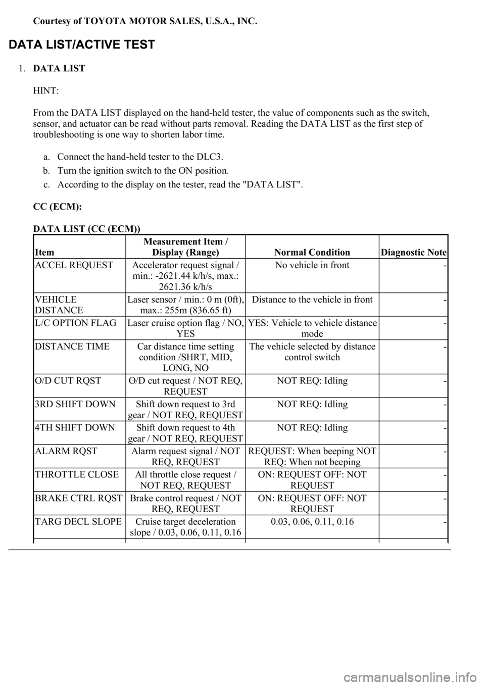
1.DATA LIST
HINT:
From the DATA LIST displayed on the hand-held tester, the value of components such as the switch,
sensor, and actuator can be read without parts removal. Reading the DATA LIST as the first step of
troubleshooting is one way to shorten labor time.
a. Connect the hand-held tester to the DLC3.
b. Turn the ignition switch to the ON position.
c. According to the display on the tester, read the "DATA LIST".
CC (ECM):
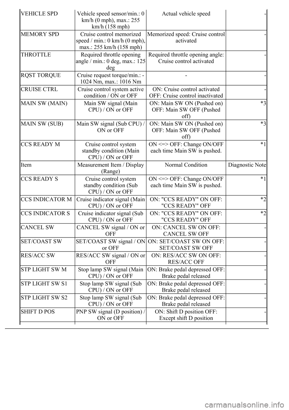
DATA LIST (CC (ECM))
Item
Measurement Item /
Display (Range)
Normal ConditionDiagnostic Note
ACCEL REQUESTAccelerator request signal /
min.: -2621.44 k/h/s, max.:
2621.36 k/h/sNo vehicle in front-
VEHICLE
DISTANCELaser sensor / min.: 0 m (0ft),
max.: 255m (836.65 ft)Distance to the vehicle in front-
L/C OPTION FLAGLaser cruise option flag / NO,
YESYES: Vehicle to vehicle distance
mode-
DISTANCE TIMECar distance time setting
condition /SHRT, MID,
LONG, NOThe vehicle selected by distance
control switch-
O/D CUT RQSTO/D cut request / NOT REQ,
REQUESTNOT REQ: Idling-
3RD SHIFT DOWNShift down request to 3rd
gear / NOT REQ, REQUESTNOT REQ: Idling-
4TH SHIFT DOWNShift down request to 4th
gear / NOT REQ, REQUESTNOT REQ: Idling-
ALARM RQSTAlarm request signal / NOT
REQ, REQUESTREQUEST: When beeping NOT
REQ: When not beeping-
THROTTLE CLOSEAll throttle close request /
NOT REQ, REQUESTON: REQUEST OFF: NOT
REQUEST-
BRAKE CTRL RQSTBrake control request / NOT
REQ, REQUESTON: REQUEST OFF: NOT
REQUEST-
TARG DECL SLOPECruise target deceleration
slope / 0.03, 0.06, 0.11, 0.160.03, 0.06, 0.11, 0.16-
Page 2468 of 4500

VEHICLE SPDVehicle speed sensor/min.: 0
km/h (0 mph), max.: 255
km/h (158 mph)Actual vehicle speed-
MEMORY SPDCruise control memorized
speed / min.: 0 km/h (0 mph),
max.: 255 km/h (158 mph)Memorized speed: Cruise control
activated-
THROTTLERequired throttle opening
angle / min.: 0 deg, max.: 125
degRequired throttle opening angle:
Cruise control activated-
RQST TORQUECruise request torque/min.: -
1024 Nm, max.: 1016 Nm--
CRUISE CTRLCruise control system active
condition / ON or OFFON: Cruise control activated
OFF: Cruise control inactivated-
MAIN SW (MAIN)Main SW signal (Main
CPU) / ON or OFFON: Main SW ON (Pushed on)
OFF: Main SW OFF (Pushed
off)*3
MAIN SW (SUB)Main SW signal (Sub CPU) /
ON or OFFON: Main SW ON (Pushed on)
OFF: Main SW OFF (Pushed
off)*3
CCS READY MCruise control system
standby condition (Main
CPU) / ON or OFFON <=> OFF: Change ON/OFF
each time Main SW is pushed.*1
ItemMeasurement Item / Display
(Range)Normal ConditionDiagnostic Note
CCS READY SCruise control system
standby condition (Sub
CPU) / ON or OFFON <=> OFF: Change ON/OFF
each time Main SW is pushed.*1
CCS INDICATOR MCruise indicator signal (Main
CPU) / ON or OFFON: "CCS READY" ON OFF:
"CCS READY" OFF*2
CCS INDICATOR SCruise indicator signal (Sub
CPU) / ON or OFFON: "CCS READY" ON OFF:
"CCS READY" OFF*2
CANCEL SWCANCEL SW signal / ON or
OFFON: CANCEL SW ON OFF:
CANCEL SW OFF-
SET/COAST SWSET/COAST SW signal / ON
or OFFON: SET/COAST SW ON OFF:
SET/COAST SW OFF-
RES/ACC SWRES/ACC SW signal / ON or
OFFON: RES/ACC SW ON OFF:
RES/ACC OFF-
STP LIGHT SW MStop lamp SW signal (Main
CPU) / ON or OFFON: Brake pedal depressed OFF:
Brake pedal released-
STP LIGHT SW S1Stop lamp SW signal (Sub
CPU) / ON or OFFON: Brake pedal depressed OFF:
Brake pedal released-
STP LIGHT SW S2Stop lamp SW signal (Sub
CPU) / ON or OFFON: Brake pedal depressed OFF:
Brake pedal released-
SHIFT D POSPNP SW signal (D position) /
ON or OFFON: Shift D position OFF:
Except shift D position-