2003 LEXUS LS430 sensor
[x] Cancel search: sensorPage 2419 of 4500
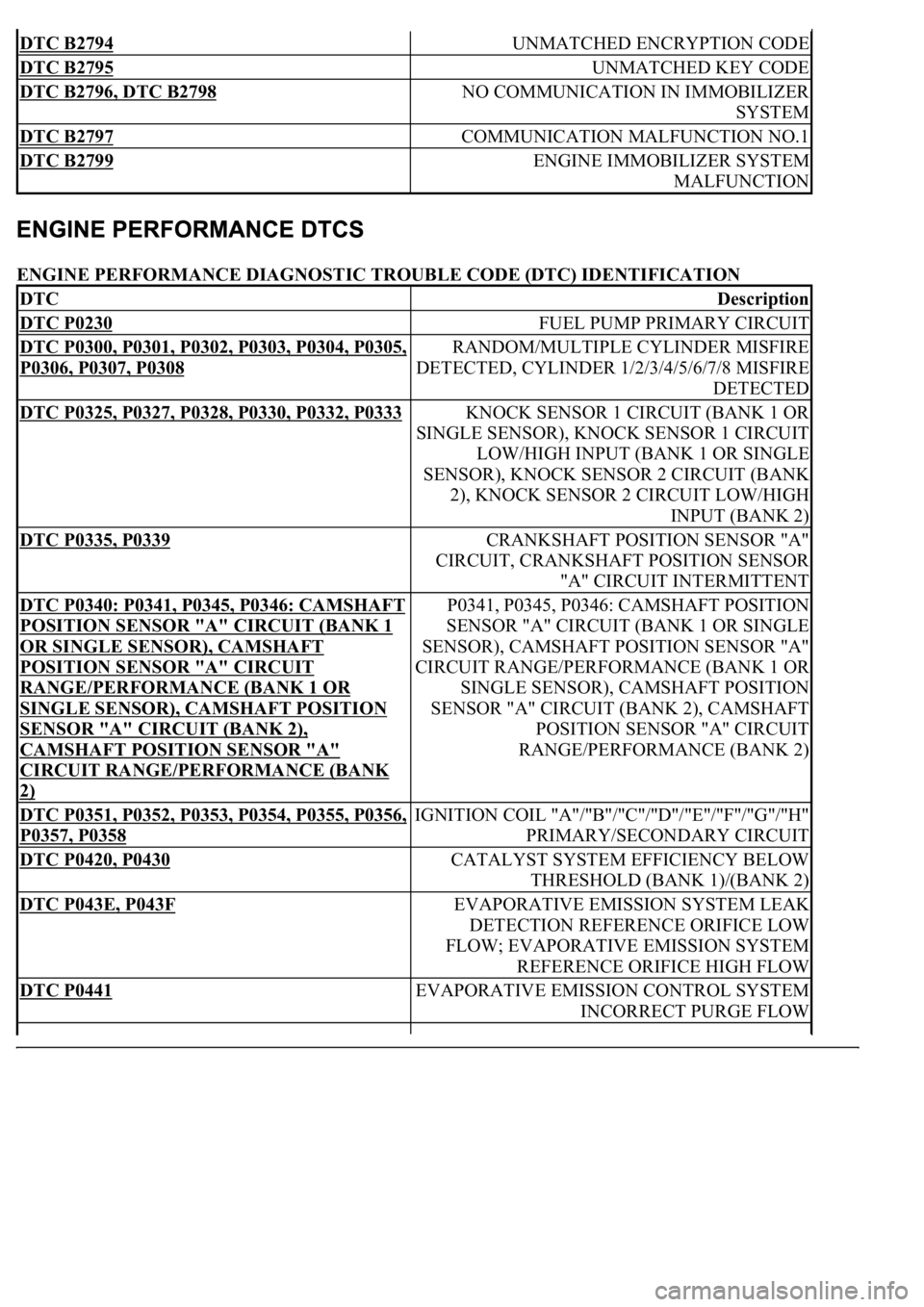
ENGINE PERFORMANCE DIAGNOSTIC TROUBLE CODE (DTC) IDENTIFICATION
DTC B2794 UNMATCHED ENCRYPTION CODE
DTC B2795 UNMATCHED KEY CODE
DTC B2796, DTC B2798 NO COMMUNICATION IN IMMOBILIZER
SYSTEM
DTC B2797 COMMUNICATION MALFUNCTION NO.1
DTC B2799 ENGINE IMMOBILIZER SYSTEM
MALFUNCTION
DTCDescription
DTC P0230 FUEL PUMP PRIMARY CIRCUIT
DTC P0300, P0301, P0302, P0303, P0304, P0305,
P0306, P0307, P0308
RANDOM/MULTIPLE CYLINDER MISFIRE
DETECTED, CYLINDER 1/2/3/4/5/6/7/8 MISFIRE
DETECTED
DTC P0325, P0327, P0328, P0330, P0332, P0333 KNOCK SENSOR 1 CIRCUIT (BANK 1 OR
SINGLE SENSOR), KNOCK SENSOR 1 CIRCUIT
LOW/HIGH INPUT (BANK 1 OR SINGLE
SENSOR), KNOCK SENSOR 2 CIRCUIT (BANK
2), KNOCK SENSOR 2 CIRCUIT LOW/HIGH
INPUT (BANK 2)
DTC P0335, P0339 CRANKSHAFT POSITION SENSOR "A"
CIRCUIT, CRANKSHAFT POSITION SENSOR
"A" CIRCUIT INTERMITTENT
DTC P0340: P0341, P0345, P0346: CAMSHAFT
POSITION SENSOR "A" CIRCUIT (BANK 1
OR SINGLE SENSOR), CAMSHAFT
POSITION SENSOR "A" CIRCUIT
RANGE/PERFORMANCE (BANK 1 OR
SINGLE SENSOR), CAMSHAFT POSITION
SENSOR "A" CIRCUIT (BANK 2),
CAMSHAFT POSITION SENSOR "A"
CIRCUIT RANGE/PERFORMANCE (BANK
2)
P0341, P0345, P0346: CAMSHAFT POSITION
SENSOR "A" CIRCUIT (BANK 1 OR SINGLE
SENSOR), CAMSHAFT POSITION SENSOR "A"
CIRCUIT RANGE/PERFORMANCE (BANK 1 OR
SINGLE SENSOR), CAMSHAFT POSITION
SENSOR "A" CIRCUIT (BANK 2), CAMSHAFT
POSITION SENSOR "A" CIRCUIT
RANGE/PERFORMANCE (BANK 2)
DTC P0351, P0352, P0353, P0354, P0355, P0356,
P0357, P0358
IGNITION COIL "A"/"B"/"C"/"D"/"E"/"F"/"G"/"H"
PRIMARY/SECONDARY CIRCUIT
DTC P0420, P0430 CATALYST SYSTEM EFFICIENCY BELOW
THRESHOLD (BANK 1)/(BANK 2)
DTC P043E, P043F EVAPORATIVE EMISSION SYSTEM LEAK
DETECTION REFERENCE ORIFICE LOW
FLOW; EVAPORATIVE EMISSION SYSTEM
REFERENCE ORIFICE HIGH FLOW
DTC P0441 EVAPORATIVE EMISSION CONTROL SYSTEM
INCORRECT PURGE FLOW
Page 2420 of 4500
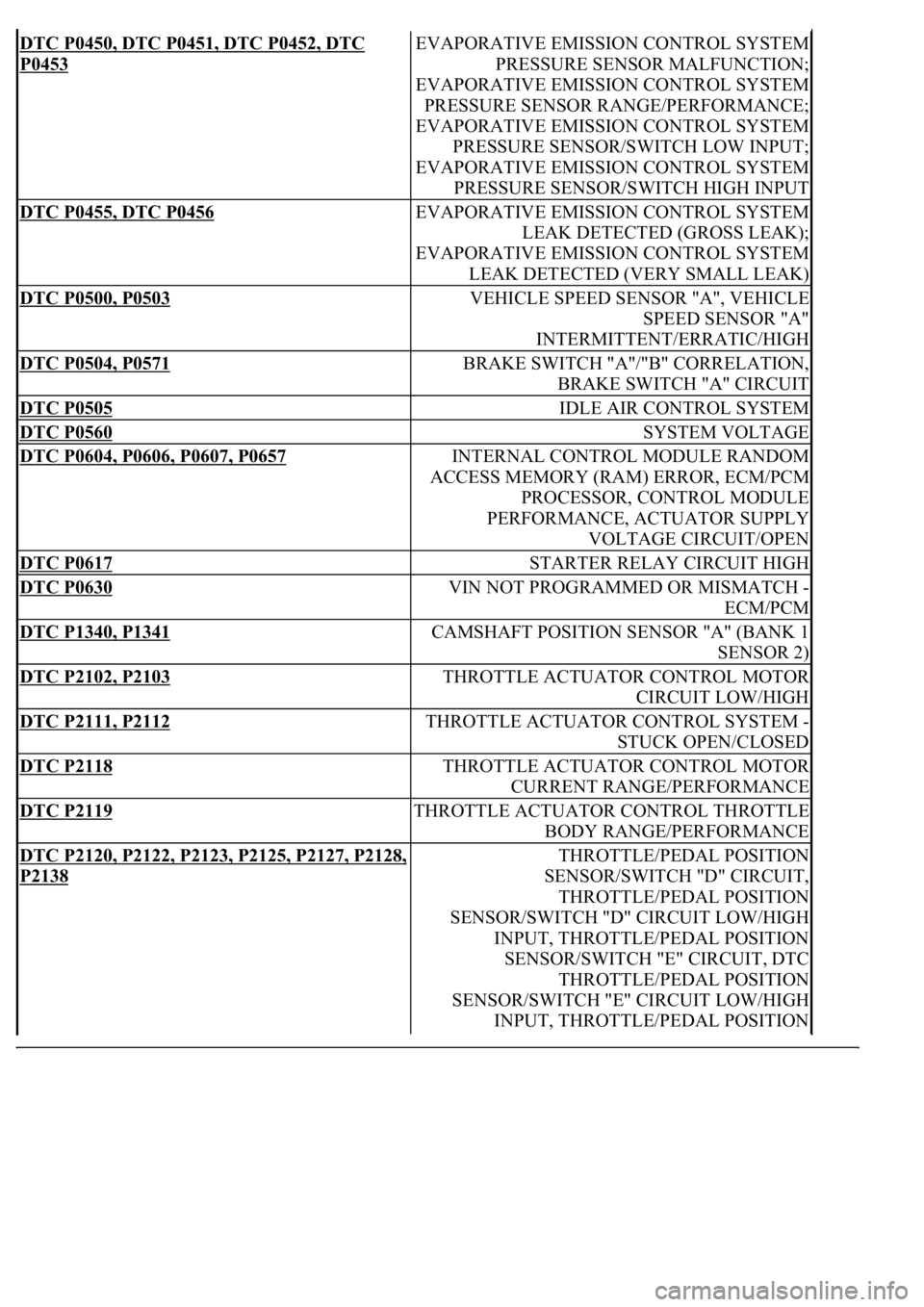
DTC P0450, DTC P0451, DTC P0452, DTC
P0453
EVAPORATIVE EMISSION CONTROL SYSTEM
PRESSURE SENSOR MALFUNCTION;
EVAPORATIVE EMISSION CONTROL SYSTEM
PRESSURE SENSOR RANGE/PERFORMANCE;
EVAPORATIVE EMISSION CONTROL SYSTEM
PRESSURE SENSOR/SWITCH LOW INPUT;
EVAPORATIVE EMISSION CONTROL SYSTEM
PRESSURE SENSOR/SWITCH HIGH INPUT
DTC P0455, DTC P0456 EVAPORATIVE EMISSION CONTROL SYSTEM
LEAK DETECTED (GROSS LEAK);
EVAPORATIVE EMISSION CONTROL SYSTEM
LEAK DETECTED (VERY SMALL LEAK)
DTC P0500, P0503 VEHICLE SPEED SENSOR "A", VEHICLE
SPEED SENSOR "A"
INTERMITTENT/ERRATIC/HIGH
DTC P0504, P0571 BRAKE SWITCH "A"/"B" CORRELATION,
BRAKE SWITCH "A" CIRCUIT
DTC P0505 IDLE AIR CONTROL SYSTEM
DTC P0560 SYSTEM VOLTAGE
DTC P0604, P0606, P0607, P0657 INTERNAL CONTROL MODULE RANDOM
ACCESS MEMORY (RAM) ERROR, ECM/PCM
PROCESSOR, CONTROL MODULE
PERFORMANCE, ACTUATOR SUPPLY
VOLTAGE CIRCUIT/OPEN
DTC P0617 STARTER RELAY CIRCUIT HIGH
DTC P0630 VIN NOT PROGRAMMED OR MISMATCH -
ECM/PCM
DTC P1340, P1341 CAMSHAFT POSITION SENSOR "A" (BANK 1
SENSOR 2)
DTC P2102, P2103 THROTTLE ACTUATOR CONTROL MOTOR
CIRCUIT LOW/HIGH
DTC P2111, P2112 THROTTLE ACTUATOR CONTROL SYSTEM -
STUCK OPEN/CLOSED
DTC P2118 THROTTLE ACTUATOR CONTROL MOTOR
CURRENT RANGE/PERFORMANCE
DTC P2119 THROTTLE ACTUATOR CONTROL THROTTLE
BODY RANGE/PERFORMANCE
DTC P2120, P2122, P2123, P2125, P2127, P2128,
P2138
THROTTLE/PEDAL POSITION
SENSOR/SWITCH "D" CIRCUIT,
THROTTLE/PEDAL POSITION
SENSOR/SWITCH "D" CIRCUIT LOW/HIGH
INPUT, THROTTLE/PEDAL POSITION
SENSOR/SWITCH "E" CIRCUIT, DTC
THROTTLE/PEDAL POSITION
SENSOR/SWITCH "E" CIRCUIT LOW/HIGH
INPUT, THROTTLE/PEDAL POSITION
Page 2421 of 4500
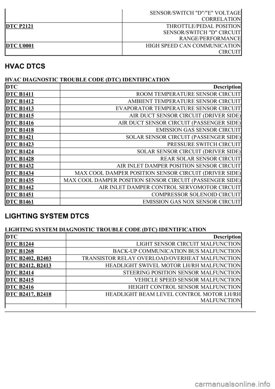
HVAC DIAGNOSTIC TROUBLE CODE (DTC) IDENTIFICATION
LIGHTING SYSTEM DIAGNOSTIC TROUBLE CODE (DTC) IDENTIFICATION
SENSOR/SWITCH "D"/"E" VOLTAGE
CORRELATION
DTC P2121 THROTTLE/PEDAL POSITION
SENSOR/SWITCH "D" CIRCUIT
RANGE/PERFORMANCE
DTC U0001 HIGH SPEED CAN COMMUNICATION
CIRCUIT
DTCDescription
DTC B1411 ROOM TEMPERATURE SENSOR CIRCUIT
DTC B1412 AMBIENT TEMPERATURE SENSOR CIRCUIT
DTC B1413 EVAPORATOR TEMPERATURE SENSOR CIRCUIT
DTC B1415 AIR DUCT SENSOR CIRCUIT (DRIVER SIDE)
DTC B1416 AIR DUCT SENSOR CIRCUIT (PASSENGER SIDE)
DTC B1418 EMISSION GAS SENSOR CIRCUIT
DTC B1421 SOLAR SENSOR CIRCUIT (PASSENGER SIDE)
DTC B1423 PRESSURE SWITCH CIRCUIT
DTC B1424 SOLAR SENSOR CIRCUIT (DRIVER SIDE)
DTC B1428 REAR SOLAR SENSOR CIRCUIT
DTC B1432 AIR INLET DAMPER POSITION SENSOR CIRCUIT
DTC B1434 MAX COOL DAMPER POSITION SENSOR CIRCUIT (DRIVER SIDE)
DTC B1435 MAX COOL DAMPER POSITION SENSOR CIRCUIT (PASSENGER SIDE)
DTC B1442 AIR INLET DAMPER CONTROL SERVOMOTOR CIRCUIT
DTC B1451 COMPRESSOR SOLENOID CIRCUIT
DTC B1461 EMISSION GAS NOX SENSOR CIRCUIT
DTCDescription
DTC B1244 LIGHT SENSOR CIRCUIT MALFUNCTION
DTC B1268 BACK-UP COMMUNICATION BUS MALFUNCTION
DTC B2402, B2403 TRANSISTOR RELAY OVERLOAD/OVERHEAT MALFUNCTION
DTC B2412, B2413 HEADLIGHT SWIVEL MOTOR LH/RH MALFUNCTION
DTC B2414 STEERING POSITION SENSOR MALFUNCTION
DTC B2415 VEHICLE SPEED SENSOR MALFUNCTION
DTC B2416 HEIGHT CONTROL SENSOR MALFUNCTION
DTC B2417, B2418 HEADLIGHT BEAM LEVEL CONTROL MOTOR LH/RH
MALFUNCTION
Page 2422 of 4500
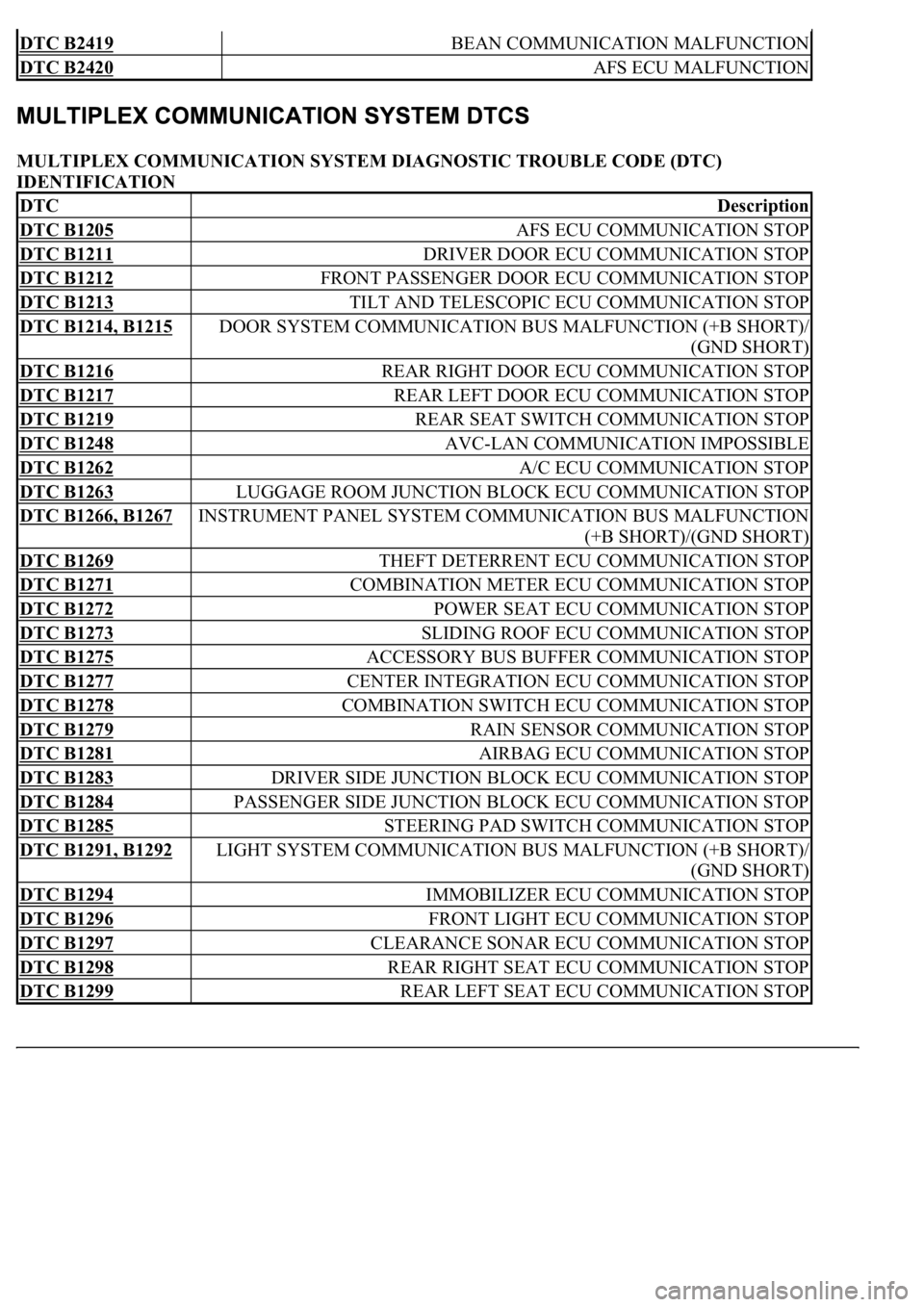
MULTIPLEX COMMUNICATION SYSTEM DIAGNOSTIC TROUBLE CODE (DTC)
IDENTIFICATION
DTC B2419 BEAN COMMUNICATION MALFUNCTION
DTC B2420 AFS ECU MALFUNCTION
DTCDescription
DTC B1205 AFS ECU COMMUNICATION STOP
DTC B1211 DRIVER DOOR ECU COMMUNICATION STOP
DTC B1212 FRONT PASSENGER DOOR ECU COMMUNICATION STOP
DTC B1213 TILT AND TELESCOPIC ECU COMMUNICATION STOP
DTC B1214, B1215 DOOR SYSTEM COMMUNICATION BUS MALFUNCTION (+B SHORT)/
(GND SHORT)
DTC B1216 REAR RIGHT DOOR ECU COMMUNICATION STOP
DTC B1217 REAR LEFT DOOR ECU COMMUNICATION STOP
DTC B1219 REAR SEAT SWITCH COMMUNICATION STOP
DTC B1248 AVC-LAN COMMUNICATION IMPOSSIBLE
DTC B1262 A/C ECU COMMUNICATION STOP
DTC B1263 LUGGAGE ROOM JUNCTION BLOCK ECU COMMUNICATION STOP
DTC B1266, B1267 INSTRUMENT PANEL SYSTEM COMMUNICATION BUS MALFUNCTION
(+B SHORT)/(GND SHORT)
DTC B1269 THEFT DETERRENT ECU COMMUNICATION STOP
DTC B1271 COMBINATION METER ECU COMMUNICATION STOP
DTC B1272 POWER SEAT ECU COMMUNICATION STOP
DTC B1273 SLIDING ROOF ECU COMMUNICATION STOP
DTC B1275 ACCESSORY BUS BUFFER COMMUNICATION STOP
DTC B1277 CENTER INTEGRATION ECU COMMUNICATION STOP
DTC B1278 COMBINATION SWITCH ECU COMMUNICATION STOP
DTC B1279 RAIN SENSOR COMMUNICATION STOP
DTC B1281 AIRBAG ECU COMMUNICATION STOP
DTC B1283 DRIVER SIDE JUNCTION BLOCK ECU COMMUNICATION STOP
DTC B1284 PASSENGER SIDE JUNCTION BLOCK ECU COMMUNICATION STOP
DTC B1285 STEERING PAD SWITCH COMMUNICATION STOP
DTC B1291, B1292 LIGHT SYSTEM COMMUNICATION BUS MALFUNCTION (+B SHORT)/
(GND SHORT)
DTC B1294 IMMOBILIZER ECU COMMUNICATION STOP
DTC B1296 FRONT LIGHT ECU COMMUNICATION STOP
DTC B1297 CLEARANCE SONAR ECU COMMUNICATION STOP
DTC B1298 REAR RIGHT SEAT ECU COMMUNICATION STOP
DTC B1299 REAR LEFT SEAT ECU COMMUNICATION STOP
Page 2424 of 4500
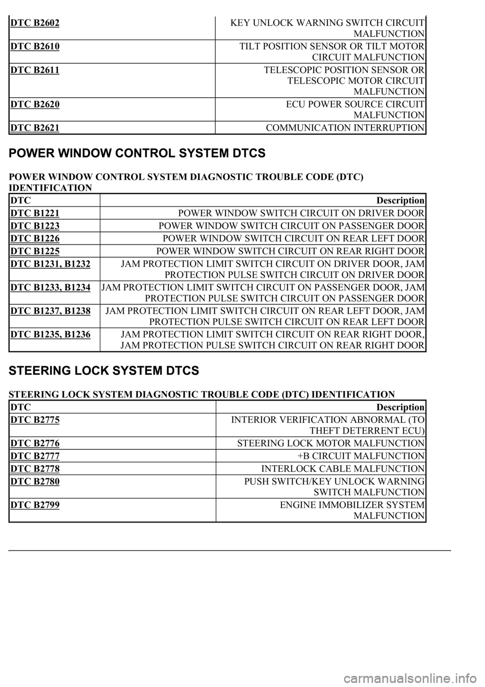
POWER WINDOW CONTROL SYSTEM DIAGNOSTIC TROUBLE CODE (DTC)
IDENTIFICATION
STEERING LOCK SYSTEM DIAGNOSTIC TROUBLE CODE (DTC) IDENTIFICATION
DTC B2602 KEY UNLOCK WARNING SWITCH CIRCUIT
MALFUNCTION
DTC B2610 TILT POSITION SENSOR OR TILT MOTOR
CIRCUIT MALFUNCTION
DTC B2611 TELESCOPIC POSITION SENSOR OR
TELESCOPIC MOTOR CIRCUIT
MALFUNCTION
DTC B2620 ECU POWER SOURCE CIRCUIT
MALFUNCTION
DTC B2621 COMMUNICATION INTERRUPTION
DTCDescription
DTC B1221 POWER WINDOW SWITCH CIRCUIT ON DRIVER DOOR
DTC B1223 POWER WINDOW SWITCH CIRCUIT ON PASSENGER DOOR
DTC B1226 POWER WINDOW SWITCH CIRCUIT ON REAR LEFT DOOR
DTC B1225 POWER WINDOW SWITCH CIRCUIT ON REAR RIGHT DOOR
DTC B1231, B1232 JAM PROTECTION LIMIT SWITCH CIRCUIT ON DRIVER DOOR, JAM
PROTECTION PULSE SWITCH CIRCUIT ON DRIVER DOOR
DTC B1233, B1234 JAM PROTECTION LIMIT SWITCH CIRCUIT ON PASSENGER DOOR, JAM
PROTECTION PULSE SWITCH CIRCUIT ON PASSENGER DOOR
DTC B1237, B1238 JAM PROTECTION LIMIT SWITCH CIRCUIT ON REAR LEFT DOOR, JAM
PROTECTION PULSE SWITCH CIRCUIT ON REAR LEFT DOOR
DTC B1235, B1236 JAM PROTECTION LIMIT SWITCH CIRCUIT ON REAR RIGHT DOOR,
JAM PROTECTION PULSE SWITCH CIRCUIT ON REAR RIGHT DOOR
DTCDescription
DTC B2775 INTERIOR VERIFICATION ABNORMAL (TO
THEFT DETERRENT ECU)
DTC B2776 STEERING LOCK MOTOR MALFUNCTION
DTC B2777 +B CIRCUIT MALFUNCTION
DTC B2778 INTERLOCK CABLE MALFUNCTION
DTC B2780 PUSH SWITCH/KEY UNLOCK WARNING
SWITCH MALFUNCTION
DTC B2799 ENGINE IMMOBILIZER SYSTEM
MALFUNCTION
Page 2426 of 4500
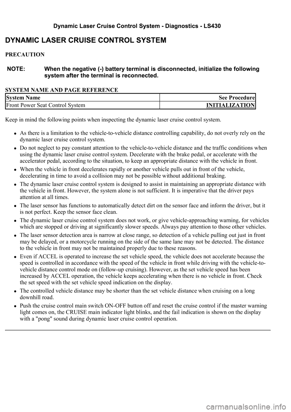
PRECAUTION
SYSTEM NAME AND PAGE REFERENCE
Keep in mind the following points when inspecting the dynamic laser cruise control system.
As there is a limitation to the vehicle-to-vehicle distance controlling capability, do not overly rely on the
dynamic laser cruise control system.
Do not neglect to pay constant attention to the vehicle-to-vehicle distance and the traffic conditions when
using the dynamic laser cruise control system. Decelerate with the brake pedal, or accelerate with the
accelerator pedal, according to the situation, to keep an appropriate distance with the vehicle in front.
When the vehicle in front decelerates rapidly or another vehicle pulls out in front of the vehicle,
decelerating in time to avoid a collision may not be possible without additional braking.
The dynamic laser cruise control system is designed to assist in maintaining an appropriate distance with
the vehicle in front. However, the system alone is not sufficient. It is imperative that the driver pays
attention at all times.
The laser sensor has functions to automatically detect dirt on the sensor face and inform the driver, but it
is not perfect. Keep the sensor face clean.
The dynamic laser cruise control system does not work, or give vehicle-approaching warning, for vehicles
which are stopped or driving at significantly slower speeds. Always pay attention to those other vehicles.
The laser sensor detection area is narrow at close range, so detection of a vehicle pulling out just in front
may be delayed, or a motorcycle running on the side of the same lane may not be detected. The distance
to the vehicle in front may not be maintained properly due to these reasons.
Even if ACCEL is operated to increase the set vehicle speed, the vehicle does not accelerate because the
speed is controlled in accordance with the speed of the vehicle in front while driving with the vehicle-to-
vehicle distance control mode on (follow-up cruising). However, as the set vehicle speed has been
increased by ACCEL operation, the vehicle keeps accelerating when there is no vehicle in front. Check
the set speed with the set vehicle speed indication on the display.
The controlled vehicle distance may be shorter than the set vehicle distance when cruising on a long
downhill road.
Push the cruise control main switch ON-OFF button off and reset the cruise control if the master warning
light comes on, the CRUISE main indicator light blinks, and the fail indication is shown on the display
with a "pong" sound during dynamic laser cruise control operation.
System NameSee Procedure
Front Power Seat Control SystemINITIALIZATION
Page 2433 of 4500
dynamic laser cruise control system.
Operation of the constant speed control mode is the same as that for the conventional type
cruise control system.
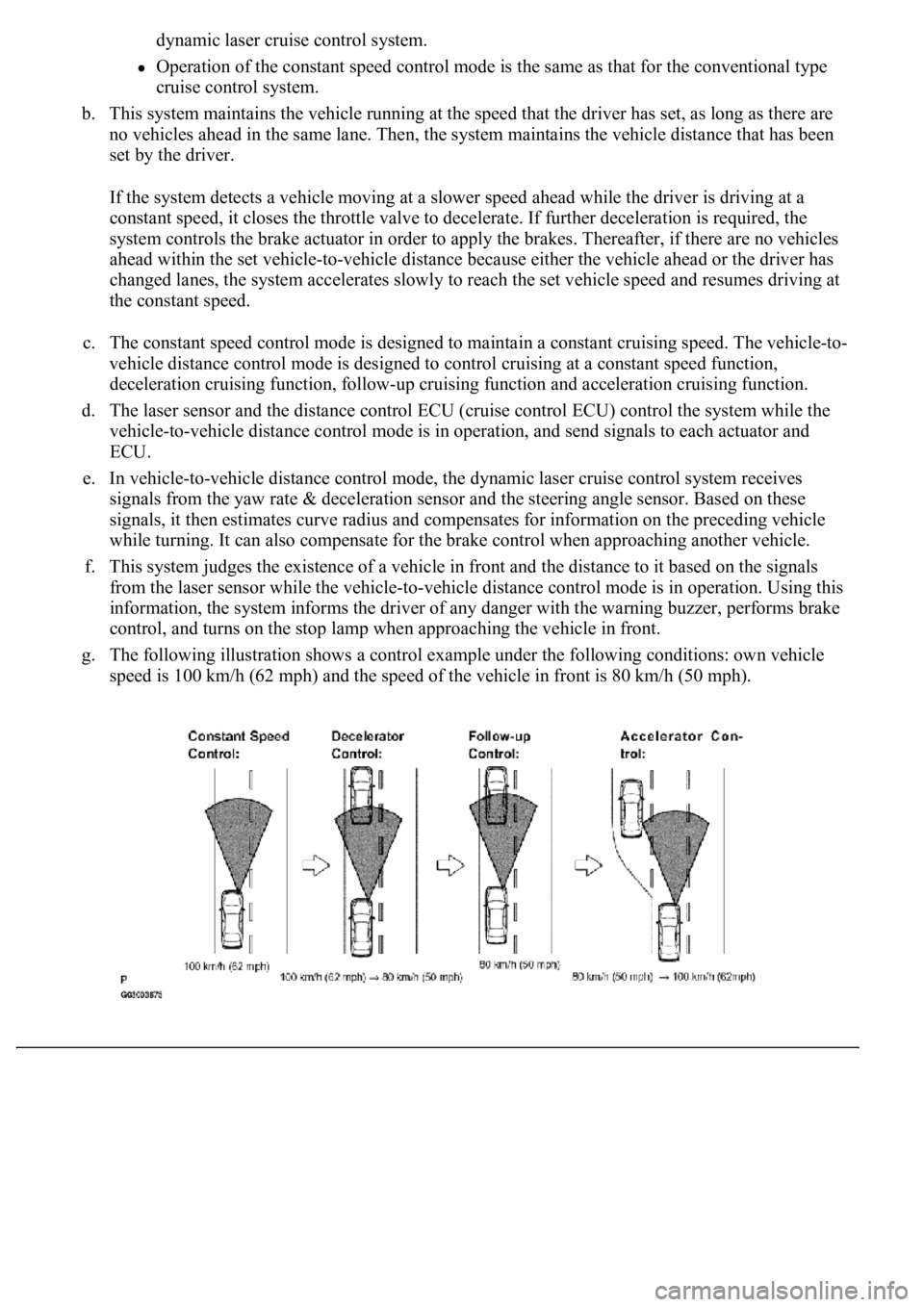
b. This system maintains the vehicle running at the speed that the driver has set, as long as there are
no vehicles ahead in the same lane. Then, the system maintains the vehicle distance that has been
set by the driver.
If the system detects a vehicle moving at a slower speed ahead while the driver is driving at a
constant speed, it closes the throttle valve to decelerate. If further deceleration is required, the
system controls the brake actuator in order to apply the brakes. Thereafter, if there are no vehicles
ahead within the set vehicle-to-vehicle distance because either the vehicle ahead or the driver has
changed lanes, the system accelerates slowly to reach the set vehicle speed and resumes driving at
the constant speed.
c. The constant speed control mode is designed to maintain a constant cruising speed. The vehicle-to-
vehicle distance control mode is designed to control cruising at a constant speed function,
deceleration cruising function, follow-up cruising function and acceleration cruising function.
d. The laser sensor and the distance control ECU (cruise control ECU) control the system while the
vehicle-to-vehicle distance control mode is in operation, and send signals to each actuator and
ECU.
e. In vehicle-to-vehicle distance control mode, the dynamic laser cruise control system receives
signals from the yaw rate & deceleration sensor and the steering angle sensor. Based on these
signals, it then estimates curve radius and compensates for information on the preceding vehicle
while turning. It can also compensate for the brake control when approaching another vehicle.
f. This system judges the existence of a vehicle in front and the distance to it based on the signals
from the laser sensor while the vehicle-to-vehicle distance control mode is in operation. Using this
information, the system informs the driver of any danger with the warning buzzer, performs brake
control, and turns on the stop lamp when approaching the vehicle in front.
g. The following illustration shows a control example under the following conditions: own vehicle
speed is 100 km/h (62 mph) and the speed of the vehicle in front is 80 km/h (50 mph).
Page 2437 of 4500
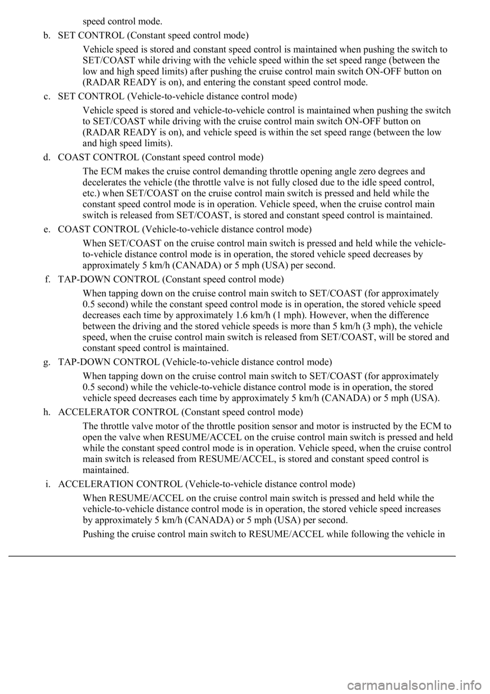
speed control mode.
b. SET CONTROL (Constant speed control mode)
Vehicle speed is stored and constant speed control is maintained when pushing the switch to
SET/COAST while driving with the vehicle speed within the set speed range (between the
low and high speed limits) after pushing the cruise control main switch ON-OFF button on
(RADAR READY is on), and entering the constant speed control mode.
c. SET CONTROL (Vehicle-to-vehicle distance control mode)
Vehicle speed is stored and vehicle-to-vehicle control is maintained when pushing the switch
to SET/COAST while driving with the cruise control main switch ON-OFF button on
(RADAR READY is on), and vehicle speed is within the set speed range (between the low
and high speed limits).
d. COAST CONTROL (Constant speed control mode)
The ECM makes the cruise control demanding throttle opening angle zero degrees and
decelerates the vehicle (the throttle valve is not fully closed due to the idle speed control,
etc.) when SET/COAST on the cruise control main switch is pressed and held while the
constant speed control mode is in operation. Vehicle speed, when the cruise control main
switch is released from SET/COAST, is stored and constant speed control is maintained.
e. COAST CONTROL (Vehicle-to-vehicle distance control mode)
When SET/COAST on the cruise control main switch is pressed and held while the vehicle-
to-vehicle distance control mode is in operation, the stored vehicle speed decreases by
approximately 5 km/h (CANADA) or 5 mph (USA) per second.
f. TAP-DOWN CONTROL (Constant speed control mode)
When tapping down on the cruise control main switch to SET/COAST (for approximately
0.5 second) while the constant speed control mode is in operation, the stored vehicle speed
decreases each time by approximately 1.6 km/h (1 mph). However, when the difference
between the driving and the stored vehicle speeds is more than 5 km/h (3 mph), the vehicle
speed, when the cruise control main switch is released from SET/COAST, will be stored and
constant speed control is maintained.
g. TAP-DOWN CONTROL (Vehicle-to-vehicle distance control mode)
When tapping down on the cruise control main switch to SET/COAST (for approximately
0.5 second) while the vehicle-to-vehicle distance control mode is in operation, the stored
vehicle speed decreases each time by approximately 5 km/h (CANADA) or 5 mph (USA).
h. ACCELERATOR CONTROL (Constant speed control mode)
The throttle valve motor of the throttle position sensor and motor is instructed by the ECM to
open the valve when RESUME/ACCEL on the cruise control main switch is pressed and held
while the constant speed control mode is in operation. Vehicle speed, when the cruise control
main switch is released from RESUME/ACCEL, is stored and constant speed control is
maintained.
i. ACCELERATION CONTROL (Vehicle-to-vehicle distance control mode)
When RESUME/ACCEL on the cruise control main switch is pressed and held while the
vehicle-to-vehicle distance control mode is in operation, the s
tored vehicle speed increases
by approximately 5 km/h (CANADA) or 5 mph (USA) per second.
Pushin
g the cruise control main switch to RESUME/ACCEL while following the vehicle in