Page 2539 of 4500

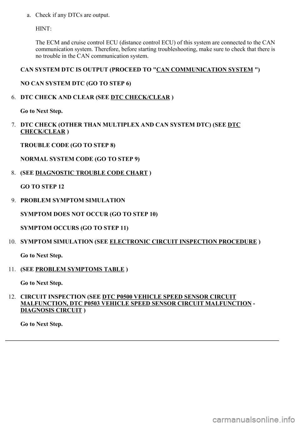
a. Check if any DTCs are output.
HINT:
The ECM and cruise control ECU (distance control ECU) of this system are connected to the CAN
communication system. Therefore, before starting troubleshooting, make sure to check that there is
no trouble in the CAN communication system.
CAN SYSTEM DTC IS OUTPUT (PROCEED TO "CAN COMMUNICATION SYSTEM
")
NO CAN SYSTEM DTC (GO TO STEP 6)
6.DTC CHECK AND CLEAR (SEE DTC CHECK/CLEAR
)
Go to Next Step.
7.DTC CHECK (OTHER THAN MULTIPLEX AND CAN SYSTEM DTC) (SEE DTC
CHECK/CLEAR )
TROUBLE CODE (GO TO STEP 8)
NORMAL SYSTEM CODE (GO TO STEP 9)
8.(SEE DIAGNOSTIC TROUBLE CODE CHART
)
GO TO STEP 12
9.PROBLEM SYMPTOM SIMULATION
SYMPTOM DOES NOT OCCUR (GO TO STEP 10)
SYMPTOM OCCURS (GO TO STEP 11)
10.SYMPTOM SIMULATION (SEE ELECTRONIC CIRCUIT INSPECTION PROCEDURE
)
Go to Next Step.
11.(SEE PROBLEM SYMPTOMS TABLE
)
Go to Next Step.
12.CIRCUIT INSPECTION (SEE DTC P0500 VEHICLE SPEED SENSOR CIRCUIT
MALFUNCTION, DTC P0503 VEHICLE SPEED SENSOR CIRCUIT MALFUNCTION -
DIAGNOSIS CIRCUIT
)
Go to Next Step.
Page 2552 of 4500
1.DISTANCE CONTROL ECU
Fig. 20: Identifying ECU Terminals
Courtesy of TOYOTA MOTOR SALES, U.S.A., INC.
ECU TERMINALS VOLTAGE AND RESISTANCE SPECIFICATION
Symbols (Terminals
No.)Wiring
ColorTerminal DescriptionConditionSpecified
Condition
+B - GND (D2-1 - D2-
12)R-B - BRBatteryAlways10 to 14V
CANH (D2 - 8)LGCAN communication
signalCAN
communication
circuit
-
CANL (D2 - 9)LCAN communication
signalCAN
communication
circuit
-
SGND - Body ground
(D2-10 - Body ground)BR - Body
groundGroundAlwaysBelow 1 ohms
GND - Body ground
(D2-12 - Body ground)BR - Body
groundGroundAlwaysBelow 1ohms
IGB - GND (D2-13 -
D2-12)L-0 - BRIgnition switch ON signalIgnition switch OFF
--> ONBelow 1 V --> 10
to 14V
LRDD - GND (D2-22 -
D2-12)P-L - BRMillimeter wave radar
sensor input signalIgnition switch ONPulse generation
(see waveform 1)
LRRD - GND (D2-23 -
D2-12)L-Y - BRMillimeter wave radar
sensor output signalIgnition switch ONPulse generation
(see waveform 2)
Page 2555 of 4500
Fig. 24: ECM Connector Terminals Voltage And Resistance Chart
Courtesy of TOYOTA MOTOR SALES, U.S.A., INC.
If the value is not within the standard range, some defects on the vehicle are suspected.
3.MILLIMETER WAVE RADAR SENSOR
Page 2556 of 4500
Fig. 25: Identifying Millimeter Wave Radar Sensor Connector Terminals
Courtesy of TOYOTA MOTOR SALES, U.S.A., INC.
MILLIMETER WAVE RADAR SENSOR CONNECTOR TERMINALS VOLTAGE AND
RESISTANCE SPECIFICATION
a. Reference: waveform 1
HINT:
Terminal: LRDD - SGND
Symbols (Terminal No.)Wiring
ColorTerminal DescriptionConditionSpecified Condition
LGND - Body ground
(M7-1 - Body ground)B-L -Body
groundGround (Distance signal)AlwaysBelow 1 ohms
SGND - Body ground
(M7-2 - Body ground)B-R - Body
groundGroundAlwaysBelow 1 ohms
LRDD - SGND (M7-3 -
M7-2)B-O - B-RMillimeter wave radar
sensor output signalIgnition
switch ONPulse generation (see
waveform 1)
LRRD - SGND (M7-4 -
M7-2)B-Y - B-RMillimeter wave radar
sensor input signalIgnition
switch ONPulse generation (see
waveform 2)
IGB - SGND (M7-5 - M7-
2)B - B-RPower sourceIgnition
switch ON10 to 14V
Page 2563 of 4500
If a malfunction occurs in the vehicle speed sensors, the stop lamp switch, or other related parts during
cruise control driving, the ECU actuates AUTO CANCEL of the cruise control and blinks the CRUISE
main indicator light. This indicator light informs the driver of the malfunction. At the same time, the
malfunction is stored as a diagnostic trouble code.
Fig. 32: Identifying Blinking Pattern Of CRUISE Main Indicator Light
Courtesy of TOYOTA MOTOR SALES, U.S.A., INC.
1.DTC CHECK
a. Connect the hand-held tester to the DLC3.
b. Turn the ignition switch to the ON position.
c. Read the DTCs by following the prompts on the tester screen.
2.DTC CLEAR
a. Connect the hand-held tester to the DLC3.
b. Turn the ignition switch to the ON position.
c. Clear the DTCs following the prompts on the tester screen.
HINT:
Refer to the han
d-held tester operators manual for further details.
Page 2567 of 4500
1.DATA LIST
HINT:
From the DATA LIST displayed on the hand-held tester, the value of components such as the switch,
sensor, and actuator can be read without parts removal. Reading the DATA LIST as the first step of
troubleshooting is one way to shorten labor time.
a. Connect the hand-held tester to the DLC3.
b. Turn the ignition switch to the ON position.
c. According to the display on the tester, read the "DATA LIST".
CC (ECM):
Page 2570 of 4500

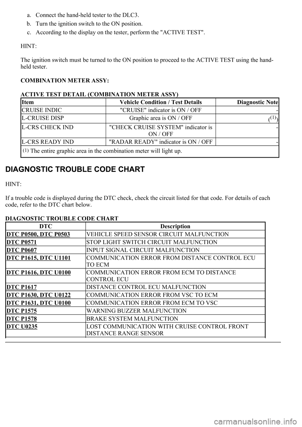
a. Connect the hand-held tester to the DLC3.
b. Turn the ignition switch to the ON position.
c. According to the display on the tester, perform the "ACTIVE TEST".
HINT:
The ignition switch must be turned to the ON position to proceed to the ACTIVE TEST using the hand-
held tester.
COMBINATION METER ASSY:
ACTIVE TEST DETAIL (COMBINATION METER ASSY)
HINT:
If a trouble code is displayed during the DTC check, check the circuit listed for that code. For details of each
code, refer to the DTC chart below.
DIAGNOSTIC TROUBLE CODE CHART
ItemVehicle Condition / Test DetailsDiagnostic Note
CRUISE INDIC"CRUISE" indicator is ON / OFF-
L-CRUISE DISPGraphic area is ON / OFF((1))
L-CRS CHECK IND"CHECK CRUISE SYSTEM" indicator is
ON / OFF-
L-CRS READY IND"RADAR READY" indicator is ON / OFF-
(1)The entire graphic area in the combination meter will light up.
DTCDescription
DTC P0500, DTC P0503VEHICLE SPEED SENSOR CIRCUIT MALFUNCTION
DTC P0571STOP LIGHT SWITCH CIRCUIT MALFUNCTION
DTC P0607INPUT SIGNAL CIRCUIT MALFUNCTION
DTC P1615, DTC U1101COMMUNICATION ERROR FROM DISTANCE CONTROL ECU
TO ECM
DTC P1616, DTC U0100COMMUNICATION ERROR FROM ECM TO DISTANCE
CONTROL ECU
DTC P1617DISTANCE CONTROL ECU MALFUNCTION
DTC P1630, DTC U0122COMMUNICATION ERROR FROM VSC TO ECM
DTC P1631, DTC U0100COMMUNICATION ERROR FROM ECM TO VSC
DTC P1575WARNING BUZZER MALFUNCTION
DTC P1578BRAKE SYSTEM MALFUNCTION
DTC U0235LOST COMMUNICATION WITH CRUISE CONTROL FRONT
DISTANCE RANGE SENSOR
Page 2571 of 4500
DTC U1102LOST COMMUNICATION WITH RADAR SENSOR
DTC P1572IMPROPER AIMING OF RADAR SENSOR BEAM AXIS
DTC U0126LOST COMMUNICATION WITH STEERING ANGLE SENSOR
MODULE
DTC U0123LOST COMMUNICATION WITH YAW RATE SENSOR MODULE